Language selection

Search

Patent 3088257 Summary

Third-party information liability

Some of the information on this Web page has been provided by external sources. The Government of Canada is not responsible for the accuracy, reliability or currency of the information supplied by external sources. Users wishing to rely upon this information should consult directly with the source of the information. Content provided by external sources is not subject to official languages, privacy and accessibility requirements.

Claims and Abstract availability

Any discrepancies in the text and image of the Claims and Abstract are due to differing posting times. Text of the Claims and Abstract are posted:

  • At the time the application is open to public inspection;
  • At the time of issue of the patent (grant).
(12) Patent Application: (11) CA 3088257
(54) English Title: LEAK DETECTION IN A HYDROGEN FUELLED VEHICLE
(54) French Title: DETECTION DE FUITE DANS UN VEHICULE ALIMENTE A L'HYDROGENE
Status: Examination Requested
Bibliographic Data
(51) International Patent Classification (IPC):
  • G01M 3/26 (2006.01)
  • H01M 8/04664 (2016.01)
  • F02D 19/02 (2006.01)
  • F02D 19/06 (2006.01)
  • F02D 19/08 (2006.01)
  • F02D 41/00 (2006.01)
  • F02M 21/02 (2006.01)
(72) Inventors :
  • TURNER, PAUL (United Kingdom)
  • JASPER, TREVOR (United Kingdom)
(73) Owners :
  • ULEMCO LIMITED (United Kingdom)
(71) Applicants :
  • ULEMCO LIMITED (United Kingdom)
(74) Agent: ANDREWS ROBICHAUD
(74) Associate agent:
(45) Issued:
(86) PCT Filing Date: 2019-01-18
(87) Open to Public Inspection: 2019-08-01
Examination requested: 2023-12-20
Availability of licence: N/A
(25) Language of filing: English

Patent Cooperation Treaty (PCT): Yes
(86) PCT Filing Number: PCT/GB2019/050146
(87) International Publication Number: WO2019/145686
(85) National Entry: 2020-07-10

(30) Application Priority Data:
Application No. Country/Territory Date
1801094.2 United Kingdom 2018-01-23

Abstracts

English Abstract

The invention concerns a method of detecting hydrogen leakage from a power plant installation using hydrogen as fuel. A rate of supply of hydrogen to the power plant ("the supply rate") is determined. A rate of change of mass of hydrogen in the tank arrangement ("the rate of mass change") is determined. The supply rate is compared with the rate of mass change to determine whether leakage is taking place.


French Abstract

L'invention concerne un procédé de détection de fuite d'hydrogène à partir d'une installation de centrale électrique utilisant de l'hydrogène comme combustible. Un taux d'alimentation en hydrogène de la centrale électrique ("le taux d'alimentation") est déterminé. Un taux de changement de masse d'hydrogène dans l'agencement de réservoir ("le taux de changement de masse") est déterminé. Le taux d'alimentation est comparé au taux de changement de masse pour déterminer si une fuite a lieu.

Claims

Note: Claims are shown in the official language in which they were submitted.

CA 03088257 2020-07-10
WO 2019/145686
PCT/GB2019/050146
CLAIMS
1. A method of detecting hydrogen leakage from a power plant which is wholly
or partially fuelled by
hydrogen supplied to the power plant from a tank arrangement, the method
comprising
determining a rate of supply of hydrogen to the power plant ("the supply
rate");
determining a rate of change of mass of hydrogen in the tank arrangement ("the
rate of mass
change"); and
comparing the supply rate with the rate of mass change to determine whether
leakage is taking place.
2. A method as claimed in claim 1 in which determining the rate of mass change
comprises sensing
temperature and pressure in a tank of the tank arrangement.
3. A method as claimed in claim 2 in which the tank arrangement further
comprises at least one
hydrogen supply line leading from the tank to the power plant, and in which
the method further
comprises sensing temperature and pressure in the supply line, the rate of
mass change being based
on the sum of a rate of mass change in the tank and a rate of mass change in
the supply line.
4. A method as claimed in claim 3 in which the hydrogen supply line comprises
a pressure regulator
and the method further comprises sensing temperature and pressure at two
points in the supply line,
one upstream of the pressure regulator and the other downstream of the
pressure regulator.
5. A method as claimed in any preceding claim in which the power plant is an
internal combustion
engine having at least one fuel injector and the method comprises determining
the rate of supply of
hydrogen to the engine based on engine operating parameters including the
state of the fuel injector.
6. A method as claimed in any preceding claim in which the power plant is
arranged to be fuelled by
hydrogen and by a second fuel, the method comprising:
making a first determination whether leakage is taking place by comparison of
the supply rate
with the rate of mass change,
in the event that the first determination is indicative of leakage, suspending
supply of
hydrogen to the power plant and fuelling the power plant with the second fuel
during the
suspension of hydrogen supply, and
making a second determination whether leakage is taking place by making at
least two
temporally separated measurements of mass of hydrogen in the tank arrangement.
7. A method as claimed in claim 6 in which action responsive to leakage is
initiated if the second
determination is indicative of leakage.
5

CA 03088257 2020-07-10
WO 2019/145686
PCT/GB2019/050146
8. A method as claimed in any preceding claim implemented on board a vehicle
powered by the power
plant.
9. A power plant installation configured to operate according to the method of
any preceding claim.
10. A computer program which, when run on an engine controller, causes it to
operate according to
the method of any of claims 1 to 7.
11. A system for detection of hydrogen leakage from an installation comprising
a power plant fuelled
at least partly with hydrogen and a tank arrangement for storing hydrogen and
supplying it to the
power plant, the system comprising a sensor arrangement for sensing
temperature and pressure in a
tank of the tank arrangement and a digital processor for:
determining a rate of supply of hydrogen to the power plant ("the supply
rate");
determining a rate of change of mass of hydrogen in the tank arrangement ("the
rate of mass
change"); and
comparing the supply rate with the rate of mass change to determine whether
leakage is taking place.
12. A system for detection of hydrogen leakage as claimed in claim 11 which
comprises a further
.. sensor arrangement for sensing temperature and pressure in a supply line
leading from the tank to
the power plant.
6

Description

Note: Descriptions are shown in the official language in which they were submitted.


CA 03088257 2020-07-10
WO 2019/145686
PCT/GB2019/050146
LEAK DETECTION IN A HYDROGEN FUELLED VEHICLE
The invention is concerned with detection of leakage of hydrogen in a vehicle
which is at least partly
hydrogen fuelled.
There are powerful economic and societal incentives to reduce the consumption
of hydrocarbon
based fuels in the internal combustion engines of vehicles. Release of carbon
by their combustion is
thought to be a major contributor to global warming. The Earth's resources of
crude oil are finite, and
its extraction harms the environment in various ways.
Hydrogen has long been suggested as a substitute for hydrocarbon based fuels
and the modern focus
on reduction of carbon release into the atmosphere has only increased its
attraction in this respect.
But for a range of technical and social reasons widespread adoption of
hydrogen fuelling of vehicles
has not taken place at the time of writing.
One concern about the use of hydrogen to fuel vehicles is the apparent hazard
associated with any
accidental leakage. Hydrogen is often stored on-board such vehicles at high
pressure. Hydrogen is of
course potentially explosive at sufficiently high concentrations. There is a
widespread perception that
escaping hydrogen poses an explosion risk.
The real severity of this risk is open to question. Because of its very low
density, hydrogen released
into the atmosphere rises and so disperses very rapidly. It is consequently
unlikely that a concentration
sufficient to cause an explosion could be created by the fuelling system of a
vehicle. Be that as it may,
there are legal requirements for detection of hydrogen leakage from such
systems.
.. This presents a technical challenge. Leakage of denser gases such as the
natural gas used in mains
supply systems can be detected by detecting the gas itself in the vicinity of
a leak. But this approach
is less effective in relation to hydrogen because of the rapid dispersion
already referred to. A vehicle
provides various possible points of leakage and providing each with a local
detector is not considered
feasible.
So a means is needed for detection of leakage of hydrogen in relation to a
vehicle which is at least
partially hydrogen fuelled.
The vehicle in question may in principle be driven by a hydrogen burning
internal combustion engine,
or by a hydrogen fuel cell powering an electric motor, or by an internal
combustion engine fuelled on
a combination of hydrogen with another fuel. The term "power plant" is used
herein to refer to any
.. of these devices, and to any engine or other machine or arrangement which
receives hydrogen as fuel
and which is able to provide mechanical power.
1

CA 03088257 2020-07-10
WO 2019/145686
PCT/GB2019/050146
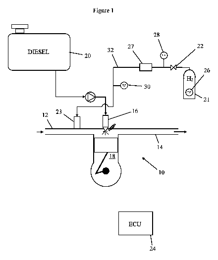
A specific embodiment of the present invention will now be described, by way
of example only, with
reference to the accompanying drawing, which is a schematic representation of
parts of an engine
and its fuelling system operable in accordance with the invention.
The embodiment of the invention described herein is implemented in relation to
a vehicle engine 10
which is an internal combustion engine fuelled by a mixture of hydrogen and a
hydrocarbon fuel,
specifically diesel.
The engine 10 has an air intake manifold 12, an exhaust 14, and a set of fuel
injectors 16 and 23
associated with respective combustion chambers 18, only one of which is seen
in the drawings. Diesel
fuel is drawn from a tank 20 and supplied to the injectors 16. Hydrogen is
stored in pressure tank 21
.. in liquid or gaseous form and at high pressure (which purely by way of
example may be in the range
of 35 to 70 MPa), and is supplied to the engine fuel intake manifold via a
tank valve 22, a high pressure
regulator unit 27 and injectors 23.
Operation of the engine is under the control of an electronic processing
system represented in the
drawing as an ECU (electronic control unit) 24. Control connections from the
ECU 24 are not
represented in the drawings for the sake of simplicity. Note that while a
single ECU 24 is depicted and
described, the processing tasks involved in engine management and in leak
detection may in practice
be carried out by separate devices.
Sensors 26 are provided for monitoring the quantity of fuel in the hydrogen
fuel tank 21. More
specifically, what the sensors are used to monitor in the present embodiment
is mass of hydrogen in
the tank. The sensors 26 detect temperature and pressure of the hydrogen in
the tank. The volume of
the tank is known, as is the relationship between density, temperature and
pressure of the stored
hydrogen. This relationship is close to the ideal gas law, according to which
the product of pressure
and volume is proportional to the product of mass and temperature, although
the true relationship is
slightly more complex, deviating slightly from a truly linear relationship.
The behaviour of compressed
gases is very well known to the skilled person and this aspect requires no
further explanation in the
present context.
Based on the measured temperature and pressure, and the known tank volume, the
ECU 24
determines the mass of hydrogen in the tank 21. One could equivalently say
that the ECU 24
determines the number of moles of H2.
Further sensor stations 28, 30 measure temperature and pressure in lines 32
leading from the tank 21
to the engine 10 at locations upstream and downstream of the pressure
regulator unit 24,
respectively. Their outputs are used to establish the mass of hydrogen in the
lines 32.
2

CA 03088257 2020-07-10
WO 2019/145686
PCT/GB2019/050146
The leak monitoring system is used whilst the engine is not running to perform
static leak testing. This
may for example be carried out after the engine has been switched off ("key
off") and/or when the
engine is started ("key on"). Values from a key off test and the next key on
test may be compared to
test for leakage taking place during inactive periods. An increase in hydrogen
mass from key off to key
on may of course be attributed to fuelling of the vehicle, and may be ignored.
A static leak test comprises taking at least two temporally separated
measurements of temperature
and pressure, and calculating from them the mass of hydrogen in the lines (if
the tank valve 22 is
closed) or in the tank and the lines 32 (if the tank is open). If the mass
calculated from the second
measurement is lower than that calculated from the first by more than a
certain margin, this is
interpreted as being indicative of leakage of hydrogen and suitable action is
triggered in response,
such as provision of a visual or audible warning for a driver.
The static leak may involve more than two tests. It may include multiple
measurements to reduce the
effect of noise. It may comprise numerical differentiation of the calculated
mass such that a leak is
inferred if the mass reduces at anything above a threshold rate.
The leak monitoring system is also used to carry out dynamic leak testing
whilst the engine is running.
For this purpose an estimate is made of the mass per unit time of hydrogen
supplied to the engine 10.
This estimate can be made from engine operating parameters known to the ECU
24, which may
comprise the control signals applied to the injectors 16 and the regulator
unit 24. The rate of hydrogen
consumption estimated in this manner is compared to the rate of change of the
mass of hydrogen in
the tank 20 and the lines 32, calculated from the outputs of the sensor
stations 26, 28, 30. If the latter
is found to be greater than the former, this is suggestive of a leak.
In principle, the system could, in response to this condition, determine that
leakage is taking place and
provide a suitable response, e.g. by shutting down the engine and other
systems and giving the driver
a warning signal. But a problem arises due to limited sensor resolution.
Pressure in the hydrogen tank
21 is high ¨ it may for example by 70mPa when full, in a typical system. A
small error in the sensed
tank pressure or temperature can create an error in the tank mass which is
large in proportion to the
rate of consumption of hydrogen by the engine, potentially causing the dynamic
leak process to yield
a "false positive" ¨ an indication of a leak where none is actually taking
place.
The problem is obviated in the present embodiment in the following manner.
In response to a positive outcome of a dynamic leak detection test, the system
does not immediately
shut down the engine. Instead, hydrogen supply to the engine 10 is suspended.
The engine is fuelled
solely with diesel while a static leak test is carried out in the manner
described above. If the static leak
3

CA 03088257 2020-07-10
WO 2019/145686 PCT/GB2019/050146
test is negative then it is determined that there is no leakage and hydrogen
fuelling re-commences. If
the static leak test is positive then the system responds accordingly, e.g.
with a driver warning and/or
automatic engine shutdown.
4

Representative Drawing
A single figure which represents the drawing illustrating the invention.
Administrative Status

For a clearer understanding of the status of the application/patent presented on this page, the site Disclaimer , as well as the definitions for Patent , Administrative Status , Maintenance Fee  and Payment History  should be consulted.

Administrative Status

Title Date
Forecasted Issue Date Unavailable
(86) PCT Filing Date 2019-01-18
(87) PCT Publication Date 2019-08-01
(85) National Entry 2020-07-10
Examination Requested 2023-12-20

Abandonment History

There is no abandonment history.

Maintenance Fee

Last Payment of $210.51 was received on 2023-12-15


 Upcoming maintenance fee amounts

Description Date Amount
Next Payment if small entity fee 2025-01-20 $100.00
Next Payment if standard fee 2025-01-20 $277.00

Note : If the full payment has not been received on or before the date indicated, a further fee may be required which may be one of the following

  • the reinstatement fee;
  • the late payment fee; or
  • additional fee to reverse deemed expiry.

Patent fees are adjusted on the 1st of January every year. The amounts above are the current amounts if received by December 31 of the current year.
Please refer to the CIPO Patent Fees web page to see all current fee amounts.

Payment History

Fee Type Anniversary Year Due Date Amount Paid Paid Date
Application Fee 2020-07-10 $400.00 2020-07-10
Maintenance Fee - Application - New Act 2 2021-01-18 $100.00 2021-01-14
Maintenance Fee - Application - New Act 3 2022-01-18 $100.00 2022-01-11
Maintenance Fee - Application - New Act 4 2023-01-18 $100.00 2023-01-11
Maintenance Fee - Application - New Act 5 2024-01-18 $210.51 2023-12-15
Request for Examination 2024-01-18 $816.00 2023-12-20
Owners on Record

Note: Records showing the ownership history in alphabetical order.

Current Owners on Record
ULEMCO LIMITED
Past Owners on Record
None
Past Owners that do not appear in the "Owners on Record" listing will appear in other documentation within the application.
Documents

To view selected files, please enter reCAPTCHA code :


To view images, click a link in the Document Description column. To download the documents, select one or more checkboxes in the first column and then click the "Download Selected in PDF format (Zip Archive)" or the "Download Selected as Single PDF" button.

List of published and non-published patent-specific documents on the CPD .

If you have any difficulty accessing content, you can call the Client Service Centre at 1-866-997-1936 or send them an e-mail at CIPO Client Service Centre.


Document
Description 
Date
(yyyy-mm-dd) 
Number of pages   Size of Image (KB) 
Abstract 2020-07-10 1 57
Claims 2020-07-10 2 68
Drawings 2020-07-10 1 7
Description 2020-07-10 4 157
Representative Drawing 2020-07-10 1 5
Patent Cooperation Treaty (PCT) 2020-07-10 11 399
International Search Report 2020-07-10 3 81
National Entry Request 2020-07-10 7 220
Cover Page 2020-09-10 1 32
Claims 2023-12-21 5 219
Claims 2023-12-20 5 219
PPH Request / Request for Examination / Amendment 2023-12-20 15 774
PPH OEE 2023-12-20 6 534
Examiner Requisition 2024-01-09 4 197
Amendment 2024-05-09 25 912
Change to the Method of Correspondence 2024-05-09 8 351
Description 2024-05-09 8 399
Claims 2024-05-09 5 260