Note: Descriptions are shown in the official language in which they were submitted.
CA 03089247 2020-07-21
WO 2019/145602 PCT/F12019/050043
1
Arrangement and method for installing casing
Background
The invention relates to an arrangement for installing a casing.
The invention further relates to a method for installing a casing.
An effective way to install a casing or pole to hard ground when the
casing is driven partly into a rock, for example, is percussive drilling. In
such a
case, a casing has inside it boring pipes, and at an end of the boring pipe, a
percussion hammer, such as a down-the-hole-hammer type, or DTH hammer.
A boring pipe has a centre opening through which compressed air required by
the DTH hammer is fed to it. The boring pipe, DTH hammer, pilot crown and
reamer connected to the latter are simultaneously rotated by a rotation mecha-
nism at the top end of the boring pipe.
The boring of the hole takes place by means of the percussion func-
tion generated by the hammer, and the rotation of the boring pipe. The purpose
of the reamer is to broaden the hole made by the pilot crown so big that the
casing fits into the drilled hole. The casing may additionally have a so-
called
casing shoe by means of which the pilot crown pulls the casing with it into
the
drilled hole. The removal of released material takes place by means of exhaust
air of the DTH hammer. Here, the exhaust air of the DTH hammer is led, by
means of bores in the pilot crown, to the bottom of the hole being drilled,
from
where the attempt is made to lead the air flow that takes released material
with
it inside the casing and from the casing further to the surface of the ground.
The problem here is that typically part of the air flow will inevitably
escape to the ground. Excessive escaping of air may significantly reduce the
bearing strength of the surrounding ground and consequently cause danger to
structures in the surroundings, such as the foundations of buildings.
It is partly possible to manage the escaping of air to the ground by
the design of the pilot crown. In particular, a crown in which the blowing of
flush-
ing air to the bottom of a hole is turned parallel to the bottom of the hole
before
it discharges from the crown reduces the escaping of air into the ground.
Another, far more effective way is to use a separate flushing circuit
where the flushing of the borehole does not takes place by means of exhaust
air, but with water or another, similar flushing medium. This allows the use
of the
so-called RC drilling system (Reverse Circulation). The RC drilling system was
originally developed for research drilling where the loose material that
drilling
CA 03089247 2020-07-21
WO 2019/145602 PCT/F12019/050043
2
creates is flushed up from the bottom of a hole along a centre opening of a
two-
layer drill pipe whereby it may be stored for later analysis.
The RC system consists of RC boring pipes and an RC hammer. The
RC boring pipe typically has an outer pipe and an inner pipe, where an inner
opening of the inner pipe and the space between the outer pipe and inner pipe
form two separate flow channels. The operation of the actual RC hammer is
identical to that of a normal DTH hammer. An RC hammer has a pipe passing
through the hammer, along which exhaust air of the hammer flows through the
hammer, carrying with it the released material. The percussion piston of the
hammer has a relatively large centre opening for the pipe so that the pipe in
question and the air flow channel, essential for the operations of the DTH ham-
mer, fit through the percussion piston.
The RC boring system may be applied to ground boring when it is
desired to prevent air from escaping to the ground.
In this case, an RC boring pipe is used to feed the operating com-
pressed air needed by the RC hammer, and well as the flushing medium, such
as water, to the RC hammer. The flushing medium is typically supplied through
the inner opening of the inner pipe, and the compressed air is supplied
through
the space between the pipes. The exhaust air of the RC hammer is fed through
the drill crown inside the casing, from where it exits to the ground surface.
The
flushing medium is fed through the pipe passing through the RC hammer further
through the drill crown to the bottom of the hole from where it flushes the re-
leased material with it. After this, the flushing medium and released material
are
transferred to the ground surface along the gap between the casing and hole.
The method making use of the RC boring system is most suited to
boring sites where the escaping of air to the ground is not permitted at all.
The
problem, however, exists that the pipe passing through the RC hammer requires
a percussion hammer with a relatively large centre opening. This substantially
reduces the mass of the piston and the pneumatic working surfaces on which
the percussion piston is moved back and forth. In other words, the boring
power
generated by an RC hammer is substantially lower than that of a conventional
DTH hammer.
Brief disclosure
The arrangement and method of the invention are characterized by
what is disclosed in the independent claims. The other embodiments of the in-
vention are characterised by what is disclosed in the rest of the claims.
CA 03089247 2020-07-21
WO 2019/145602 PCT/F12019/050043
3
Inventive embodiments are also disclosed in the specification and
drawings of this application. The inventive content of the application may
also
be defined differently than in the claims presented below. The inventive
content
may also consist of several separate inventions, particularly if the invention
is
examined in the light of disclosed or implicit subtasks or from the point of
view
of gained advantages or groups of advantages. In such a case, some of the
definitions in the claims below may be irrelevant to the separate inventive
ideas.
The features of the different embodiments of the invention may be applied to
other embodiments within the scope of the basic inventive idea.
In accordance with an idea, the arrangement for installing a casing in
a borehole comprises a casing and boring pipe which is adapted within the cas-
ing, the boring pipe comprising flow channels for compressed air and a
flushing
medium, the flushing medium flow channel being arranged to lead flushing me-
dium to the bottom of the borehole, as well as a percussion hammer which com-
.. prises a compressed air operated percussion piston adapted in a cylinder of
the
percussion hammer, and hole drilling means for drilling a hole for the casing,
the
flushing medium flow channel being adapted to bypass the percussion piston.
An arrangement according to an embodiment for installing a casing
in a borehole comprises a casing and boring pipe adapted within the casing,
the
boring pipe comprising a flow channel for compressed air. The arrangement fur-
ther comprises a flow channel for a flushing medium, which is adapted within
the casing and arranged to lead the flushing medium to the bottom of the bore
hole, as well as a percussion hammer which comprises a compressed air oper-
ated percussion piston adapted in a cylinder of the percussion hammer, and
.. hole drilling means for drilling a hole for the casing, the flushing medium
flow
channel being adapted to bypass the percussion piston, or in which arrangement
the drilling means additionally comprise splines transmitting a rotating
motion
and adapted to conduct the compressed air that used the percussion piston
through the splines, and in which arrangement the flushing medium flow channel
is adapted to pass through the percussion piston.
An arrangement according to an embodiment for installing a casing
in a borehole comprises a casing and boring pipe which is adapted within the
casing, the boring pipe comprising a flow channel for compressed air and a
flow
channel for a flushing medium, which is adapted within the casing and arranged
.. to lead the flushing medium to the bottom of the bore hole, as well as a
percus-
sion hammer which comprises a compressed air operated percussion piston
CA 03089247 2020-07-21
WO 2019/145602 PCT/F12019/050043
4
adapted in a cylinder of the percussion hammer, and hole drilling means for
drilling a hole for the casing, the flushing medium flow channel being adapted
to
bypass the percussion piston, or in which arrangement the drilling means addi-
tionally comprise splines transmitting a rotating motion and adapted to
conduct
the compressed air that used the percussion piston through the splines, and in
which arrangement the flushing medium flow channel is adapted to pass through
the percussion piston.
According to a second idea, the method for installing a casing utilises
an arrangement that comprises a casing and boring pipe as well as a percussion
hammer and hole drilling means, in which method the boring pipe is rotated in-
side the casing, the percussion hammer is used by compressed air, and the
bottom of the bore hole is flushed by a flushing medium which is led past the
percussion piston of the percussion hammer from the boring pipe to the hole
drilling means and further to the bottom of the borehole.
According to an idea, the method for installing a casing utilises an
arrangement that comprises a casing and boring pipe, a percussion hammer
and means for boring a hole, in which method the boring pipe is rotated inside
the casing, the percussion hammer is used by compressed air, and the bottom
of the bore hole is flushed by a flushing medium which is led past the
percussion
piston of the percussion hammer to the hole drilling means and further to the
bottom of the borehole, or the bottom of the borehole is flushed by the
flushing
medium that is led through the percussion piston to the hole drilling means
and
further to the bottom of the hole, and in which arrangement the drilling means
additionally comprise splines transmitting a rotating motion, by means of
which
the compressed air that used the percussion piston is conducted through the
splines.
In the following, some embodiments of the invention are presented in
a random order.
According to an embodiment, on the outside of the cylinder of the
percussion hammer there is adapted a shell which together with said cylinder
wall forms a part of the flushing medium flow channel, the part bypassing the
percussion piston.
According to an embodiment, the part of the flushing medium flow
channel, which bypasses the percussion piston, extends circularly around the
cylinder of the percussion hammer.
CA 03089247 2020-07-21
WO 2019/145602 PCT/F12019/050043
According to an embodiment, the shell adapted on the outside of the
cylinder forms part of the outer surface of the percussion hammer.
According to an embodiment, on the outside of the cylinder of the
percussion hammer there are adapted one or more pipes which form part of the
5 flushing medium flow channel, bypassing the percussion piston.
According to an embodiment, the part of the flushing medium flow
channel, which bypasses the percussion piston is by its top end connected to
an adaptor of the boring pipe, having an adapter flow channel which is
arranged
to move the flushing medium flow channel further from the longitudinal centre
axis of the arrangement.
According to an embodiment, the arrangement further comprises at
least one collar which is connected to the casing or to a casing shoe fixed to
the
casing, where the part of the flushing medium flow channel, bypassing the per-
cussion piston, is by its bottom end connected to at least one collar.
According to an embodiment, at least one collar in the arrangement
additionally comprises at least one locking member for locking the at least
one
collar to the casing or casing shoe.
According to an embodiment, the at least one locking member is
adapted to lock the at least one collar to the casing or casing shoe by means
of
a pressurised flushing medium.
According to an embodiment, the at least one locking part comprises
a pressure line which is adapted to lock the at least one collar to the casing
or
casing shoe.
According to an embodiment, the percussion hammer comprises a
bottom member which has at least one flushing medium flow channel of the
bottom member, which is adapted in flow connection to the part of the flushing
medium flow channel, bypassing the percussion piston, and in which the hole
drilling means comprise at least one flushing medium flow channel of the
drilling
means, which is adapted in flow connection to the flushing medium flow channel
of the bottom member and to lead the flushing medium to the bottom of the
borehole.
According to an embodiment, the flow channel of the bottom member
comprises a circular flow groove which is adapted on the inner surface of the
bottom member and which circulates in the plane of said inner surface, which
is
at least substantially perpendicular to the longitudinal centre axis of the
arrange-
ment.
CA 03089247 2020-07-21
WO 2019/145602 PCT/F12019/050043
6
According to an embodiment, the width of the circular flow groove,
that is, the dimension in the direction of the longitudinal centre axis of the
ar-
rangement, is dimensioned wide enough so that the flushing medium flow chan-
nel stays open for the entire duration of the boring work regardless of the
move-
ment of the drilling means.
According to an embodiment, there are seals adapted on both sides
of the circular flow groove.
According to an embodiment, the hole drilling means comprise at
least one flushing medium flow channel of the drilling means, which is adapted
to lead the flushing medium from the flushing medium flow channel to the
bottom
of the borehole, and in which arrangement the flushing medium flow channel is
adapted to pass through the percussion piston.
According to an embodiment, the compressed air that used the per-
cussion piston is removed by an exhaust air channel that comprises a centre
opening in the hole drilling means, which is in flow connection to the
cylinder of
the percussion hammer, and at least one air channel passing radially through
the bottom member of the percussion hammer, the air channel being in flow
connection to the space between the percussion hammer and casing.
According to an embodiment, the drilling means additionally comprise
splines transmitting a rotating movement and adapted to conduct the com-
pressed air that used the percussion piston through the splines.
According to an embodiment, the compressed air that used the per-
cussion piston is removed by an exhaust air channel which comprises at least
one side exhaust air channel led past the hole drilling means, which is in
flow
connection to the cylinder of the percussion hammer, and an air flow channel
which is in flow connection to said at least one exhaust air channel, and at
least
one air channel passing radially through the bottom member of the percussion
hammer, the air channel being in flow connection to the space between the per-
cussion hammer and casing.
According to an embodiment, the side exhaust air channel is formed
among the splines.
According to an embodiment, the circular flow groove which is
adapted on the inner surface of the bottom member, facing the drilling means,
and circulates in the plane of a part of said inner surface, which is at least
sub-
stantially perpendicular to the longitudinal centre axis of the arrangement.
CA 03089247 2020-07-21
WO 2019/145602 PCT/F12019/050043
7
According to an embodiment, the percussion hammer is a DTH ham-
mer.
Brief description of the drawings
The invention is described in more detail in the accompanying draw-
ings, in which
Figure 1 is a schematic sectional side view of an arrangement for
installing a casing,
Figure 2a is a schematic sectional side view of a second arrangement
for installing a casing,
Figure 2b shows a cross section A-A of the arrangement of Figure
2a,
Figure 3a is a schematic sectional side view of a third arrangement
for installing a casing,
Figure 3b is a schematic sectional side view of a detail of the arrange-
ment of Figure 3a,
Figure 4a is a schematic sectional side view of an arrangement for
installing a casing,
Figure 4b is a schematic sectional side view of a detail of the arrange-
ment of Figure 4a,
Figures 5a to 5c are sectional side views of alternative details of a
collar of the arrangement of Figures 4a and 4b,
Figure 6 is a schematic sectional side view of a detail of an arrange-
ment,
Figure 7a is a schematic sectional side view of an arrangement for
installing a casing,
Figure 7b is a schematic sectional side view of a detail of the arrange-
ment of Figure 7a, and
Figure 8 is a side view of a detail of collar of an arrangement.
For the sake of clarity, the figures show the invention in a simplified
manner. Similar parts are indicated in the figures by the same reference num-
bers.
Detailed description
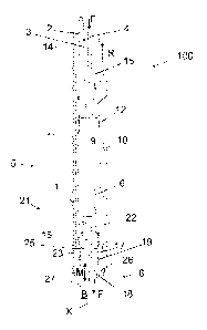
Figure 1 is a schematic sectional side view of an arrangement for
installing a casing.
CA 03089247 2020-07-21
WO 2019/145602 PCT/F12019/050043
8
The arrangement 100 comprises a casing 1, which is a tubular piece
installed in the ground, typically permanently. At the installation stage of
the cas-
ing 1, boring pipe 2 has been adapted inside it to be rotated inside the
casing.
The arrangement 100 further comprises a percussion hammer 5 which is oper-
ated by compressed air. For this purpose, the arrangement 100 features a flow
channel for compressed air 3. The bottom X of the borehole is flushed by a
flushing medium which is fed to the bottom B of the borehole through the flow
channel 4.
The flushing medium may be water, a mixture containing water, such
as boring sludge, or another suitable substance in a flowing form.
The percussion hammer 5 shown in Figure 5 is a compressed air op-
erated DTH hammer (down-the-hole-hammer). Obviously, the percussion ham-
mer 5 may, as concerns it basic idea, be a hammer other than a DTH hammer.
Note, however, that the drawings only show the hammer parts that
are essential from the viewpoint of the invention. The figures show an embodi-
ment of the DTH hammer, which does not utilise a foot valve installed to the
top
end of a pilot crown. The arrangement according to the invention is naturally
also suitable for embodiments provided with a foot valve.
The percussion hammer 5 comprise a compressed air operated per-
cussion hammer 6 which is adapted to the cylinder 9 of the percussion hammer
movably back and forth.
The arrangement 100 further comprises hole drilling means 8 for bor-
ing a hole into the ground for the casing 1. In the embodiment shown in the
figure, the drilling means 8 comprise a pilot crown 26 and reamer 27. The
drilling
means 8 may be formed in another manner: in an embodiment, the drilling
means 8 comprise a so-called wing reamer, in another words, a drill crown with
wings that open.
In the arrangement, the flushing medium flow channel 4 is adapted to
bypass the percussion piston 6 of the percussion hammer 5. The advantage of
this arrangement is that the flushing of the bottom B of the borehole may be
effectively implemented with the use of a separate flushing circuit, while the
drill-
ing power of the percussion piston is high due to the large mass and large
pneu-
matic working area of the percussion piston. According to an idea, it may be
noted that the advantages of a DTH hammer and RC hammer have been com-
bined.
CA 03089247 2020-07-21
WO 2019/145602 PCT/F12019/050043
9
In the embodiment shown in Figure 1, the flushing medium flow chan-
nel 4 comprises a part 12 which bypasses the percussion piston 6 and which
extends in a circular manner around the cylinder 9 of the percussion hammer.
Said part 12 of the flow channel is formed by adapting a tubular shell 10
around
the cylinder 9. The shell may be formed of steel or similar. In accordance
with
Figure 1, the shell 10 adapted outside the cylinder 9 may form part of the
outer
surface of the percussion hammer 5, but this is not compulsory, however.
The part 12 bypassing the flushing medium flow channel of the per-
cussion piston connects at its top end to an adaptor 14 of the boring pipe,
which
connects the boring pipe 2 to the percussion hammer 5. The boring pipe adaptor
14 has an adaptor flow channel 15 which is arranged to shift the flushing
medium
flow channel 4 further from the longitudinal centre axis X of the arrangement,
whereby the part 12 of the flow channel may be advantageously connected, in
the flow technical sense, to the flushing medium channel in the boring pipe.
The percussion hammer 5 comprises a bottom member 16 which has
at least one flushing medium flow channel 17 of the bottom member, which is
adapted in flow connection to the part 12 of the flow channel flushing medium,
bypassing the percussion piston. In an embodiment, the quantity of flushing me-
dium flow channels 17 is three. The task of the bottom member flushing medium
flow channel 17 is to lead the flushing medium from the structures of the
percus-
sion hammer 5 to the drilling means 8.
The drilling means 8 of a hole comprise at least one drilling means
flushing medium flow channel 18 which leads the flushing medium to the bottom
B of the borehole. In an embodiment, the quantity of the drilling means
flushing
medium flow channels 18 is three.
In the embodiment of Figure 1, the flow channel 18 opens roughly
parallel to the centre axis X to the bottom B of the borehole. This way,
efficient
flushing is accomplished directly against the bottom B of the borehole. In
some
other embodiment, the flow channel 18 opens at an angle substantially
different
in relation to the centre axis, whereby flow in the direction of the hole
bottom
may be enhanced. In a third embodiment there are a plurality of flow channels
18, directed mutually in different directions.
In the embodiment of the Figure, the flow channel 17 of the bottom
member comprises a circular flow groove 19 which is adapted on a cylindrical
inner surface of the bottom member 16 and which circulates in the plane of
said
inner surface, which is at least substantially perpendicular to the
longitudinal
CA 03089247 2020-07-21
WO 2019/145602 PCT/F12019/050043
centre axis X of the arrangement. The width of said circular flow groove 19,
that
is, the dimension in the direction of the longitudinal centre axis X of the
arrange-
ment, is dimensioned wide enough so that the flushing medium flow channel 4
stays open for the entire duration of the boring work regardless of the
movement
5 of the drilling means 8. The hole drilling means 8 move by the impact of
the
percussion piston in the direction of the centre axis X in the manner shown by
the arrow M, and additionally the hole drilling means 8 rotate around the
centre
axis X.
On both sides of the circular flow groove 19, seals 20 (shown in Fig-
10 ure 2a) are advantageously installed, the purpose of which is the
prevent the
flushing medium to leak out of the flushing medium channel.
The percussion piston 6 is operated by compressed air which is fed
to the cylinder 9 of the percussion hammer from a compressed air flow channel
3. In the embodiment of Figure 1, the compressed air that operated the percus-
sion piston 6 is removed from the cylinder 9 by an exhaust air channel 21,
which
comprises a centre opening 22 in the drilling means 8. This is in flow
connection
to at least one air channel 23 radially passing through the bottom member 16
of
the percussion hammer, this channel being in turn in flow connection to the
space between the percussion hammer 5 and casing1. Air exits this space at
the top end of the casing 1.
Figure 2a is a schematic sectional side view of a second arrangement
for installing a casing, and Figure 2b is its cross section A-A. In this
embodiment,
the flushing medium flow channel is implemented in the same manner as in the
embodiment of Figure 1. Instead, there is a difference in arranging the
removal
of compressed air. Now, the compressed air that drove the percussion piston 6
is removed by the exhaust air channel 21 which comprises at least one side
exhaust air channel 24, led past the drilling means 8 and being in flow connec-
tion to the cylinder 9 of the percussion hammer.
The advantage is that there is no need to drill or otherwise machine
channels in the drilling means 8 for the exhaust air, which would reduce its
so-
lidity.
Figure 2b shows an embodiment where the side exhaust air channel
24 is formed among splines 28 that transmit a rotating movement to the
drilling
means 8.
The exhaust air channel 21 further comprises a circular air flow chan-
nel 25 which is adapted on the inner surface of the bottom member 16. The
CA 03089247 2020-07-21
WO 2019/145602 PCT/F12019/050043
11
circular air flow channel 25 circulates said inner surface in a plane that is
at least
substantially perpendicular to the longitudinal centre axis X of the
arrangement.
The width of said circular flow groove 25, that is, the dimension in the
direction of the longitudinal centre axis X of the arrangement, is large
enough so
that the flow channel 21 stays open for the entire duration of the boring work
regardless of the movement of the drilling means 8.
The circular air flow channel 25 is in flow connection to said at least
one air exhaust channel 24 and at least one air channel 23 passing through the
bottom member 16 of the percussion hammer, this channel being in turn in flow
connection to the space between the percussion hammer 5 and casing1. Air
exits said gap in the manner already explained.
Figure 3a is a schematic sectional side view of a second arrangement
for installing a casing, and Figure 3b a detail thereof sectionally from the
side.
According to an idea, the part 12 of the flushing medium flow channel, said
part
bypassing the percussion piston 6, is formed by using a pipe 13 adapted
outside
the cylinder 9 of the percussion hammer. In the embodiment of Figure 3a, the
is
one pipe 13 but there may obviously be more of them.
The advantage is that the flushing medium flow channel 4 may be
implemented in a very simple way.
In other respects, the flushing medium flow channel 4 is implemented
as in the embodiment of Figure 1.
The exhaust air channel 21 comprises an air channel 23 formed in
the drilling means 8, and a channel leading from it to the bottom member 16
and
further through the bottom member.
Figure 4a is a schematic sectional side view of an arrangement for
installing a casing, and Figure 4b a detail thereof sectionally from the side.
In
this embodiment, the flushing medium flow channel 4 may be implemented by a
part 12 of the flow channel, as in Figure 3a, this part advantageously being a
pipe 13 or a hose. In Figure 3a, the pipe 13 is connected by its top end to an
adaptor 14 of the boring pipe, whereby it rotates with the boring pipe 2. In
the
embodiments of Figures 4a and 4b, the pipe 13 may be connected by its bottom
end to at least one collar 30, which is advantageously circular, whereby the
pipe
13 cannot rotate with the boring pipe 2. The collar 30 may be connected or fas-
tened to the casing 1 or a drill shoe 31 connected to the casing 1 by means of
at least one locking part 32 such as a sleeve. The fastening or locking of the
CA 03089247 2020-07-21
WO 2019/145602 PCT/F12019/050043
12
collar 30 may also be implemented by means of locking parts 32 set symmetri-
cally. The locking part 32 may be formed of rubber or another suitable
flexible
material. The pipe 13 may be fastened to the casing 1 in a fixed and non-
rotating
manner, whereby it will not rotate with the boring pipe 2. By means of the
locking
part 32, the collar 30 may be both locked and sealed to the casing 1, whereby
it
is possible to lead all the flushing medium to the bottom B of the borehole.
The
arrangement 100 may further comprises one or more seals 38 to prevent water
from getting to other structures.
By using a solution where the flushing medium is led past the percus-
sion piston 6 by a non-rotating pipe 13 considerable savings are achieved, be-
cause a standard percussion hammer 5 and boring pipe 2 may be used instead
of purpose-built ones. In addition, the flushing medium may be supplied by
means of a normal pipe 13 and pump. The pipe 13 may also be used, once
boring is complete, to inject the cement slurry to the bottom B of the drilled
hole
to strengthen the drilled hole.
In the embodiments according to Figures 4a and 4b, the removal of
compressed air may be arranged like in the embodiment shown in Figure 2a.
The percussion piston 6 is operated by compressed air which is fed to the
cylin-
der 9 of the percussion hammer from a compressed air flow channel 3. The
compressed air that drove the percussion piston 6 is removed by the exhaust
air channel 21 which comprises at least one side exhaust air channel 24, led
past the drilling means 8 and being in flow connection to the cylinder 9 of
the
percussion hammer. The exhaust air channel 21 comprises a circular air flow
channel 25 which is adapted on the inner surface of the bottom member 16. The
circular air flow channel 25 is in flow connection to said at least one side
air
exhaust channel 24 and at least one air channel 23 passing through the bottom
member 16 of the percussion hammer, this channel being in turn in flow con-
nection to the space between the percussion hammer 5 and casing 1, from
which the air exists at the top end of the pipe.
In embodiment according to Figures 4a and 4b, the removal of com-
pressed air may also be arranged so that the side exhaust air channel 24 is
formed among splines 28 that transmit a rotating motion to the drilling means
8,
as was described in the embodiment of Figure 2b.
Figures 5a to Sc are sectional side views of alternative details of a
collar 30 of the arrangement of Figures 4a and 4b. For reasons of clarity,
Figures
5a to Sc do not show the exhaust air channel 21, which may be according to the
CA 03089247 2020-07-21
WO 2019/145602 PCT/F12019/050043
13
details shown in Figures 4a and 4b. In the embodiment of Figure 5a, the collar
30 may comprise a locking part 32. The collar 30 and locking part 30 may be
circular and circulate on the inner surface of the casing 1. The collar 30
connects
to the casing 1 or casing shoe 31 connected to the casing. The locking part 32
may be located on the outer surface of the collar 30 against the casing 1, fas-
tening and sealing the collar 30 and preventing its rotation with the pilot
crown
26. At least one locking part 32 may be adapted to lock at least one collar 30
to
the casing 1 or casing shoe 31 by means of a pressurised flushing medium. The
locking part 32 may comprise an open inner part 35, as shown in Figure 5a, or
the inner part may be solid. An open inner part 35 allows the flushing medium
to
access the inside of the locking part 32. Manufacturing a locking part 32
having
an open inner part 35 is easier and more economical. By means of a pressure
limit valve 34, the pressure of the flushing medium may be raised to be ade-
quate, and to lock the collar 30 to the casing 1 in a non-rotating fashion.
The
.. pressure is advantageously 4 bar. As in Figure 5a, the pressurised flushing
me-
dium may be led from the pipe 13 to the locking part 30 where the locking part
32 is pressurised against the casing. According to an embodiment, the removal
of compressed air may be arranged through the splines 28 transmitting a rotat-
ing motion. The run of the flushing medium is shown by the arrows F and the
removal of compressed air by the arrows R.
According to an embodiment shown in Figure 5b, the locking and
sealing of the collar 30 may be performed by means of the locking part 32, in
which the pressurisation may be carried out on a separate pressure line 33 of
the locking part. The pressurised substance is brought in according to the
arrow
S through the pressure line 33 to lock and seal the collar 30 against the
casing
1. By means of the seal 20, a leakage gap between the collar 30 and pilot
crown
26 may be sealed and the access of water inside the casing prevented. In the
embodiment of Figure 5b, the locking part 32 comprised a closed inner part.
Figure Sc shown an arrangement according to Figure 5b, where the locking part
32 comprises an open inner part 35.
Figure 6 is a schematic sectional side view of a detail of an arrange-
ment. To simplify the Figure, there is no casing 1 or casing shoe 31 shown. In
accordance with Figures 4a and 4b, the flushing medium is brought along the
pipe 13 to the collar 30 which is locked non-rotatable to the casing 1 or
casing
shoe 31. In the arrangement, the percussion hammer 5 comprises a pilot crown
26 with a foot valve 36 or without a foot valve. Pressurised exhaust air R may
CA 03089247 2020-07-21
WO 2019/145602 PCT/F12019/050043
14
be brought through a centre opening 22 arranged through the pilot crown 26,
and removed through at least one air channel 23 to the space between the per-
cussion hammer 5 and casing 1.
Figure 8 is a side view of a detail of the collar 30 of an arrangement.
Figure 8 describes an arrangement similar to the one in Figures 5a to 5b, but
the locking of the collar 30 is arranged in an alternative manner. The pipe 13
may be connected by its bottom end to at least one collar 30. The collar 30
may
be connected or fastened to the casing 1 or a casing shoe 31 connected to the
casing 1 by means of at least one locking part 32b. The locking part 32b may
comprise a mechanical locking, such as a gearing of Figure 8, between the cas-
ing shoe 31 and collar 30. According to an embodiment, the locking part 32b
may comprise, on the inner surface of the casing 1 or casing shoe 30, at least
one rib, protrusion, or pin fixed by welding, for example. It is similarly
possible to
form at least one groove on the outer surface of the collar 30 to lock the
collar
30 in a non-rotating manner to the rib, protrusion, or pin of the casing 1 or
casing
shoe 31. The fastening or locking of the collar 30 may also be implemented by
means of locking parts 32b set symmetrically.
Figure 7a is a schematic sectional side view of an arrangement for
installing a casing. Figure 7b is a schematic sectional side view of a detail
of the
arrangement of Figure 7a. Differing from Figures 1 to 6, the bottom B of the
borehole may be flushed by a flushing medium which is led through the percus-
sion piston 6 to the hole drilling means 8 along a flushing medium pipe 39 in
the
centre opening 22 and further to the bottom B of the borehole along a flushing
medium flow channel 18 of the drilling means. In embodiments according to Fig-
ures 7a and 7 b, the removal of compressed air may be arranged through the
side exhaust air channel 24, according to Figure 2a. In an embodiment, the
side
exhaust air channel 24 is formed among splines 28 that transmit a rotating mo-
tion to the drilling means 8, as was described in the embodiments of Figure
2b,
4a, 4b, 5a to 5b.
The arrangement 100 may be used according to, for example, the
following method:
- rotating the boring pipe 2 inside the casing 1,
- driving the percussion hammer 5 by compressed air, and
- removing released material by flushing the bottom B of the borehole
by a flushing medium which is led past the percussion piston 6 of the
percussion
CA 03089247 2020-07-21
WO 2019/145602 PCT/F12019/050043
hammer from the borehole 2 to the hole drilling means 8 and further to the bot-
tom B of the borehole, or by flushing the bottom B of the borehole by a
flushing
medium which is led through the percussion piston 6 to the hole drilling means
8 and further to the bottom B of the borehole, and the drilling means 8 in the
5 arrangement additionally comprising splines 28 transmitting a rotating
motion
and by means of which the compressed air that drove the percussion piston 6 is
led through the splines 28.
In some cases, features disclosed in this application may be used as
such, regardless of other features. On the other hand, when necessary,
features
10 disclosed in this application may be combined in order to provide
different com-
binations.
The drawings and related disclosure are only intended to illustrate the
inventive idea. It is apparent to a person skilled in the art that the
invention is not
restricted to the embodiments described above, in which the invention is dis-
15 closed through some examples, but various modifications and different
applica-
tions of the invention are feasible within the inventive idea defined in the
accom-
panying claims.
CA 03089247 2020-07-21
WO 2019/145602
PCT/F12019/050043
16
Reference markings
1 casing
2 boring pipe
3 compressed air flow channel
4 flushing medium flow channel
5 percussion hammer
6 percussion piston
8 hole drilling means
9 percussion hammer cylinder
10 shell
11 cylinder wall
12 part of flow channel
13 pipe
14 boring pipe adaptor
15 adaptor flow channel
16 bottom member of percussion hammer
17 bottom member flushing medium flow channel
18 drilling means flushing medium flow channel
19 circular flow groove
20 seal
21 exhaust air channel
22 centre opening
23 air channel
24 side exhaust air channel
25 circular air flow channel
26 pilot crown
27 reamer
28 spline
collar
30 31 casing shoe
32, 32b locking part
33 pressure line
34 pressure limit valve
open inner part
35 36 distributing valve
37 damper
CA 03089247 2020-07-21
WO 2019/145602
PCT/F12019/050043
17
38 seal
39 flushing medium pipe
100 arrangement
B bottom of borehole
F flushing medium
P compressed air
R exhaust air
X longitudinal centre axis of arrangement