Note: Descriptions are shown in the official language in which they were submitted.
PRESSURE MONITOR
Field
[0001] The present disclosure relates to a pressure monitor for a door
leaf, and in particular
to a pressure monitor capable of reliably detecting a ligature looped around
an edge of a door.
Background
[0002] In psychiatric hospitals and prisons, a problem exists that patients
and inmates may
wish to cause themselves harm using a ligature created by securing a rope or
cable around an
available anchor point in a room. One solution to this problem is to design
room fixtures and
fittings such that they do not provide such anchor points. However, in some
cases this is
difficult or impossible. An example of this is door fittings. Individuals may
try to create a ligature
by securing a rope or cable around a top edge of a door frame.
[0003] United States patent application 12/915218 describes a door alarm
system which
activates when a door is closed with something over the top of the door. Such
a door alarm
system can detect a sheet, cord or the like over the top of a door. However,
the pressure
monitor disclosed therein can be unreliable. There exists a need for improved
means of
detecting the presence of a ligature looped around an edge of a door.
Summary
[0004] The inventor of the subject matter described in the present
disclosure has found a
door alarm system such as that described in United States patent application
12/915218 detects
forces applied to a door leaf in a substantially vertical (downwards)
direction. It may therefore
be possible to circumvent such existing door alarm systems by looping a cable
or rope around
the top edge of a door leaf to which the door alarm system is fitted, and
applying a tension to
the rope or cable in a horizontal direction. The existing door alarm system
would seem not to
activate when a force is applied in the horizontal direction. It may therefore
be possible for
patients and inmates to circumvent existing door alarm systems, such as that
described in
U512/915218, and cause themselves harm.
[0005] At its most general, the present disclosure provides a pressure
monitor that is
configured to enable reliable detection of forces applied to an edge of a door
leaf, in particular
forces applied to a bottom edge of a door leaf.
-1-
23956353.1
Date Recue/Date Received 2020-08-10
[0006] In a first aspect of the present disclosure there is provided a
pressure monitor for
attachment at an edge of a door leaf, the pressure monitor configured, in
response to a force
applied to the pressure monitor in a first direction perpendicular to the
plane of the door leaf,
and in response to a force applied to the pressure monitor in a second
direction that is parallel
to the plane of the door leaf or opposite to the first direction, to issue a
signal indicating that a
force has been applied.
[0007] The present inventor has also found that it is possible to create a
ligature by passing
a rope or cable around a bottom edge of a door leaf, rather than a top edge of
a door leaf.
When a ligature is created by passing a cable or rope around a bottom edge of
a door leaf, the
inventor has found it to be likely that the rope or cable will apply a force
to the bottom edge of
the door leaf in a horizontal direction (rather than a vertical direction).
The first aspect
addresses this.
[0008] Specifically, forces applied to an edge of a door leaf are reliably
detected by the
pressure monitor of the first aspect, regardless of whether they are applied
in the first direction
or in the second direction. The pressure monitor of the first aspect is
sufficiently versatile to
reliably detect forces applied by a ligature secured to the bottom edge of a
door leaf.
[0009] Where the second direction is parallel to the plane of the door leaf
(i.e. perpendicular
to the first direction), the pressure sensor (when attached to a top or bottom
edge of a door leaf)
is capable of issuing a signal in response to forces applied to the door leaf
in both the vertical
direction and in the horizontal direction.
[0010] Where the second direction is opposite to the first direction, the
pressure sensor
(when attached to a top or bottom edge of a door leaf) is capable of issuing a
signal in response
to forces applied to the door leaf in both the 'closing' direction and the
'opening' direction of the
door leaf when attached to a door frame.
[0011] The pressure monitor may further be configured to detect forces
applied to the
pressure monitor in a third direction. In this case, the second direction is
opposite to the first
direction (i.e. is horizontal and is opposite to the first direction), and the
third direction is parallel
to the plane of the door leaf (i.e. is perpendicular to the first and second
directions). In
particular, where the pressure sensor is attached to the top or bottom edge of
a door leaf which
itself is attached to a door frame, the pressure monitor is capable of
detecting forces applied in
the vertical direction, and in the 'opening' and 'closing' horizontal
directions of the door. This
arrangement makes the pressure monitor particularly reliable and versatile,
because no matter
-2-
23956353.1
Date Recue/Date Received 2020-08-10
in what direction a force is applied to the edge of the door leaf, it will
always have a component
in at least one of the three directions.
[0012] The pressure monitor may comprise a first pressure sensor arranged
to detect forces
applied in the first direction; and a second pressure sensor arranged to
detect forces applied in
the second direction. In examples in which the pressure monitor is also
configured to detect
forces applied to the pressure monitor in the third direction, the pressure
monitor may further
comprise a third pressure sensor arranged to detect forces applied in the
third direction. Each
pressure sensor may comprise an electrical pressure sensor. For example, each
pressure
sensor may comprise a pressure switch, such as a ribbon switch. Alternatively,
each pressure
sensor may comprise a resistive pressure sensor, or a piezoelectric pressure
sensor.
[0013] The pressure monitor may be configured for attachment along at least
a portion of an
edge of a door leaf, and may comprise a first pressure sensor arranged along a
longitudinal axis
of the pressure monitor to detect forces applied in the first direction; and a
second pressure
sensor arranged along the longitudinal axis of the pressure monitor to detect
forces applied in
the second direction. In examples in which the pressure monitor is also
configured to detect
forces applied to the pressure monitor in the third direction, the pressure
monitor may further
comprise a third pressure sensor arranged along a longitudinal axis of the
pressure monitor to
detect forces applied in the third direction. Accordingly, forces applied in
any direction and at
any point along the portion of the edge of the door leaf are detectable. Each
direction may be
perpendicular to the longitudinal axis.
[0014] The pressure monitor may comprise a spine, the spine comprising a
plate portion for
attachment to the at least a portion of an edge of a door leaf; and a box
portion arranged
alongside the plate portion, wherein each pressure sensor is attached to a
respective wall of the
box portion. Each pressure sensor may be attached along a respective wall of
the box portion.
[0015] The plate portion may comprise upturned edges for locating the plate
portion at the
edge of the door leaf. The upturned edges may be configured to engage opposing
sides of the
door leaf.
[0016] The box portion may comprise first and second walls oriented
substantially
perpendicular to the plate portion, and a third wall oriented substantially
parallel with the plate
portion. The first, second and third pressure sensors may be respectively
attached to the first,
second and third walls of the box portion. Each of the first, second and third
pressure sensors
-3-
23956353.1
Date Recue/Date Received 2020-08-10
may be secured within a respective channel extending along the respective wall
of the box
portion.
[0017] The pressure monitor may further comprise a housing which houses the
box portion
such that each pressure sensor bears against a respective inner surface of the
housing,
wherein the housing is moveable relative to the box portion in each of the
directions. The
housing may have a generally U-shaped cross-section. For example, the housing
may
comprise a first inner surface that is generally parallel with the first wall
of the box portion; a
second inner surface that is generally parallel with the second wall of the
box portion; and a
third inner surface that is generally parallel with the third wall of the box
portion.
[0018] The first, second and third pressure sensors may respectively bear
against the first,
second and third inner surfaces of the housing. Accordingly, when a force is
applied to a first
outer surface of the housing, the first pressure sensor (which is 'sandwiched'
between the first
inner surface of the housing and the first wall of the box portion) will be
compressed and thus
experience an increase in pressure.
[0019] Each of the first, second and third inner surfaces of the housing
may comprise a
groove. Each pressure sensor may bear against the groove in the respective
inner surface of
the housing. For example, each pressure sensor may comprise a protrusion that
bears against
the respective groove.
[0020] The housing may comprise a lip which projects inwards from an inner
surface of the
box portion (for example projects inwards from one of the first inner surface
and the second
inner surface), wherein the lip engages a recess in the spine between the
plate portion and the
box portion. Separation of the housing from the spine is thereby prevented. In
some examples,
the housing may comprise a first lip which projects inwards from the first
inner surface, and a
second lip which projects inwards from the second inner surface. Each lip may
engage a
respective recess in the spine between the plate portion and the box portion
to thereby prevent
separation of the housing from the spine.
[0021] The spine may further comprise retaining surfaces which project from
the plate and
extend along outer side surfaces of the housing adjacent the first and second
lips.
[0022] Each of the spine and the housing may be formed by extrusion.
Further, they may
each be formed of metal, for example aluminium.
-4-
23956353.1
Date Recue/Date Received 2020-08-10
[0023] The pressure monitor may be configured to issue an alert signal when
a force is
applied to the pressure monitor in one or more of the directions. In
particular, the pressure
monitor may comprise an alert system connected to each of the pressure
sensors; the alert
system configured, upon a force exceeding a predetermined threshold being
applied to one or
more of the pressure sensors, to issue an alert signal. The predetermined
threshold may be at
least 50N. In some examples, the predetermined threshold may be at least 60N.
In yet further
examples, the predetermined threshold may be at least 65N.
[0024] Where each of the pressure sensors is an electrical pressure switch,
the alert system
may be configured, upon one or more of the pressure switches being closed by a
force applied
thereto, to issue the alert signal.
[0025] Alternatively, where each of the pressure sensors is a resistive or
a piezoelectric
pressure sensor, the alert system may be configured, upon a change in an
electrical property of
one or more of the pressure sensors exceeding a predetermined threshold, to
issue the alert
signal. The alert signal may be issued when a change in an electrical property
of one or more
of the pressure sensors exceeds a predetermined threshold. Where the pressure
sensors are
resistive pressure sensors, the electrical property is resistance. Where the
pressure sensors
are electrical pressure sensors, the electrical property is EMF.
[0026] The alert signal may comprise an electrical signal for transmission
to a remote
location. The transmission may be a wireless transmission. Thus, the alert
system may
comprise a wireless transmitter for wirelessly transmitting alert signals
(e.g. to a central control
system). Alternatively, the alert signal may comprise an audible signal, or a
visual signal.
Accordingly, the alert system may comprise a buzzer, a speaker, a LED, or a
display screen.
These are non-exhaustive examples.
[0027] The box portion may be hollow, and may house the alert system.
[0028] In a second aspect there is provided a door leaf having a pressure
monitor according
to the first aspect attached at an edge thereof. In some examples the pressure
monitor is
attached at a bottom edge of the door leaf. The pressure monitor may extend
the entire length
of the edge of the door leaf to which it is attached. Where the pressure
monitor comprises
upturned edges for locating the plate portion at the edge of the door leaf,
the upturned edges
may abut opposing sides of the door leaf.
-5-
23956353.1
Date Recue/Date Received 2020-08-10
[0029] In a third aspect there is provided a door comprising a door frame,
and a door leaf
according to the second aspect pivotally attached to the door frame. The first
and second
directions may be horizontal; and the third direction may be vertical. The
pressure monitor may
be attached to the bottom edge of the door leaf, and the third direction may
be upwards.
Brief description of the drawings
[0030] Examples of the present disclosure will now be described, by way of
example only,
with reference to the accompanying figures, in which:
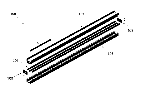
[0031] Figure 1 shows an exploded view of a pressure monitor for attachment
to an edge of
a door leaf;
[0032] Figure 2 shows an end-view of the pressure monitor of Figure 1;
[0033] Figure 3 is a schematic illustration of an alarm system as used in
the pressure
monitor of Figure 1;
[0034] Figures 4A-4C show a door leaf with the pressure monitor of Figure 1
fitted to a
bottom edge thereof.
Detailed description
[0035] Figure 1 shows an exploded view of a pressure monitor 100 for
attachment to an
edge of a door leaf (not shown in Figure 1). The pressure monitor 100 has an
elongate spine
102 for attachment to an edge of a door leaf; elongate ribbon switches 104;
and an elongate
housing 106. End-plates 108 and housing 106 conceal the ribbon switches 104
when the
pressure monitor 100 is assembled, as illustrated in Figure 2. With continued
reference to
Figure 1, the pressure monitor 100 has a longitudinal axis A that extends
along the length of the
pressure monitor 100. The length corresponds to the length of the bottom edge
of the door leaf.
Where elongate components are referred to herein, it is to be understood that
those
components extend in the longitudinal direction A.
[0036] Figure 2 shows an end-view of the pressure monitor 100 of Figure 1
when
assembled, with the end-plates 108 removed to reveal the inner layout of the
pressure monitor
100. Pressure monitor 100 is shown attached to a door leaf 200 in Figure 2.
[0037] The spine 102 has an elongate plate portion 202, and an elongate
hollow box portion
204 which is arranged parallel to the plate portion 202. Spine 102 has a
uniform cross-section
as viewed along the longitudinal axis, and as such is manufactured by
extrusion. The spine 102
-6-
23956353.1
Date Recue/Date Received 2020-08-10
is thus of unitary construction ¨ such that the components of the spine form a
single unitary
piece. The spine is aluminium.
[0038] As shown, plate portion 202 abuts the edge of the door leaf 200,
while elongate
upturned edges 206 abut opposing sides of the door leaf 200, adjacent to the
edge in abutment
with the plate portion 202. The upturned edges 206 help to locate the pressure
monitor 100 at
the edge of the door leaf. They also ensure a substantially flush interface
between the door leaf
200 and the pressure monitor 100. This ensures that no anchor points for a
ligature exist
between the door leaf 200 and the pressure monitor 100.
[0039] Screws (not shown) extend through the plate portion 202 and into the
edge of the
door leaf 200, thus securing the pressure monitor 100 to the door 200. In
alternative
embodiments, screws (not shown) may extend through the upturned edges 206 and
into the
sides door leaf 200.
[0040] The box portion 204 has a first elongate wall 208A, a second
elongate wall 208B and
a third elongate wall 208C. The walls collectively form the box portion 204.
First wall 208A and
second wall 208B are substantially perpendicular with the plate portion 202.
Third wall 208C is
substantially parallel with the plate portion 202. First ribbon switch 104A is
secured within a first
elongate channel that extends along the first wall 208A. Second ribbon switch
104B is secured
within a second elongate channel that extends along the second wall 208B.
Third ribbon switch
104C is secured within a third elongate channel that extends along the third
wall 208C.
Accordingly, when a force is exerted against the first wall 208A, it is
detected by the first ribbon
switch 104A. The same is true of the second ribbon switch 104B, and of the
third ribbon switch
104C.
[0041] As shown, the ribbon switches have a T-shaped cross-section. In
particular, they
have a protrusion that extends in the longitudinal direction and which
protrudes from the
elongate channel. Operation of the ribbon switches is described in further
detail in Figure 3
below.
[0042] With continued reference to Figure 2, the housing 106 has a
generally U-shaped
cross-section as viewed along the longitudinal axis. The cross-section of the
housing is uniform
along the entire longitudinal length of the pressure monitor. As such, the
housing 106 is
manufactured by extrusion. The housing 106 is thus of unitary construction. It
is made of
aluminium.
-7-
23956353.1
Date Recue/Date Received 2020-08-10
[0043] As shown in Figure 2, housing 106 is coupled to the spine 102 so as
to house the
box portion 204 and the ribbon switches 104A-C. First ribbon switch 104A
engages and bears
against a first elongate groove formed in first inner surface 210A of the
housing 106. Second
ribbon switch 104B engages and bears against a second elongate groove formed
in second
inner surface 210B of the housing 106. Third ribbon switch 104C engages and
bears against a
third elongate groove formed in the third inner surface 210C of the housing
106.
[0044] Housing 106 further includes an elongate opening, opposite the third
inner surface
210C, through which the box portion 204 extends into the housing 106. Opening
212 extends
from one longitudinal end of the housing 106 to the other. At the lateral
edges of the opening
are inward-facing elongate lips 212. Lips 212 engage (are received by)
respective recesses
214 between the box portion 204 and the plate portion 202. Accordingly,
separation of the
housing 106 from the spine 102 is prevented. Elongate retaining surfaces 216,
which are part
of the spine 102, also extend along outer side surfaces of the housing 106
adjacent the lips 212.
The retaining surfaces 216 limit (but do not completely prevent) lateral
movement of the housing
106 relative to the spine 104 (where 'lateral' herein means a direction that
is perpendicular to
the longitudinal direction), thereby further preventing separation of the
housing 106 from the
spine 102.
[0045] As mentioned above, Figure 2 shows the pressure monitor without the
end-plate 108
from Figure 1 fitted. As will be appreciated, because of the uniform cross-
sections of the spine
102 and housing 106, there is nothing to prevent the housing 106 from sliding
along the spine
102 in the longitudinal direction. To prevent this from happening, an end-
plate 108 is attached
to each longitudinal end of the pressure monitor. Each end-plate is screwed
into a longitudinal
end of the housing, to conceal the box portion and the ribbon switches
therein. Figures 4A-4B
respectively show an end-view, and a perspective view, of a door leaf 200 and
pressure monitor
100, with end-plates 108 fitted to the pressure monitor 100. Figure 4C shows a
side-view of the
door leaf 200 with pressure monitor 100 fitted.
<dimensions>
[0046] As the skilled person will appreciate, the pressure monitor can have
a variety of
dimensions, dependent on the size of the door leaf to which it is to be
fitted. Nonetheless,
dimensions of an example pressure monitor will now be provided for
illustrative purposes.
[0047] The pressure monitor of Figure 1 has a length, in the longitudinal
direction, of 1m.
That is to say, the spine and the housing each have a length of 992mm, such
that the entire
-8-
23956353.1
Date Recue/Date Received 2020-08-10
pressure monitor has a length of 1m when the end-plates are fitted to the ends
of the housing.
Each pressure sensor has a length of 990mm.
[0048] The pressure switches further have a width of 14.35mm and a height
of 6.90mm.
[0049] The pressure monitor has a depth (in the vertical direction when
fitted to a bottom
edge of a door), from the underside of the housing to a top edge of the
upturned edges, of
44mm. And the pressure monitor has a outer width (in the horizontal direction
when fitted to a
door) of 48mm; and an inner width (as measured from an inner surface of each
upturned edge)
of 45mm. Thus, the pressure monitor having these dimensions is for attachment
to a door leaf
having a bottom edge that is 1m long, and having a thickness of 45mm.
<alert system>
[0050] Figure 3 is a schematic illustration of an alert system 300 as used
in the pressure
monitor of Figures 1, 2 and 4. As shown, alert system 300 is connected to each
of the ribbon
switches 104A-104C. In particular, alarm system comprises a power source 302,
connecting
block 304, and alert interface 306. Alert system 300 is housed within the box
portion 204 of the
pressure monitor 100, although the alert interface of the alert system may be
located outside of
the box portion. Alert system may be configured to issue an audible alert, a
visual alert, or may
comprise a wireless transmission device configured to transmit an alert signal
to a remote
location.
[0051] As depicted, each ribbon switch comprises a casing 308 having a
hollow cavity 310.
Disposed at opposing sides of the hollow cavity are a first electrode 312A and
a second
electrode 312B.
[0052] In a normal (uncompressed) state, as is shown for ribbon switches
104A and 104B,
an air gap exists between the first electrode 312A and the second electrode
312B. In this
uncompressed state, the switches are 'open' ¨ i.e. they do not allow current
to flow.
[0053] However, when a force F is applied to protrusion 314, as is shown
for ribbon switch
104C, the ribbon switch is compressed by the force F. When the force exceeds a
threshold
amount, it will cause the first and second electrodes 312A, 312B to make
contact ¨ thus closing
the switch such that current can flow. When this happens, the circuit between
the battery 302
and the alert interface 306 is completed via the connecting block 204. An
alert is thereby issued
by the alert interface 306 of the alert system 300. A magnitude of the force
required to close
any one of the ribbon switches can be selected as required. Typically, the
force required to
-9-
23956353.1
Date Recue/Date Received 2020-08-10
close any one of the ribbon switches may be selected as approximately 68N
(i.e. a force that is
roughly equivalent the gravitational pull on a mass of 7kg).
[0054] Similarly, if more than one of the ribbon switches are closed, an
alert will be issued.
Only one of the ribbon switches is required to be closed for an alert to be
issued.
<mode of operation>
[0055] Operation of the pressure sensor 100 of Figures 1-4 will now be
described.
[0056] When fitted to a door frame (not shown), the bottom of edge of the
door leaf 200 (to
which the pressure monitor 100 is attached) will sit close to the floor. By
carefully fitting the
door leaf 200 to the door frame, it is possible to ensure that the separation
between the
underside of the pressure monitor 100 and the floor is very small.
Nonetheless, a small amount
of clearance between the door frame and the floor is necessary to ensure that
the door leaf can
move to open and close the door. The applicant has found that even the
smallest amount of
clearance between a door leaf and the floor can be enough for an individual to
pass a cable
under the door leaf to create a ligature.
[0057] It is for this reason that the pressure monitor is attached to the
bottom edge of the
door. In order to anchor a ligature around the bottom edge of the door leaf
200 in Figs. 3, a
cable has to be looped around the underside of the pressure monitor 100. When
a cable is
looped around the underside of the pressure sensor in Figs. 3, and a tension
is applied to the
cable, the cable will in turn exert a force F on the housing 106 of the
pressure monitor 100.
Depending on how the cable is secured, it could exert a force in any number of
directions. The
force could be applied in a first horizontal direction F1 (towards the right
in Figure 4A) or in a
second horizontal direction F2 that is opposite to the first horizontal
direction (towards the left in
Figure 4A), or in a vertical direction F3 (upwards in Figure 4A). Or the force
could be applied in
a combination of the first horizontal direction F1 and the vertical direction
F3. Or the force could
be applied in a combination of the second horizontal direction F2 and the
vertical direction F3.
[0058] Whichever direction the force is applied in, it will cause a
corresponding movement
of the housing 106 relative to the spine 102. For example, if the force is
applied in the first
horizontal direction F1, it will cause movement of the housing to the right.
Accordingly, the first
inner surface 210A of the housing will move towards the first wall 208A of the
box portion 204;
which in turn will compress the first ribbon switch 104A against the inner
surface 210A of the
housing. Accordingly, the electrical resistance of the first ribbon switch
104A will change due to
- 10 -
23956353.1
Date Recue/Date Received 2020-08-10
this compression (pressure). Once the magnitude of F1 reaches a threshold
level, the change
in resistance of the ribbon switch 104A will reach a predetermined threshold,
thereby causing
the alert system to issue the alert signal.
[0059]
It is to be understood that the above description is intended to be
illustrative, and not
restrictive. Many other implementations will be apparent to those of skill in
the art upon reading
and understanding the above description. Although the present disclosure has
been described
with reference to a specific example implementation, it will be recognized
that the disclosure is
not limited to the implementations described, but can be practiced with
modification and
alteration insofar as such modification(s) and alteration(s) remain within the
scope of the
appended claims. Accordingly, the specification and drawings are to be
regarded in an
illustrative sense rather than a restrictive sense. The scope of the
disclosure should, therefore,
be determined with reference to the appended claims, along with the full scope
of equivalents to
which such claims are entitled.
-11-
23956353.1
Date Recue/Date Received 2020-08-10