Note: Descriptions are shown in the official language in which they were submitted.
CA 03090124 2020-07-30
WO 2019/152779
PCT/US2019/016250
PCT INTERNATIONAL PATENT APPLICATION
PIPE COIL SKID WITH SIDE RAILS AND METHOD OF USE
1
[0001]
BACKGROUND
[0002] Flexible pipe is useful in a myriad of environments, including in
the oil and gas
industry. Flexible pipe may be durable and operational in harsh operating
conditions and can
accommodate high pressures and temperatures. Flexible pipe may be bundled and
arranged into
one or more coils to facilitate transporting and using the pipe.
[0003] Coils of pipe may be positioned in an "eye to the side" or "eye to
the sky"
orientation. When the flexible pipe is coiled and is disposed with its
interior channel facing
upwards, such that the coil is in a horizontal orientation, then the coils of
pipe are referred to as
being in an "eye to the sky" orientation. If, instead, the flexible pipe is
coiled and disposed such
that the interior channel is not facing upwards, such that the coil is in an
upright or vertical
orientation, then the coils of pipe are referred to as being in an "eye to the
side" orientation.
100041 The flexible pipe may be transported as coils to various sites for
deployment (also
referred to as uncoiling or unspooling). Different types of devices and
vehicles are currently
used for loading and transporting coils of pipe, but usually extra equipment
and human manual
labor is also involved in the process of loading or unloading such coils for
transportation and/or
deployment. Such coils of pipe are often quite large and heavy. Accordingly,
there exists a need
for an improved method and apparatus for loading, moving and unloading coils
of pipe.
2
Date Recue/Date Received 2022-04-04
SUMMARY
[0005] Various nonlimiting embodiments provide methods and apparatuses for
moving
coils of flexible pipe using a pipe coil skid with side rails. A pipe coil
skid includes a plurality of
beams affixably connected together to form a rectangular shaped base with a
platform disposed
within the base, the platform having a concave upward shape on its upward
facing side when the
skid sits on a horizontal surface such that the coil of pipe positioned upon
the platform contacts
the platform within the base. In other aspects, the pipe coil skid has an
upward facing side
generally corresponding to the outer circumferential shape of a coil of pipe.
The beams and the
platform may be formed of a steel material. The platform may be coated with a
non-stick
material or a rubberized material. The pipe coil skid may have a plurality of
tie-down points for
securing the coil of pipe. The pipe coil skid may have stackable corners
disposed on the skids to
enable stacking of pipe coil skids. The pipe coil skid may include a first
side rail coupled to at
least one of the plurality of beams. The side rails may be configured to block
movement of the
coil of pipe beyond a boundary of the rectangular shaped base.
[0006] In other nonlimiting embodiments, a method for using a pipe coil
skid with side rails
includes: securing a coil of pipe to a pipe coil skid, the skid comprising a
plurality of beams
affixably connected together to form a rectangular shaped base, and a platform
disposed within
the base, the platform having a concave upward shape on its upward facing side
when the skid
sits on a horizontal surface, such that the coil of pipe positioned upon the
platform contacts the
platform within the base. The coil may be lifted using a pipe coil lifting
device disposed on a
forklift, a pipe coil lifting device secured by cable to a crane, an
installation trailer for coiled
pipe, or an expandable drum assembly for deploying coiled pipe. The skid may
have an upward
facing side generally corresponding to the outer circumferential shape of a
coil of pipe. The
3
Date Recue/Date Received 2022-04-04
beams and the platform are formed of a steel material and the platform may be
coated with a
non-stick material or a rubberized material. The pipe coil is secured to the
skid using straps.
The coil and skid may be secured to a rail car. The skids may be stacked. The
pipe coil skid may
include a first side rail coupled to at least one of the plurality of beams.
The method may include
blocking movement of the coil of pipe beyond a boundary of the rectangular
shaped base via the
first side rail.
[0007] In other nonlimiting embodiments, a side rail includes a first
vertical leg that
includes a first end configured to be inserted into a first slot of a pipe
coil skid and a second end
coupled near a first end of a horizontal restraint beam. The first vertical
leg includes a first leg
height greater than approximately 25 percent of a diameter of a coil of pipe
positioned upon the
pipe coil skid. The side rail also includes a second vertical leg that
includes a first end configured
to be inserted into a second slot of the pipe coil skid and a second end
coupled near a second end
of the horizontal restraint beam. The second vertical leg includes a second
leg height greater than
approximately 25 percent of the diameter of the coil of pipe, and the
horizontal restraint beam
includes a restraint beam length that is greater than the diameter of the coil
of pipe. The side rail
also includes a horizontal support beam that includes a first end coupled near
the second end of
the first vertical leg and a second end coupled near the second end of the
second vertical leg. The
horizontal support beam includes a support beam length approximately equal to
a base length of
the rectangular shaped base.
[0007a] In another embodiment, there is provided a system, comprising a
pipe coil skid,
wherein the pipe coil skid comprises: a plurality of beams affixably connected
together to form a
rectangular shaped base; a platform disposed within the rectangular shaped
base, wherein the
platform comprises a concave upward facing side when the pipe coil skid sits
on a horizontal
4
Date Recue/Date Received 2022-04-04
surface to enable a coil of pipe to contact the platform within the
rectangular shaped base; and a
first side rail configured to be coupled to a first side of the rectangular
shaped based to facilitate
blocking movement of the coil of pipe beyond a boundary of the rectangular
shaped base,
wherein the first side rail comprises: a first vertical leg configured to be
coupled to the
rectangular shaped base; a second vertical leg configured to be coupled to the
rectangular shaped
base; and a horizontal restraint beam secured to a first upper end of the
first vertical leg and a
second upper end of the second vertical leg such that the horizontal restraint
beam extends
horizontally beyond the first vertical leg and the second vertical leg.
10007b1 In another embodiment, there is provided a method for using a
system that includes
a pipe coil skid, comprising: disposing a coil of pipe on the pipe coil skid,
wherein the pipe coil
skid comprises: a plurality of beams affixably connected together to form a
rectangular shaped
base; a platform disposed within the rectangular shaped base, wherein the
platform comprises a
concave upward facing side when the pipe coil skid sits on a horizontal
surface to enable the coil
of pipe to contact the platform within the rectangular shaped base; and a side
rail coupled to a
side of the rectangular shaped base, wherein the side rail comprises: a first
vertical leg coupled to
the rectangular shaped base; a second vertical leg coupled to the rectangular
shaped base; and a
horizontal restraint beam secured to a first upper end of the first vertical
leg and a second upper
end of the second vertical leg such that the horizontal restraint beam extends
horizontally beyond
the rectangular shaped base; and blocking movement of the coil of pipe beyond
a boundary of
the rectangular shaped base using at least the side rail.
[00070 In another embodiment, there is provided a system comprising a side
rail configured
to be coupled to a rectangular shaped base of a pipe coil skid, wherein the
side rail comprises: a
Date Recue/Date Received 2022-04-04
first vertical leg, wherein the first vertical leg comprises a first lower end
configured to be
inserted into a first slot that is secured to the rectangular shaped base of
the pipe coil skid to
facilitate coupling the side rail to the rectangular shaped base of the pipe
coil skid; a second
vertical leg, wherein the second vertical leg comprises a second lower end
configured to be
inserted into a second slot that is secured to the rectangular shaped base of
the pipe coil skid to
facilitate coupling the side rail to the rectangular shaped base of the pipe
coil skid; a horizontal
support beam secured between the first vertical leg and the second vertical
leg; and a horizontal
restraint beam secured to a first upper end of the first vertical leg and a
second upper end of the
second vertical leg above the horizontal support beam, wherein the horizontal
restraint beam
comprises a restraint beam length that is longer than a support beam length of
the horizontal
support beam.
BRIEF DESCRIPTION OF THE DRAWINGS
[0008] A better understanding of the present invention can be obtained when
the following
detailed description of the preferred embodiment is considered in conjunction
with the following
drawings, in which:
100091 FIG. 1 is a diagram of a coil of pipe secured with straps on a pipe
coil skid according
to embodiments of the present disclosure;
1000101 FIG. 2 is an illustration of a coil of pipe on a pipe coil skid
according to
embodiments of the present disclosure;
6
Date Recue/Date Received 2022-04-04
[00011] FIG. 3 illustrates a pipe coil skid according to embodiments of the
present
disclosure;
[00012] FIG. 4 illustrates a pipe coil skid according to embodiments of the
present
disclosure;
[00013] FIG. 5 illustrates aspects of a pipe coil skid according to
embodiments of the present
disclosure;
[00014] FIG. 6 illustrates aspects of a pipe coil skid according to
embodiments of the present
disclosure;
[00015] FIG. 7 illustrates aspects of a pipe coil skid according to
embodiments of the present
disclosure;
[00016] FIG. 8 illustrates aspects of a pipe coil skid according to
embodiments of the present
disclosure;
[00017] FIG. 9 illustrates aspects of a pipe coil skid according to
embodiments of the present
disclosure;
[00018] FIG. 10 illustrates aspects of a pipe coil skid according to
embodiments of the
present disclosure;
[00019] FIG. 11 illustrates aspects of a pipe coil skid according to
embodiments of the
present disclosure;
[00020] FIG. 12 illustrates aspects of a pipe coil skid according to
embodiments of the
present disclosure;
7
Date Recue/Date Received 2022-04-04
[00021] FIG. 13 illustrates aspects of a pipe coil skid according to
embodiments of the
present disclosure;
100022] FIG. 14 illustrates aspects of a pipe coil skid according to
embodiments of the
present disclosure;
[00023] FIG. 15 illustrates aspects of a pipe coil skid according to
embodiments of the
present disclosure;
[00024] FIG. 16 illustrates aspects of a pipe coil skid according to
embodiments of the
present disclosure.
[00025] FIG. 17 illustrates aspects of a pipe coil skid to be used with
side rails according to
embodiments of the present disclosure.
100026] FIG. 18 illustrates aspects of a pipe coil skid to be used with
side rails according to
embodiments of the present disclosure.
[00027] FIG. 19 illustrates aspects of a pipe coil skid to be used with
side rails according to
embodiments of the present disclosure.
[00028] FIG. 20 illustrates aspects of a pipe coil skid to be used with
side rails according to
embodiments of the present disclosure.
[00029] FIG. 21 illustrates aspects of a side rail to be used with a pipe
coil skid according to
embodiments of the present disclosure.
[00030] FIG. 22 illustrates aspects of a side rail to be used with a pipe
coil skid according to
embodiments of the present disclosure.
8
Date Recue/Date Received 2022-04-04
[00031] FIG. 23 illustrates aspects of a side rail to be used with a pipe
coil skid according to
embodiments of the present disclosure.
[00032] FIG. 24 illustrates aspects of a side rail to be used with a pipe
coil skid according to
embodiments of the present disclosure.
[00033] FIG. 25 illustrates aspects of a side rail to be used with a pipe
coil skid according to
embodiments of the present disclosure.
[00034] FIG. 26 illustrates aspects of a pipe coil skid with side rails
according to
embodiments of the present disclosure.
[00035] FIG. 27 illustrates aspects of a pipe coil skid with side rails
according to
embodiments of the present disclosure.
[00036] FIG. 28 illustrates aspects of a pipe coil skid with side rails
according to
embodiments of the present disclosure.
9
Date Recue/Date Received 2022-04-04
CA 03090124 2020-07-30
WO 2019/152779 PCT/US2019/016250
DETAILED DESCRIPTION
[00037] Embodiments of the present disclosure relate generally to a pipe
coil skid with side
rails for use in transporting, storing and/or deploying coils of pipe. Coils
of pipe may be self
supported, for example, using straps or bands to hold coils together, or coils
of pipe may be
supported around a reel (which may be referred to as a reel of pipe).
[00038] Embodiments of the present disclosure will be described below with
reference to the
figures. In one aspect, embodiments disclosed herein relate to embodiments for
pipe coil skids of
various sizes configured for use in storage, deployment or transporting coils
of flexible pipe to
various sites.
[00039] As used herein, the term "coupled" or "coupled to" may indicate
establishing either a
direct or indirect connection, and is not limited to either unless expressly
referenced as such. The
term "set" may refer to one or more items. Wherever possible, like or
identical reference
numerals are used in the figures to identify common or the same elements. The
figures are not
necessarily to scale and certain features and certain views of the figures may
be shown
exaggerated in scale for purposes of clarification.
[00040] FIG. 1 shows a diagram of a coil of pipe 102 disposed on a pipe
coil skid 106, the
coil of pipe 102 secured by straps 12 or bands to tie-down points 2 according
to embodiments of
the present disclosure.
[00041] As illustrated in FIG. 2, coil of pipe 102 may be formed by
wrapping pipe into a coil
with an interior channel 104 foimed axially therethrough, where the coil of
pipe 102 may be
moved as a single package or bundle of coiled pipe, as shown in FIG. 1. Each
complete turn of
CA 03090124 2020-07-30
WO 2019/152779 PCT/US2019/016250
coiled pipe may be referred to as a wrap of pipe. Multiple wraps of pipe in a
coil of pipe may be
configured in columns along an axial dimension of the coil of pipe and/or
configured in layers
along a radial dimension of the coil of pipe For example, multiple columns of
wraps may be
formed along an axial direction of the coil of pipe, where the axial dimension
of the coil of pipe
is based on the diameter of the pipe and the number and axial position of
wraps forming the coil
of pipe 102. Further, multiple layers of wraps may be formed along a radial
direction of the coil
of pipe, where the radial dimension of the coil of pipe is based on the
diameter of the pipe and
the number and radial position of the wraps forming the coil of pipe.
[00042] As shown in FIG. 2, coil of pipe 102 may be one or more layers
(e.g., layers 108 and
110) of pipe packaged or bundled into a larger coil. Coil of pipe 102 may
include at least one or
more layers of pipe that have been coiled into a particular shape or
arrangement. As shown in
FIG. 2, coil of pipe 102 is coiled into a substantially cylindrical shape
having substantially
circular bases 103 and 105 formed on each end of coil of pipe 102, where the
axial dimension of
coil of pipe 102 is measured between the two bases 103, 105.
[00043] A pipe, as understood by those of ordinary skill, may be a tube to
convey or transfer
any water, gas, oil, or any type of fluid known to those skilled in the art.
The pipe used to make
up coil of pipe 102 may be made of any type of materials including without
limitation plastics,
metals, a combination thereof, composites (e.g., fiber reinforced composites),
or other materials
known in the art.
[00044] In one or more embodiments, the pipe used to make up coil of pipe
102 may be a
flexible type of pipe. Flexible pipe is used frequently in many applications,
including without
limitation, both onshore and offshore oil and gas applications. Flexible pipe
may include Bonded
11
CA 03090124 2020-07-30
WO 2019/152779 PCT/US2019/016250
or Unbonded Flexible Pipe, Flexible Composite Pipe (FCP), Thermoplastic
Composite Pipe
(TCP) or Reinforced Thermoplastic Pipe (RTP). A FCP/RTP pipe may itself be
generally
composed of several layers. In one or more embodiments, a flexible pipe may
include a high-
density polyethylene ("HDPE") liner having a reinforcement layer and an HDPE
outer cover
layer. Additionally, various types of polyethylene are available for flexible
pipe composition.
Other polymers may also be used such as nylon, PVDF, polypropylene and many
others. Thus,
flexible pipe may include different layers that may be made of a variety of
materials and also
may be treated for corrosion resistance. For example, in one or more
embodiments, pipe used to
make up a coil of pipe may have a corrosion protection shield layer that is
disposed over another
layer of steel reinforcement. In this steel reinforced layer, helically wound
steel strips may be
placed over a liner made of thermoplastic pipe Flexible pipe may be designed
to handle a variety
of pressures, temperatures, and conveyed fluids. Further, flexible pipe may
offer unique features
and benefits versus steel or carbon steel pipe lines in the areas of corrosion
resistance, flexibility,
installation speed, and re-usability. Another type of spoolable pipe is coiled
tubing. Coiled tubing
may be made of steel. Coiled tubing may also have a corrosion protection
shield layer.
[00045] Coils of pipe may be made with coil having an outer diameter
ranging, for example,
from about 2 inches (5.1 cm) to about 10 inches (25.4 cm). However, pipe
having other
dimensions may be coiled to form a coil of pipe according to embodiments of
the present
disclosure. Accordingly, pipe that that may be spooled or coiled into coil of
pipe 102 may be
made to suit a number of dimensions and may have any diameter useful to a
particular project.
[00046] As known to those of ordinary skill in the art, pipe used to make
up coil of pipe 102
may be coiled using spoolers or other coiler machines suited for such a
function. Those of
ordinary skill will recognize that the present disclosure is not limited to
any particular form of
12
CA 03090124 2020-07-30
WO 2019/152779 PCT/US2019/016250
coiler or other device that may be used to form pipe into a coil. Coiling pipe
into a coil of pipe,
such as 102, assists when transporting pipe, which may be several hundred feet
in length in one
or more embodiments. Further, coil of pipe 102 may be assembled as a coil to
facilitate
deployment of the coil. Deployment, as described above and used herein, may
refer to the action
of unspooling or unwinding the pipe from coil of pipe 102.
[00047] After being assembled into a coil, coil of pipe 102 may include an
interior channel
104 formed axially through the coil of pipe 102. Interior channel 104 is a
bore disposed generally
in the center of coil of pipe 102. Interior channel 104 is substantially
circular shaped. The coil of
pipe 102 may have an outer diameter (OD) and an inner diameter (ID), where the
inner diameter
is defined by the interior channel.
[00048] In one or more embodiments, coil of pipe 102 may have an outer
diameter ranging
from about 60 inches (1.5 m), which may occur, for example, when coil of pipe
102 has at least
two layers of 2 inch pipe, to about 192 inches (4.9 m). In one or more
embodiments, a coil of
pipe may have an inner diameter ranging, for example, from about 84 inches
(2.1 m) to about
126 inches (3.2 m). Further, in one or more embodiments, a coil of pipe may
have an axial
dimension (width) ranging from about 5 inches (12.7 cm) to about 92 inches
(2.3 m). However,
these are merely exemplary measurements. Those of ordinary skill in the art
will appreciate that
any range of dimensions (inner and outer diameters and width) may be
accommodated using one
or more embodiments.
[00049] Various illustrative embodiments of skid 106 and its related
equipment and
information are shown in FIGS. 1-31 herein. Skid 106 illustrated in FIGS. 1-31
may comprise a
platform 4 upon which coil of pipe 102 may be disposed to hold the coil of
pipe 102 in a vertical
13
CA 03090124 2020-07-30
WO 2019/152779 PCT/US2019/016250
orientation. In one or more embodiments, coil of pipe 102 may be moved and
secured while
remaining on skid 106.
[00050] As illustrated in FIG. 3 and FIG. 4 according to certain
illustrative embodiments,
skid 106 can be formed of a plurality of beams 1, 3, 6, and 7 that are affixed
together to form a
rectangular shaped base. In certain illustrative embodiments, the base may be
square shaped. A
platform 4 sits within the base. The platform 4 can have a concave curvature
shape on its
upward facing side (when skid 106 sits on a horizontal surface) that generally
corresponds to the
outer circumferential shape of coil of pipe 102, such that when coil of pipe
102 sits within the
base of the pipe coil skid 106, it is generally flush with the platform 4.
However, the above
description should not be deemed limiting with respect to the shape,
construction, or application
of skid 106, as skid 106 may have any shape, construction, and/or application
that is within the
scope of the description and figures herein. The pipe coil skid 106 may
contain weep holes 11,
for example through beam 1 as shown in FIG. 3, to aid in the removal of water
from the interior
of the skid 106. A cross-sectional view of beam 1 is shown in FIG. 8.
[00051] Additionally, as illustrated in FIG. 4 and FIG. 6, the platform 4
may have attached a
plurality of u-channels 6 or u-beams as further supporting structure. Larger
skids 106 may have
more u-channels 6 to provide additional support of the platform 4 and coil of
pipe 102. A cross
section detail of this u-channel 6 structure is illustrated in FIG. 11. In
certain cases, beams may
be other structural shapes, for example, rectangular tube, square tube, I-
beam, T-beam, or other
common structural forms.
[00052] In certain illustrative embodiments, skid 106 can be formed of a
metal material. For
example, the metal material can be A572/GR 50 high strength, low alloy
columbium vanadium
14
CA 03090124 2020-07-30
WO 2019/152779 PCT/US2019/016250
structural steel. Any metal capable of supporting 40,000 lb (18,144 kg) loads
may also be used
including equivalent available metals such as ISO spec metal, ASTM and AISI
metals.
[00053] In certain illustrative embodiments, the metal skid can be
constructed of structural
steel components such as c-channels, angle iron, or sheet metal that are
welded together. The
skid can be utilized to secure coil of pipe 102 so that it does not roll away
or get damaged during
storage and/or transport.
[00054] In certain illustrative embodiments, the platform and/or other
parts of the metal skid
can be coated with a non-stick material, and/or rubberized material, or
otherwise have a non-
stick surface such that coil of pipe 102 is prevented from slipping off of the
skid.
[00055] In certain illustrative embodiments, skid 106 may be sized with an
upward facing
concave surface to support coil of pipe 102 that may have an outside diameter
(OD) of about 192
inches and a weight of about 40,000 lb (18,144 kg). However, skid 106 can be
sized as needed
to transport different sizes and/or weights of coiled pipe.
[00056] Also with respect to FIGS. 3 and 4, skid 106 can have one or more
fork pockets or
channels 8 so that skid 106 can be lifted and moved with a forklift (see,
e.g., FIGS. 3-4). Skid
106 may also have one or more tie-down points 2 (such as lashing rings, see
FIGS. 3, 5, 7, 10
and 12) disposed thereon to secure the coiled pipe 102 to the skid 106 with,
for example, straps
12 (see, e.g., FIGS. 1, 12, and 13). The tie down points 2 may be disposed on
an angled surface
that meets platform surface 4 (see, e.g., FIG. 12). Skid 106 may also have
stackable corners 9,
so that the skids can be stacked during transport or storage (see, e.g., FIGS.
3-10 and 16).
The stackable corners 9, 10 can also be designed to fit securely within the
brackets on a rail
CA 03090124 2020-07-30
WO 2019/152779 PCT/US2019/016250
trailer so that the skid (or stack of skids) will be secured to the trailer
during rail transport. Skid
106 can also be sized such that it can fit in a standard over-seas shipping
container.
[00057] FIG. 13 shows pipe coil 102 secured to pipe coil skid 106 with
straps 12. FIG. 1
illustrates pipe coil 102 on pipe coil skid 106. It should be appreciated that
a pipe coil 102 with a
pipe coil skid 106 attached may be moved using a forklift or crane that is not
in contact with the
pipe coil skid. At the same time, the coil 102 with skid 106 package could be
lifted via skid
pockets with adequately sized pocket dimensions assuming a lift with adequate
weight capability
is used. The design of the skid 106 may be limited due to space availability
under the support
surface of the skid and still ensure the overall package size fits with
standard cargo containers. In
certain embodiments, the pipe coil skid 106 may include various features to
enable the pipe coil
skid 106 to be used with various side rails as described in detail below.
[00058] FIG. 17 illustrates a top view of an embodiment of the pipe coil
skid 106. In the
illustrated embodiment, the pipe coil skid 106 includes four slots 120 coupled
to the four corners
of the pipe coil skid 106. In other embodiments, the slots 120 may be located
at other locations,
such as along sides of the pipe coil skid 106, and there may be one, two,
three, five or more slots
120 depending on the configuration of the side rails described in detail
below. In certain
embodiments, the slots 120 may be made from steel plate bent into a tubular
shape and coupled
to the pipe coil skid 106 using a variety of techniques, such as welding,
brazing, or threaded
connectors. In some embodiments, the slots 120 may be integral components of
the beams 1, 3,
6, and 7 of the pipe coil skid 106. The slots 120 may have a cross-section
shape that corresponds
to a square, rectangle, triangle, polygon, circle, oval, or other appropriate
shape. As described
below, the slots 120 may be sized to enable legs of side rails to be inserted
into the slots 120. In
16
CA 03090124 2020-07-30
WO 2019/152779 PCT/US2019/016250
other respects, the pipe coil skid 106 shown in FIG. 17 is similar to
embodiments previously
described and shown in the figures.
[00059] FIG. 18 illustrates a side view of an embodiment of the pipe coil
skid 106 with slots
120. As shown in FIG. 18, the slots 120 may have a height 130 approximately
the same as a
height 140 of the pipe coil skid 106. In other embodiments, the height 130 of
the slots 120 may
be less than or greater than the height 140 of the pipe coil skid 106
depending on the amount of
support to be provided to the side rails.
[00060] FIG. 19 illustrates a close-up side view of an embodiment of the
slots 120 coupled to
the pipe coil skid 106. For example, a flat bar 150 may be coupled between the
slots 120 and the
pipe coil skid 106. In other embodiments, the slots 120 may be coupled
directly to the pipe coil
skid 106.
[00061] FIG. 20 illustrates a close-up top view of an embodiment of the
slots 120 coupled to
the pipe coil skid 106. As shown in FIG. 20, flat bar 150 is coupled between
the slot 120 and the
pipe coil skid 106, although in certain embodiments, the flat bar 150 may be
omitted. In certain
embodiments, a weep hole 152 may be provided in the slot 120 to help prevent
the buildup of
rainwater or other liquids.
[00062] FIG. 21 illustrates a side view of an embodiment of a side rail 160
that may be used
with the pipe coil skid 106 shown in FIGS. 17-20. In the illustrated
embodiment, the side rail 160
includes a first vertical leg 170, a second vertical leg 180, a horizontal
restraint beam 190, and a
horizontal support beam 200 all coupled to one another to provide the
structure of the side rail
160. In other embodiments, the components of the side rail 160 may be coupled
together in
different arrangements. For example, certain embodiments of the side rail 160
may include a
17
CA 03090124 2020-07-30
WO 2019/152779 PCT/US2019/016250
different number of vertical legs, such as one, three, four or more legs.
Similarly, certain
embodiments of the side rail 160 may include a different number of horizontal
restraint beams
190 or horizontal support beams 200. Further, although the components of the
side rail 160 may
be described as having vertical or horizontal orientations, it is understood
that in certain
embodiments, the components may be arranged at other angles with respect to
the pipe coil skid
106. In addition, although the components of the side rail 160 are shown as
generally straight in
FIG. 21, they may have other shapes in certain embodiments. For example, the
horizontal
restraint beam 190 or horizontal support beam 200 may have a V-shape. The
first and second
vertical legs 170 and 180 may have shapes generally corresponding to those of
the slots 120 to
enable the first and second vertical legs 170 and 180 to be inserted into the
slots 120. In certain
embodiments, the first and second vertical legs 170 and 180 may be detachably
coupled to the
slots 120. In some embodiments, additional techniques, such as pins, may be
used to secure the
first and second vertical legs 170 and 180 to the slots. In other embodiments,
the first and second
vertical legs 170 and 180 may be coupled to the slots 120 via welding or
brazing.
[00063] In certain embodiments, one or more forklift pockets 210 may be
used for handling
the side rail 160 and/or pipe coil skid 106 as shown in FIG. 21. In some
embodiments, one or
more lashing rings 220 may be used to handle or secure the side rail 160, such
as via straps,
cables, ropes, and so forth. In further embodiments, the side rail 160 may
include one or more
rings 230 or openings 240 configured to accept a chain or rope used to secure
the pipe coil skid
106. The rings 230 and openings 240 may be located at any convenient locations
of the side rail
160. In certain embodiments, additional supports 250 may be included to
provide additional
structural stability for the side rail 160. In further embodiments, the side
rail 160 may include
one or more tabs 252 that may be used to facilitate stacking of a plurality of
side rails 160, such
18
CA 03090124 2020-07-30
WO 2019/152779 PCT/US2019/016250
as when new side rails 160 are delivered or when side rails 160 are returned
after being used for
transportation of the pipe coil 102. The horizontal support beam 200 of one
side rail 160 may
contact the tab 252 of a second side rail 160 to prevent relative movement of
the two side rails
160. In yet further embodiments, the side rail 160 may include one or more
corners 254 that may
also be used to facilitate stacking of a plurality of side rails 160. The
horizontal restraint beam
190 of one side rail 160 may contact the corner 254 of a second side rail 160
to prevent relative
movement of the two side rails 160 When the side rails 160 include both the
tab 252 and the
corners 254, a plurality of side rails 160 may be prevented from any relative
movement when
stacked together.
[00064] The side rail 160 may be used with the pipe coil skid 106 to block
movement of the
coil of pipe 102 beyond a boundary of the rectangular shaped base of the pipe
coil skid 106. In
other words, the side rail 160 may help contain the coil of pipe 102 within
the boundary of the
rectangular shaped base of the pipe coil skid 106. In some situations, the
coil of pipe 102 may
undergo shifting, leaning, or other movement during transportation. By having
the side rail 160
in close proximity to or touching the circular bases 103 and 105, the coil of
pipe 102 is blocked
or prevented from moving beyond the boundary of the rectangular shaped base of
the pipe coil
skid 106, which may help comply with certain transportation guidelines, rules,
or regulations.
[00065] FIG. 22 illustrates a top view of the embodiment of the side rail
160 shown in FIG.
21. FIG 23 illustrates a bottom view of the embodiment of the side rail 160
shown in FIG. 21.
FIG. 24 illustrates a front view of the embodiment of the side rail 160 shown
in FIG. 21. Finally,
FIG. 25 illustrates a perspective view of the embodiment of the side rail 160
shown in FIG. 21.
Elements in common with those shown in FIG. 21 are labeled with the same
reference numerals
in FIGS. 22-25.
19
CA 03090124 2020-07-30
WO 2019/152779 PCT/US2019/016250
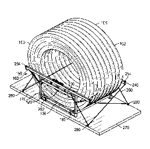
[00066] FIG. 26 illustrates a perspective view of an embodiment of the pipe
coil skid 106,
side rail 160, and coil of pipe 102. As shown in FIG. 26, two side rails 160
are located at the
sides of the pipe coil skid 106 forming a space therebetween where the coil of
pipe 102 is
located. In the illustrated embodiment, one or more chains 260 are used to
secure the side rail
160 to a rail car 270 or other transportation platform, such as a truck or
deck of a vessel or ship.
As shown in FIG. 26, the chains 260 may pass through the openings 240 or
through other
portions of the side rail 160 to secure the side rail 160 to tie-down points
280 of the rail car 270.
For example, portions of the chains 260 may rest against the first vertical
leg 170, second vertical
leg 180, horizontal restraint beam 190, horizontal support beam 200, or other
portions of the side
rail 160. As shown in FIG. 26, the horizontal restraint beam 190 of the first
side rail 160 may
contact the circular base 103 of the coil of pipe 102 to block movement of the
coil of pipe 102
beyond the boundary of the pipe coil skid 106. Similarly, the horizontal
restraint beam 190 of the
second side rail 160 may contact the circular base 105 of the coil of pipe 102
to block movement
of the coil of pipe 102 beyond the boundary of the pipe coil skid 106. Thus,
the coil of pipe 102
(i.e., one or more layers 108, 110 of the coil of pipe 102) is prevented from
extending beyond the
boundary of the pipe coil skid 106, such as by leaning to one side. This may
help prevent any
part of the coil of pipe 102 from contacting objects located beyond the rail
car 270 during
transportation. In certain embodiments, coil-contacting components, such as
blocks of plastic of
foam, may be added to the inner surfaces of the horizontal restraint beams 190
to prevent any
potential damage to the coil of pipe 102 during transportation.
[00067] FIG. 27 illustrates a side view of an embodiment of the pipe coil
skid 106, side rail
160, and coil of pipe 102. As shown in FIG. 27, the side rail has a rail
height 290 that is greater
than approximately 25 percent of a diameter 300 of the coil of pipe 102. In
addition, the side rail
CA 03090124 2020-07-30
WO 2019/152779 PCT/US2019/016250
150 has a rail length 310 that is approximately equal to or greater than the
diameter 300 of the
coil of pipe 102. By providing the side rail 160 with the rail height 290 and
rail length 310, the
side rail 160 may have enough support area to block movement of the coil of
pipe 102 beyond a
boundary of the rectangular shaped base of the pipe coil skid 106. In further
embodiments, the
rail height 290 may be greater than approximately 30, 40, 50, 60, or 70
percent of the diameter
300. In yet further embodiments, the rail length 310 may be less than the
diameter 300 when the
rail height 290 is tall enough to provide sufficient support area to block
movement of the coil of
pipe 102 beyond a boundary of the rectangular shaped base of the pipe coil
skid 106.
[000681 FIG. 28 illustrates a front view of an embodiment of the pipe coil
skid 106, side rail
160, and coil of pipe 102. As shown in FIG. 28, the chains 260 may cross over
one another to
provide additional stability when securing the side rail 160 to the rail car
270. In addition, it can
be seen in FIG. 28 how the side rails 160 physically block movement of the
coil of pipe 102
beyond a boundary of the pipe coil skid 106. Further, although one arrangement
of chains 260 is
shown in the figures, it is anticipated that the coil of pipe 102 can be
secured using a variety of
different arrangements of chains 260 or using other shipping materials, such
as straps, ropes, and
so forth.
[00069] Numerous benefits and advantages may be provided as a result of the
one or more
embodiments of a steel pipe coil skid 106 as described in the present
disclosure. For example, in
certain illustrative embodiments, skid 106 can have a size, shape and
construction that is
acceptable by freight railroad transportation providers to safely handle the
2g and 3g loading
requirements for shipping large, heavy items on the rail. Skid 106 having a
metal construction
is especially suited for transporting the coil of pipe 102 by rail. Prior art
skid designs made of
wood could not be transported by rail because they could not meet these 2g
lateral and 3g
21
CA 03090124 2020-07-30
WO 2019/152779 PCT/US2019/016250
longitudinal loading requirements. In addition, while rail transportation
often requires
hardwood construction of transportation skids, which is costly, the metal
fabricated design is
overall cheaper and stronger.
[00070] For example, when a reel is not utilized, i.e., reel-less pipe, the
coil of pipe 102 can
include a very long length of wound piping and be heavier (and longer) than
reeled pipe.
Certain customers may desire that pipe 102 not be coiled onto a reel because
reels must then be
stored and/or returned to the supplier after the pipe 102 is removed. Skid 106
may also be
transported by truck, train or ship, if desired. Thus, skid 106 is multi-modal
in certain illustrative
embodiments.
[00071] In certain illustrative embodiments, one or more brackets can be
utilized on or near
the rails of the railcar to further secure skid 106 to the railcar. In certain
illustrative
embodiments, the brackets can be positioned on both sides of skid 106 to
provide support on
each side, and pressed tightly against skid 106 such that movement of skid 106
is restricted. The
brackets can have a length that is the same length as, or substantially the
same length as, the skid,
or alternatively, one or more shorter brackets can be utilized along the
length of the skid.
[00072] In one nonlimiting embodiment a pipe coil skid with side rails
includes a plurality of
beams affixably connected together to form a rectangular shaped base with a
platform disposed
within the base, the platform having a concave upward shape on its upward
facing side when the
skid sits on a horizontal surface such that the coil of pipe positioned upon
the platform contacts
the platfoiin within the base. In other aspects, the pipe coil skid has an
upward facing side
generally corresponding to the outer circumferential shape of a coil of pipe.
The beams and the
platform may be formed of a steel material. The platform may be coated with a
non-stick
22
CA 03090124 2020-07-30
WO 2019/152779 PCT/US2019/016250
material or a rubberized material. The pipe coil skid may have a plurality of
tie-down points for
securing the coil of pipe. The pipe coil skid may have stackable corners
disposed on the skids to
enable stacking of pipe coil skids. The pipe coil skid may contain weep holes
to aid in the
disposal of moisture. The pipe coil skid may include side rails that
detachably couple to the pipe
coil skid and are configured to block side-to-side movement of the coils.
[00073] In another embodiment, a method for using a pipe coil skid with
side rails provides
for securing a coil of pipe to a pipe coil skid. The skid comprises a
plurality of beams affixably
connected together to form a rectangular shaped base, and a platform disposed
within the base,
the platform having a concave upward shape on its upward facing side when the
skid sits on a
horizontal surface, such that the coil of pipe positioned upon the platfoun
contacts the platform
within the base. The pipe coil skid may include side rails that detachably
couple to the pipe coil
skid and are configured to block side-to-side movement of the coils.
[00074] Other aspects of the method include lifting the coil of flexible
pipe with a pipe coil
lifting device using a forklift or a crane. The pipe coil skid secured to the
pipe coil may have an
upward facing side generally corresponding to the outer circumferential shape
of a coil of pipe.
The beams and the platform of the pipe coil skid are formed of a steel
material. The platform
may coated with a non-stick material or a rubberized material. The method may
include securing
the pipe coil to the skid using straps. The method may further include
securing the pipe coil
skid to a rail car. The pipe coil skid may include side rails that detachably
couple to the pipe coil
skid and are configured to block side-to-side movement of the coils.
[00075] While the present disclosure has been described with respect to a
limited number of
embodiments, those skilled in the art, having benefit of this disclosure, will
appreciate that other
23
CA 03090124 2020-07-30
WO 2019/152779 PCT/US2019/016250
embodiments may be devised which do not depart from the scope of the
disclosure as described
herein. Accordingly, the scope of the disclosure should be limited only by the
attached claims.
24