Note: Descriptions are shown in the official language in which they were submitted.
CA 03092187 2020-08-25
WO 2019/162732 PCT/IB2018/051197
KIT AND METHOD FOR CALIBRATING LARGE VOLUME 3D IMAGING SYSTEMS
Field of the Invention
[0001] The present invention relates in general, to calibration of large
field-of-view
(FoV) non-contact 3D imaging systems (3D-IS) for industrial dimensional
metrology, and
in particular, to calibration with a moving target plate (MTP) having an on-
board imaging
system equipped to determine a position of the 3D-IS while the 3D-IS acquires
coordinates of fiducial marks of the target.
Background of the Invention
[0002] Measuring object positions in space is an increasingly routine
activity in
industry, and is generally called industrial dimensional metrology. There is
always a need
for higher accuracy, higher resolution, acquisition of spatial coordinates
with lower cost
measurement systems and equipment, in less acquisition time, with improved
accuracy
and precision, and with less equipment setup and calibration time, although
various
application spaces have different weightings for these requirements. A variety
of
solutions are known. Generally these solutions vary depending largely on an
accuracy
and precision of the coordinatizations, a size of the volume within which
objects can be
coordinatized, a range of types of objects that can be acquired with a given
accuracy and
precision, a rate at which acquisition is provided, and an operating principle
behind the
detection sensing. Herein a 3D Imaging System (3D-IS) denotes a system for
acquiring
coordinates of objects (i.e. coordinatization). Such systems include:
structured light, laser
scanners, time-of-flight systems, LIDAR (including short range), RGB-D
cameras,
photogrammetric systems, even if the acquisition times of these various
techniques may
vary by 1 order of magnitude.
[0003] In the field of 3D-ISs, the concept of FoV refers to the volume over
which the
3D-IS is able to perform coordinatization. As will be appreciated, small FoV
3D-ISs are
fairly easy to calibrate. It is cost effective and convenient to provide a
single well-
characterized, and dimensionally stable, portable object, and a means for
localizing the
single object repeatedly within the FoV of the 3D-IS at a registered position
(using exact-
constraints or kinematic couplings) to accurately and repeatedly allow for
recalibration
with that object for the life of the 3D-IS. A small portable reference object
that can be
stored conveniently, that has a characterization of features that are
immutable, and can
be remounted to the 3D-IS in a reliable manner such that the features span the
3D-IS so
1
CA 03092187 2020-08-25
WO 2019/162732 PCT/IB2018/051197
greatly simplifies calibration that little more knowledge or skill than how to
operate the 3D-
IS are all that is required for calibration in a short period of time,.
[0004] However, large FoV 3D-ISs are not amenable to such calibration
schema,
because 1- any object large enough to span the FoV, and dimensionally stable
enough to
serve as a reference would be too large, heavy, unwieldy and expensive to use
to be
portable; and 2- producing a calibration process around such a reference
object and
certifying it, would be so challenging that very few entities could invest in
it. Fixed
installations (e.g. see Figure 12 of article in Sensors specified below)
producing
distributions of reference features over large spatial extents are known to be
the only
practical solution for calibrating large FOV 3D-ISs. As the reliability of
these distributed
reference features are very sensitive and the structures are large and heavy,
the process
for calibration invariably involves moving the 3D-IS to the installation
instead of the
reverse. Often this is performed by the OEM who derives a revenue stream from
the
calibration services.
[0005] Transporting a 3D-IS to a fixed installation, calibrating it, and
returning it,
amount to a major cost in down-time for the owner, and increase risks of the
3D-IS being
affected adversely during the transport. While small reference objects are a
very easy
and cost-effective way to assess whether calibration is accurate in situ, an
identified
failure of the calibration does not provide any alternative but to move the 3D-
IS to the
fixed installation.
[0006] Few 3D-IS users have space in the vicinity of the 3D-IS for such a
calibrated
installation. Generally 3D-ISs are required for metrology in work-space
environments
where many operations affecting air quality, temperature control, etc. cannot
be controlled
suitably for protecting the 3D-IS, and further where large mechanical
equipment,
vibrations, and risks of strike, are too likely. While a large enclosure over
the installation
could be conceived, the costs of nearly permanent occupation of a large part
of the work-
space surrounding the 3D-IS is likely higher than the costs of down-time for
delivering the
3D-IS, even to a remote OEM. The precautions required for ensuring that the
reference
object is not subjected to thermal imbalance and stresses, mechanical
deformations,
damaging vibrations, or even surface scarring that would limit reflectivity of
fiducial marks
or features become onerous with larger scale reference objects. Sizes of
reference
objects are therefore limited by many practical constraints.
[0007] Finally coordinate measuring machines (CMM) can be used instead.
Essentially a CMM is a mechatronic articulated probe for coordinatizing bodies
either by
2
CA 03092187 2020-08-25
WO 2019/162732 PCT/IB2018/051197
mechanical contact, reflection, or imaging. Traditional CMMs could be used in
place of
the installation, but are not portable, and so cannot be brought to the 3D-IS.
[0008] Portable CMMs could be brought into position with respect to a 3D-
IS,
however these do not provide a moving target for imaging by the 3D-IS,
especially one
that covers any appreciable part of a volume of a large field of view 3D-IS. A
number of
portable CMMs could be used, or a single CMM could be repositioned many times,
however the work in coordinating each reference position is unwieldy, and may
require
another system for measuring the positions of the CMM(s). Thus the only in
situ method
for calibrating a 3D-IS in the prior art appears to be to provide a second
large FoV 3D-IS
that is more reliably calibrated, and compare values. Of course higher
reliability of the
second large FoV 3D-IS is already challenged by the fact that the second 3D-IS
had to be
moved (even with great care and expense) to the work-space.
[0009] For example, US 9,752,863 to Hinderling et al. provides a method for
calibrating certain aspects of a time of flight (ToF) scanner with a very high
volume. This
method involves a plurality of target marks. Hinderling asserts that the
calibration method
can be carried out without re-stationing, in a single field setup of the
device with unknown
position of the target marks, if the target marks can be seen at different
sight angles. The
target marks are applied to 2 to 10 target plates, set up in different
positions with respect
to the device, the target plates being attached to a plumb for gravity-based
orientation
with at least two of the plates having a known separation.
[0010] Applicant considers the paucity of data offered by a few points of
known
separation, to establish that a calibration of a 3D-IS is not being performed.
While simple
reference objects can readily identify whether the calibration is, or is not
within margins,
computing a correction requires many points. For example, if two plates of
known
separation are found by 3D-IS imaging to have only 80% of the known
separation, it
cannot in principle be known whether the calibration at one or both of these
points
requires correction. Absent any more information, this would suggest moving
both
equally, but in truth there is a whole range of possible corrections that
would equally
resolve this error in separation, and each wrong one exacerbates errors in the
existing
calibration. This is not what Applicant considers to be a calibration, as it
essentially lacks
consistency, systematicity, and a scope of the whole FoV (or at least a
relevant range
thereof). That said, calibration of one or more parameters of a specific
system may be
sufficiently calibrated by a few points, for some satisfactory uses.
3
CA 03092187 2020-08-25
WO 2019/162732 PCT/IB2018/051197
[0011] There are many known targets with markings for identifying features,
and that
encode different information to assist in calibration. The arrangement of the
features, and
known and reliable spacing of the features on a single target, or a predefined
arrangement of a few targets are known to be of assistance in uniquely
identifying the
feature when imaged from an arbitrary perspective. For example US 9,230,326 to
Liu
teaches encoded information within targets to act as "self-positioning
fiducials". These
"self-positioning fiducials" are: 2D data codes that identify location of the
code itself
relative to plate calibration features, such that the cameras can
automatically determine
their position relative to the calibration plate based upon the data contained
in the 2D
data codes. This desirably allows for automatic, non-manual calibration of the
cameras.
[0012] While some 3D-ISs boast a greater stability, in terms of longevity
of accuracy
and precision, all such systems need recalibration. Down-time is very
expensive for
users of industrial metrology, and the small risks of inaccurately certified
measurement
systems being quantifiable, recalibration may not be provided as regularly as
would be
ideal. Recalibration is an on-going expense. Accordingly, the common practice
involves
returning 3D-ISs to OEMs or other authorities, for recertification with some
regularity. As
the means for recertifying large FoV 3D-ISs are not portable, expensive, and
delicate
instruments, recertification remains a costly perennial problem associated
with accurate
3D-ISs. Against this background, it would be desirable for a practical means
for
calibrating large FoV 3D-ISs in situ.
[0013] U52016/071272 to Gordon teaches a non-contact metrology probe with
an
(optional) reference member (28) and 3 cameras mounted to a common frame. This
is
useful as a non-contact probe over a very small volume. The 3 cameras are
oriented to
image the reference member 28, and a neighbourhood of the reference member. A
tracker 20, not mounted to the cameras, has its own coordinate system, and
tracks the
reference member 28 (or secondary members) to provide position and orientation
of the
probe. While a method of calibrating this probe is taught, this probe is not
taught for
calibrating any other device such as a 3D-IS.
[0014] An article in Sensors (2009, 9, 10080-10096; doi:10.3390/s91210080
ISSN
1424-8220) entitled Sensors for 3D Imaging: Metric Evaluation and Calibration
of a
CCD/CMOS Time-of-Flight Camera, to Chiabrando et al. teaches a calibration
method for
ToF Cameras. Figure 8 thereof shows a Leica TS with a plexiglass panel mounted
thereto. The plexiglass panel is covered with white sheet. The camera was
positioned to
image the panel, while the TS rotates the panel. The Leica TS is being used as
a rotation
stage, and is incapable of measuring the position of the ToF camera in
general, at least
4
CA 03092187 2020-08-25
WO 2019/162732 PCT/IB2018/051197
because the ToF camera is outside of the FoV of the IS for much of the
process, but
even where aligned the Leica IS is not used to record measurements, but merely
as a
translation stage. To use a Leica IS to calibrate a 3D-IS is a fairly
conventional process
where they both image a same scene from a similar vantage, and then compare
differences in the points observed.
[0015] Accordingly there remains a need for a kit, and method for in situ
calibration
(or re-calibration) of large FoV 3D-ISs using reference objects with features
that are
relatively small, and can be positioned with accuracy within the FoV, where
the reliability
of the features and their distribution is facilitated by a size, weight, and
maneuverability of
the object, and a low cost system for coordinatizing the object is provided.
Summary of the Invention
[0016] Key realizations underpinning this invention were: that having the
3D-IS
coordinatize the features of a mobile target plate (MTP), while a range and
orientation
measurement system (ROMS) onboard the MTP measures a position and orientation
of
the 3D-IS, gives all information required for calibration at that one point;
that a collection
of measurement points spanning a FoV of the 3D-IS together can provide in situ
calibration over the whole volume of the 3D-IS; that the MTP can be of a size,
weight and
shape to facilitate movement across the volume and retain accurate positioning
of the
features of the MTP with respect to the ROMS; and that while the 3D-IS has a
large FoV,
a low cost ROMS with a far smaller FoV can be used to accurately determine the
position
of the 3D-IS in a cost effective, and accurate manner. The result is a cost-
effective, and
low total cost of ownership calibration system, that can be adapted to a wide
range of 3D-
ISs, having a FoV of 0.8 to 10,000 m3, or 1 to 5,000 m3, more preferably from
1.5 to 2,500
m3, from 2 to 2,000 m3, or from 4 to 1,000 m3.
[0017] Accordingly, a kit for calibrating a 3D imaging system (3D-IS) that
has a field
of view (FoV) of between 1 m3 and 5,000 m3 is provided. The kit comprises: a
metrological target for mounting to the 3D-IS, its support, or a surface
rigidly connected
thereto, for fixed positioning with respect to an origin of the 3D-IS; a
movable target plate
(MTP) with at least two opposing broad surfaces including a marked surface,
and a back
surface, where: at least one fiducial mark is provided on the marked surface;
the marked
surface has an area of 0.01-1 m2; and a mean thickness between the marked and
back
surfaces less than 0.1 m; a coupling or handle integral with, mounted to, or
mountable to,
the MTP, the coupling or handle adapted to permit manipulation the MTP; and a
range
and orientation measurement system (ROMS) integral with, mounted to, or
mountable to,
CA 03092187 2020-08-25
WO 2019/162732 PCT/IB2018/051197
the MTP for measuring a distance and orientation of the ROMS relative to the
metrological target. The coupling or handle, ROMS and fiducial marks are
configured for
assembly, or assembled, on the MTP in an operable configuration in which: when
the
MTP is located within the 3D-IS's FoV at an orientation suitable for the ROMS
to
determine its position and orientation relative to the metrological targets,
at least a
majority of the at least one fiducial marks is presented for coordinatization
by the 3D-IS.
The assembled MTP is an independently movable object weighing less than 50 kg.
The
kit may further comprise the 3D-IS. The kit may further comprise a processor
in
communication with the ICs for analysis of the at least two simultaneous
images for
computing an instant position and orientation of the MTP relative to the
metrological
target.
[0018] An aspect ratio of the marked surface may be from 4:3 to 3:4, or a
solid angle
of the 3D-IS may be 4 times that of the ROMS.
[0019] The ROMS may comprise at least 3 imaging components, including at
least
one camera of fixed focal length. The imaging components are mutually
spatially
separated by a minimum distance of 15-150 cm, or more preferably 20-90 cm. The
imaging components may be mutually spatially separated by a minimum distance
that is
at least 7.5% of a depth of the FoV. The imaging components and MTP may be
supported by a hard frame, with the imaging components surrounding the marked
surface.
[0020] The ROMS may further comprise a user interface adapted to present:
an
indicator of acquisition of the position and orientation; a measure of
stability of the MTP
throughout a 3D image acquisition; and a display of the at least one camera.
The user
interface may be in communication with the processor to direct the user to
move the MTP
within the FoV according to a plan for recalibration. The user interface may
be adapted to
signal a recommended pitch or yaw motion of the MTP to the user.
[0021] At least one of the ROMS, and the processor may be adapted to
communicate
with the 3D-IS to associate the position and orientation data of the MTP with
a 3D image
simultaneously acquired by the 3D-IS.
[0022] The marked surface may have an area of 0.04 to 0.7 m2; and a mean
thickness of the MTP is less than 0.05 m, or an area of 0.06 to 0.5 m2; and a
mean
thickness of the MTP is less than 0.03 m. A square root of the marked
surface's area
may be 60-140% of a mean mutual separation of 3 imaging components of the
ROMS.
6
CA 03092187 2020-08-25
WO 2019/162732 PCT/IB2018/051197
[0023] One of the metrological target and the fiducial marks may be defined
by an
edge that is either linear, or an arc of a circle. The edge may be a 2D
absorption
coefficient contrast target, a 2D illuminated contrast target, or a 3D edge
feature defined
as a step between proximal and distal surfaces of the metrological target or
the fiducial
mark, the step being at least 0.1 mm deep. One of the metrological target and
the fiducial
marks may be provided by a nest for replaceably supporting a retroreflector,
or by
application of a sticker to a smooth, resilient and durable surface.
[0024] The coupling or handle may comprise a feature for mounting the MTP
to one
of: a joint, link, or end of a robotic arm, a robot end effector, a vehicle,
and an articulated
device operating within a FoV of the 3D-IS.
[0025] Also accordingly, a method for using the kit once assembled to
calibrate the
3D imaging system (3D-IS), is provided. The method involves: moving the MTP to
a first
position within the 3D-IS's FoV; orienting the MTP so that its ROMS can
determine its
position and orientation relative to the metrological target; acquiring at
each oriented
position both: the position and orientation of the ROMS with respect to the
metrological
target, and coordinatization of the fiducial mark by the 3D-IS; and using the
position and
orientation and coordinatizations to calibrate the 3D-IS. The calibration may
comprise
locally recalibrating the 3D-IS over a volume spanned by the fiducial marks.
[0026] Also accordingly, a method for calibrating a 3D-IS is provided. The
method
comprises: providing a metrological target at a fixed position with respect to
an origin of
the 3D-IS, its support, or a surface rigidly connected thereto; providing a
movable target
plate (MTP) as an independently movable object weighing less than 50 kg, the
MTP
comprising: a range and orientation measurement system (ROMS) for measuring a
distance and orientation of the MTP relative to the metrological target to a
first position
within a FoV of the 3D-IS; and a marked surface with at least one fiducial
mark provided
on the marked surface, the marked surface having an area of 0.01-1 m2, and a
mean
thickness less than 0.1 m; moving the MTP within the 3D-IS's FoV to an
orientation
suitable for the ROMS to determine its position and orientation relative to
the metrological
targets; coordinating the ROMS determination of position and orientation with
acquisition
of a 3D image of the marked surface by the 3D-IS to coordinatize the fiducial
mark; and
using the position and orientation and coordinatization to determine a
calibration of the
3D-IS.
[0027] Providing the MTP may involve mounting the MTP on a surface that is
expected to adopt a range of positions and orientations within the FoV during
production
7
CA 03092187 2020-08-25
WO 2019/162732 PCT/IB2018/051197
work within a workspace that overlaps with the FoV; moving the MTP may involve
operating a machine, vehicle, or robotic device during the production work
within the
workspace; and coordinating the ROMS may involve providing communications
between
a processor for calibration, the ROMS and the 3D-IS to signal a possibility of
obtaining a
calibration point, and associating 3D images with the position and orientation
determinations when accurately acquired.
[0028] A complete copy of the claims is incorporated herein by reference.
[0029] Further features of the invention will be described or will become
apparent in
the course of the following detailed description.
Brief Description of the Drawings
[0030] In order that the invention may be more clearly understood,
embodiments
thereof will now be described in detail by way of example, with reference to
the
accompanying drawings, in which:
FIGs. la,b are schematic illustrations of two 2D metrological targets for use
in the present
invention to be mounted at a fixed position with respect to an origin of a 3D-
IS;
FIGs. 2a,b respectively front and side views of a schematic illustration of a
movable target
plate (MTP) for use in an embodiment of the present invention;
FIGs. 3a,b are respectively front and side views of a first variant of the MTP
of FIGs. 2
having a round marked face and protruding fiducial marks;
FIGs. 4a,b are respectively front and side views of a second variant of the
MTP of FIGs. 2
in which the fiducial marks are straight edges, and a user interface is
provided;
FIG. 5 is a front view of a of a third variant of the MTP of FIGs. 2 with a
mechanical Y
frame structure for stabilizing imaging devices;
FIG. 6 is a flow chart showing principal steps in a method of calibration;
FIG. 7 is a schematic illustration in plan view of an assembled system for
calibration with
an array of calibration points provided by moving the MTP within the FoV of
the 3D-IS;
FIG. 8 is a schematic illustration of a robot mounted tool with a MTP mounted
thereon;
FIG. 9A is a photograph of a structured light 3D-IS with 2D metrological
targets;
FIG. 9B is a photograph of a MTP constructed for demonstrating utility;
FIG. 90 is a photograph of the MTP disassembled as per a step in calibration;
and
FIG. 10 is a photograph of an alternative 3D metrological target evaluated for
calibration.
8
CA 03092187 2020-08-25
WO 2019/162732 PCT/IB2018/051197
Description of Preferred Embodiments
[0031] Herein a technique for calibrating a large field of view (of 0.8 to
10,000 m3, 1 to
5,000 m3, or more preferably from 1.5 to 2500 m3, or 2 to 1,000 m3) 3D Imaging
System
(3D-IS) is described, especially where the FoV is contained within a sphere of
2 to 17 m
radius. The radius is more preferably 3-15 m, 3.5-12 m or 4-10 m. Preferably
the centre
of the sphere is the 3D-IS. The choice of an efficient-sized marked surface
for the
moving target plate (MTP), which is at least one order of magnitude too small
to span the
FoV, is key to: reducing costs of making the object; improved reliability of
object fidelity
during use and storage; and manipulability of the reference object by humans
or
machines, while still providing reference feature sizes suitable for accurate
coordinatization by the 3D-IS. Equipping the MTP with a low FoV, high accuracy
on-
board range and orientation measurement system (ROMS) makes the system
functional
and portable.
[0032] Moving the MTP around within the FoV adds time to the calibration
process,
but given the very low setup time for a single image set, which allows for the
(re)calibration of the 3D-IS across the space spanned by fiducial marks of the
MTP, a
large number of image sets can be produced relatively quickly, allowing
operators to
calibrate their large FoV 3D-IS in situ, at their own schedule. Furthermore,
as the weight,
size and form factor of the MTP make it innocuously added to a variety of
moving bodies
typically (permanently, frequently, or sporadically) operating within the FoV
of the (one or
more) 3D-IS, such as robotic arms, moved machines, workers and vehicles, or
the
ground itself if the 3D-IS is mounted for motion, recalibration may be
performed with
opportunistic regularly, without interrupting operations, once the 3D-IS and
MTP are
calibrated. Calibration will be required off-line for the one or more MTPs
used by the
operator, but off-line 3D-IS calibration may be performed less frequently, or
only with
respect to regions of the FoV that are used and haven't been recalibrated
recently. It will
be appreciated that the regions of the FoV that are most used, are also likely
the most
frequently imaged with opportunistic recalibration.
[0033] Herein opportunistic calibration refers to calibration of only a
region of the FoV
corresponding to a region where the MTP is positioned in the course of meeting
working
requirements within the FoV, as opposed to positioned so for the purposes of
calibration.
The MTP is posed, and communications between the ROMS and 3D-IS exchange
messaging to the effect that each "sees" the other (it will typically be
initiated by the
ROMS because it has the far narrower FoV), and if satisfactory stability of
the images of
both the 3D-IS and ROMS are accepted for a sufficiently overlapping temporal
window,
9
CA 03092187 2020-08-25
WO 2019/162732 PCT/IB2018/051197
and if both images are of acceptable quality, a recalibration set is provided.
The
recalibration set may effectively represent a spatial trace of the MTP across
the FoV. A
calibration processor may choose to select from a plurality of recalibration
sets that are
substantially overlapping, a best set of recalibration sets, and may only
apply
recalibrations on request, at the interruption of a 3D-IS process, or once a
batch of
recalibration sets of sufficient difference (from the current calibration), or
sufficient span,
are collected, or the recalibration sets may be applied substantially
instantaneously,
depending on the processing and control architecture chosen.
[0034] The MTP defines an array of at least 4 of the fiducial marks,
mounted with the
ROMS that is adapted to measure, with desired accuracy, a position relative to
a
metrological target that is fixed with respect to the 3D-IS. While the MTP may
include as
few as one fiducial mark, it is substantially easier to produce a
coordinatization of the
marked surface with minimally 3, but preferably at least 4 fiducial marks.
Moreover,
subject to surface area availability, the higher the number of fiducial marks,
the higher the
density of points that can be accurately coordinatized by the 3D-IS, and the
finer
granularity the calibration achieves. The wider the spatial distribution of
the marks the
greater the area spanned within the FoV for a single position of the MTP, and
the fewer
the required number of MTP positions to span the FoV.
[0035] The ROMS may effectively be a 3D-IS, but advantageously has a FoV
far
smaller than that of the 3D-IS, and can therefore be less costly, more
compact, and
lighter than the 3D-IS. Generally the ROMS includes 3-5 spatially extended
imaging
components (lCs) such as charge coupled devices (CODs) or like arrays for
light
detection, or laser scanners or like spatial arrays for light projection,
where these 3-5,
preferably 3-4, most preferably 3 ICs. At least one of the ICs is a light
detection array
(herein a camera). Pair-wise, each of the ICs are mutually spatially separated
by a
minimum distance of 15-150 cm, more preferably 20-90 cm. This separation is
preferably
at least 7.5% of a depth of the FoV (more preferably at least 10%).
[0036] A calibration processor, which may be a control processor of the 3D-
IS, may
be resident on the MTP, may be mounted temporarily or permanently with or
adjacent to
a target of the 3D-IS, or may be a stand-alone computer, is preferably adapted
to receive
coordinatization data (or output images) from the 3D-IS, and position and
orientation data
from the ROMS, and use calculated synchrony and/or stable observation windows
to
coordinate these two data streams, to produce calibration data for the 3D-IS,
or to
establish systematic errors on the 3D-IS images. It should be noted that with
reliable,
coordinated image data (or their data derivatives) from both the ROMS and 3D-
IS, each
CA 03092187 2020-08-25
WO 2019/162732 PCT/IB2018/051197
fiducial mark of the MTP is of a known position and orientation (to within
uncertainty), and
thus can be directly compared with the 3D-IS output without requirement for
any other
systematization of the information, to effect (re)calibration. This is unlike
the prior art to
Hinderling which provides only difference information as reliably positioned
and would
require a complete matrix of points for calibration.
[0037] FIGs. 1a,b are schematic illustrations of targets 10A,B commonly
used in
industrial metrology. The targets 10A,B each define 4 fiducial edges 12
(conventionally
outer edges are not used) between contrasting surfaces 14A,B. The targets 10
are
primarily used for defining a position of a MTP, and so the targets 10 must be
fixed with
respect to the 3D-IS. Each of the targets' 10 edges 12 are arranged for
convenient and
accurate identification of a target centre, which may or may not be specially
indicated on
the target itself. The present invention will typically require at least 3
points to be uniquely
identified, and preferably at least a 4th for verification of the correct
measurements, using
targets such as those shown in FIGs. 1a,b, however in some embodiments, one
dimension may be reduced by constraints and thus simplified. A single target
that
specifies a few or many points can be produced by trivial arrangements of
targets 10,
either on a single reference surface, such as a plane, or on separate
reference surfaces
in fixed arrangement. Preferably the at least 4 target centres of the targets
10 are
separated substantially, as explained hereinbelow.
[0038] The arrangement of targets is naturally chosen to avoid occlusion of
the 3D-IS,
and to avoid occlusion of the targets 10 by other parts of the 3D-IS, when
viewed from
any viewing angle within the FoV of the 3D-IS. That way, for every position of
the MTP
within the 3D-IS's FoV, the ROMS can image and measure at least 3 target
centres of the
targets 10, and a processor can algorithmically determine a position and
orientation of the
MTP. Note that it is considered equivalent to measure a distance from the MTP
to the
targets 10 or to measure the distance from the targets 10 to the MTP, with the
ego-motion
assumed.
[0039] While the targets 10A,B may be individually placed on the 3D-IS, or
a rigid
mounting frame therefor, the targets 10 may also be placed on plates or larger
structures
in a more distributed manner. The greater the number and wider the spatial
distribution
of the target centres, as long as these are rigid and invariant positions, or
can be
recalibrated easily, the more accurately and reliably can the ROMS determine
its position
with respect to the 3D-IS. 3D-ISs that already incorporate baseline
separations between
elements for triangulation, such as structured light, laser scanners, and
photogrammetric
systems, naturally require very stiff frames for coupling the components. It
is logical and
11
CA 03092187 2020-08-25
WO 2019/162732 PCT/IB2018/051197
reasonable to provide an arrangement of target centres on these frames for
optimal
distribution and utilization of the rigid structure. While rigid structures
tend to be enclosed
by protective structures, a number of means for providing access to the rigid
structures
without exposing them unduly are known. Alternatively targets 10 may be
mounted to a
single rigid structure for exact mounting or kinematic mounting to the hard
frame of the
3D-IS, avoiding any need for recalibration. This technique may be particularly
favoured
when the 3D-IS has very little natural sprawl, such as RGB-D cameras or Lidar-
based
3D-ISs. Finally recalibration of a metrological target that may have changed
relative
positions of the target centres since a last use may be performed prior to
calibration.
[0040]
Targets 10A,B may be 2-D contrast targets, in which case the surfaces 14A,B
are differentiated by their light absorption coefficients (usually throughout
at least a used
portion of the NIR - visible - UV range of the electromagnetic spectrum,
depending on the
illumination used for measuring the target). If the target is 2-D, the bright
surfaces 14B
are typically chosen to provide high diffuse reflections, and low absorption
and specular
reflection. It is the contrast between the dark 14A and bright 14B surfaces
with an
ambient or directed illumination that permits the definition of the edges 12.
An extreme
variation in light and darkness can be provided by mirrored surfaces, with
suitable
illumination, or with a light source against a dark background. If a mirror is
used, specular
reflection would typically require light to be reflected at an exact angle
from an
illumination source to the target surfaces 14, onto an imaging device to
produce very high
contrast, retroreflectors can be used instead as high reflection surfaces.
While these may
not provide equally satisfactory edge definitions, which affects reliability
of centre of target
measurements, retroreflectors are known to provide at least 2 orders of
magnitude
improvement on reflected light amplitudes over white matte surfaces. Super
bright LED
and eye-safe laser illumination can produce even higher magnitude contrast
against a
black surface across a great distance, and can provide excellent edge
definition.
Accordingly a tradeoff is made between lighting requirements and quality of
defined
edges 12.
Finally, if it is required to perform calibration in darker rooms, bright
surfaces 14A may be provided by mirrors, and dark surfaces 14B by absorbers,
and each
target 14 may be independently coordinated for motion in pitch and yaw based
on tracked
and/or planned movement of the MTP.
[0041]
Targets 10A,B may be 3-D, in which case depths (principally) differentiate the
surfaces 14A,B to define the edges 12, in that each surface 14A has a
different elevation
than surface 14B. The edges 12 are thus defined by a vertical wall (not in
view). While in
practice, the elevations of each separate surface can have a different
elevation, and only
12
CA 03092187 2020-08-25
WO 2019/162732 PCT/IB2018/051197
one of the surfaces 14A,B is used for defining a plane of the target 10A,B, it
is
conventional for all surfaces 14A to be coplanar, for all surfaces 14B to be
coplanar, and
for these two planes to be parallel. The surfaces 14A,B may be chosen to be
mat and to
provide for high diffuse reflections, and low absorption and specular
reflection, or a hybrid
2-D, 3-D target can be provided if all surfaces 14A (or 14B) have a high
enough
absorbance coefficient to serve as an absorbance contrast, while providing
enough
diffuse reflection for reliable measurement by system. Even if absorbance of
the vertical
wall is minimized, any appearance of this vertical wall in images tends to
distort the
edge 12 locally. As the vertical wall defines the contrast of the fiducial
edge, it is
generally necessary for a vertical extent of the surface (i.e. the recess
depth of the distal
surfaces relative to proximal surfaces) to be substantially greater than a
depth resolution
of the imaging system used for measuring it. Typically the depth need not be
greater
than about 10 times the depth resolution of the ROMS (2-5 times is usually
sufficient, to
avoid greater costs and complexity of the target, and to minimize the edge
distortion). It
is desirable that 3-D targets be amenable to accurate reading over a range of
view
angles. Given the edge arrangements shown in FIGs. 1 a,b, any edge or edge
section
with such a distortion has a complementary edge or edge section with no
vertical wall in
view. Thus these undistorted edges or edge sections can be used exclusively to
define
the fiducial mark in use. Preferably, however, an undercut bevel along the
edge is
provided to avoid the edge distortion altogether over a set of viewing angles.
[0042] While a 2-D target may be used for imaging even if the ROMS includes
a laser
scanning projector, substantial improvements are generally obtained with
smaller edge
features if a 3-D target is used. Likewise, a 3-D target might be successfully
used for
imaging with a purely photogrammetry-based ROMS, but a 2-D target will
generally be
more efficient, and allow smaller edge features to achieve comparable or
better accuracy.
[0043] Target 10A shown in FIG. la is of a bullseye form, with the edges 12
defining
concentric circles. The circles may be used to uniquely compute centres that
are used as
the reference point that is independent of the measurement process used to
obtain them.
While surfaces 14A are shown as 2 concentric bands, any other number could
equally be
used, and while each concentric band is shown as continuous, some conventional
targets
have incomplete bands that are interrupted at one or more corners, especially
outside
bands which have higher surface area.
[0044] Target 10B shown in FIG. lb is of a checkerboard pattern, with edges
12
defining lines. An arbitrary selection of points on the reference edges 12 may
be used to
define lines, which intersect to define the centre of target. Note the centre
of target itself
13
CA 03092187 2020-08-25
WO 2019/162732 PCT/IB2018/051197
may not be part of the edges 12. Further note that combinations of non-
parallel, co-
planar targets that are in view of a single image may be combined to produce a
plurality
of centres by pairing edges of respective targets.
[0045] FIGs.
2a,b are schematic illustrations of a moving target plate (MTP) 15 in
accordance with an embodiment of the present invention. FIG. 2a is a front
view, and
FIG. 2b is a side view. The MTP 15 includes a marked surface 16 with a
plurality of (6)
fiducial marks 18, each identical in form, providing a circular reference
mark. MTP 15 is
shown as a rectangular prism with the largest faces thereof being the marked
surface 16
and its matching back surface. The general objective is to provide a high
surface area for
the marked surface 16, to permit a largest span of the fiducial marks 18 as
the separation
of the marks 18 corresponds with a span of the FoV of the 3D-IS covered by a
single set
of images. The fiducial marks are of a size, type and configuration well
suited to
coordinatization by the 3D-IS. At the same time, a compact and sturdy design,
with low
weight (under 80 kg, preferably under 50 kg, for most machine preferably under
40 kg,
and ideally under 10 kg) for convenient use and storage is desired. As such
the
thickness (t) of the MTP (seen in FIG. 2b) would be limited to a minimum
thickness of the
material that is resistant to deformation and damage, and unlikely damaged in
(at least) a
drop test.
[0046] While
a surface area of the marked surface 16 (as rectangular = I X w) may be
0.01 to 1 m2, or more preferably 0.04 to 0.75 m2, 0.04 to 0.6 m2, or 0.06 to
0.5 m2. The
thickness (t) would be expected to be less than 0.1 m, such as 5 to 50 mm, or
more
preferably 3A to 3 cm. While the MTP is shown as a uniform thickness plate, it
will be
appreciated that any slope, pattern or shape of the plate can be provided in
principle, as
long as a sufficient number of the fiduciary marks (or a sufficient portion of
a single mark)
are visible for registration and not liable to occlusion in use. For example,
in order to
improve strength and decrease weight, the MTP may have a structured body with
the flat
marked surface 16 supported by a lattice of backing ribs that together has an
average
thickness t.
[0047] The
marked surface 16 need not be continuous. Through-holes may be
arranged in the plate are as long as they don't impair image formation and
analysis or
identification of the fiducial features by the 3D-IS. That
said, for efficient image
processing techniques to apply, it is convenient for the marked surface 16 to
be primarily
flat and continuous. The marks are best arranged substantially uniformly
around the
marked surface 16 to increase a size of the 3D-IS FoV covered in an instant by
the
14
CA 03092187 2020-08-25
WO 2019/162732 PCT/IB2018/051197
MTP 15. The marked surface 16 may preferably be rigidly coupled to a frame
from a
single connected region to reduce warping or thermal stresses.
[0048] The MTP 15 may also have a sacrificial border of a resilient
material that will
protect the fiduciary marks 18 and imaging system, and the dimensions of the
marked
surface 16 in the event of a drop or strike, and preferably the sacrificial
border readily
forms indelible marks that serve to report the accident.
[0049] The fiducial marks 18 are distributed across the marked surface 16
haphazardly in the illustrated example, but with a substantial uniformity in
that the
distance separating the nearest marks 18 is relatively high (more than 40% of
the mean
separation) and the periphery of the marked surface 16 is well represented.
The fiducial
marks 18 may be 2-D or 3-D, such as adhesive thin layers or, recessed bores,
depending
on the nature of the 3D-IS. For example, the 3D-IS may be a laser scanner, a
laser
tracker, or a LiDAR, and may be based on triangulation or a time-of-flight, in
which case
the fiducial marks may best be 3-D. The 3D-IS may be based on photogrammetry
or
structured light, in which case the fiducial marks may preferably be 3-D.
[0050] Rigidly attached to the MTP 15, at 3 of 4 corners, are imaging
components (lCs) 19 of a ROMS 20. The ROMS 20 includes a communications-
enabled
processor connected to the ICs 19. A principle constraint of the size of the
MTP 15 is the
need for separation (S) of ICs 19 of the ROMS 20 to above a threshold for
accurate
imaging. While the schematic illustration is made conveniently to show the
shortest
separation between any two ICs 19, it will be appreciated that this
arrangement is itself
suboptimal: given this general shape of MTP 15, the bottom most IC 19 would be
better
positioned near a centre of the length I along the bottom edge to maximize
separation of
the ICs 19. Separation S offers a triangulation baseline for diversifying
viewing/projecting
angles of the ROMS 20 of/on a metrological target fixed with respect to the
FoV of the
3D-IS. While, in principle, the metrological targets can be made larger and
distributed
spatially more widely, doing so requires higher FoV ROMS for imaging the
targets, and a
sprawl of the 3D-IS, even if only in calibration setup. Adding to the sprawl
of the 3D-IS
may only be acceptable to within certain limits, but it is an efficient way to
increase an
angle tolerance of the MTP for larger FoV 3D-ISs. The metrological target
centre
spacing, ROMS FoV, ROMS focus range, and imaging component 20 spacing are
chosen to cooperate, preferably for a range of spatial setups. Typically the
spacing of the
metrological target centres will be at least 100 pixels when viewed by the
ROMS cameras
and more preferably they substantially span at least 80% of the image plane of
the ROMS
cameras, averaged across the 3D-IS's FoV.
CA 03092187 2020-08-25
WO 2019/162732 PCT/IB2018/051197
[0051] At least one of the imaging components 19 is an array of light
detectors,
however one or more of the imaging components may be laser scanners, or
structured
light emitters. As a distance between the MTP 15 and metrological target 10
may be
required to vary substantially, and the lighting may not be controlled in the
workspace, a
light source offering high power density, such as a laser, would be strongly
preferred.
[0052] The MTP 15 also has a coupling or handle 21 for convenient
manipulation,
either by a person, or by any low vibration robotic manipulator. The coupling
or handle 21
preferably allows for control over tilt and pan of the marked surface 16. The
coupling may
be a standard robotic tool-changer type quick connect mounting, or other
standard end
for coupling to a tool or robot. Furthermore the coupling can be a mounting to
a variety of
positions on robots other than an end effector or end of arm of the robot, or
to any other
moving body such as a dolly, lift truck, or vehicle regularly in use within
the workspace.
Depending on a weight of the MTP 15, a suitably ergonomic handle structure can
be
chosen including straps and harnesses for larger and heavier MTPs.
[0053] FIGs. 3, 4, and 5 illustrate three variants of the embodiment of
FIG. 2. Herein
like references are identified by the same numeral, and descriptions thereof
are not
repeated, except to note any differences. Specific combinations of variations
in one or
more variants can be combined to produce other embodiments of the present
invention.
[0054] A first variant, shown in FIGs. 3a,b, has two parallel handles 21,
and has a
disk-shaped MTP 15. Only 5 fiducial marks 18 are shown. The handles 21 are
located
on the back side of the MTP 15, (opposite marked surface 16), spaced apart for
2 handed
holding of the MTP 16. This arrangement would be best for use by a person with
a
MTP 15 weighing about 10 kg.
[0055] FIGs. 4a,b show front and side elevation views of a second variant
of the
MTP 15. The second variant has fiducial marks 18 consisting of four planar
edges 18
raised against a background, in each of four raised plates on marked surface
16. For
each of the raised plates, each edge is associated with two adjacent edges to
define 4
centres. As such the marked surface 16 defines 16 distinct targets. Each edge
is
undercut 17 to improve edge definition by the 3D-IS over a range of angles of
pitch and
yaw.
[0056] Handles 21 and eyes 21a are two couplings or handles integral with
the
MTP 15, to permit manipulation the MTP 15 by a user. The handles 21 in this
variation
extend from a side of the MTP 15, to provide higher finesse in controlling a
yaw angle of
16
CA 03092187 2020-08-25
WO 2019/162732 PCT/IB2018/051197
the MTP 15; and are preferably attached at a common base near a centre of the
MTP 15,
so that any torques applied by the handles are not communicated through the
body that
has the marked surface 16, but closer to a centre of mass of the MTP 15. Eyes
21a are
for mounting to a strap such that a weight of the MTP 15 can principally be
borne by
shoulders of a user, and the hands are used for orienting the MTP 15 in pitch
and yaw.
[0057] It will be noted that four ICs 19 are shown. One or two of these may
be laser
line projectors, or scanning laser dot projectors instead of image detectors.
A redundant
IC 19 may be included to provide continuous service in the event of failure of
on IC 19,
and may be used intermittently, or sporadically, to verify accuracy of the
other 3 ICs 19,
or may all be used in competition for best image for computing the range and
orientation.
[0058] The second variant provides a user interface (UI) 20A for the ROMS
20. In
different embodiments, the ROMS 20 may vary from a very simple input-output
machine
with a wireless (or in principle wireline) interface for publishing images, or
data derived
from the images, to a calibration controller; to a control centre for the
calibration, including
the calibration processor therefor. For example the ROMS 20 may have a
processor that
performs some tasks, such as image normalization, image quality inspection and
rejection, and tracking of the metrological target across successive images,
and
communication with a (possibly remote) calibration processor. Either via the
wireless
interface, or from the resident calibration processor, the Ul 20A provides
preferably visual
signals (though audible, thermal and even haptic signaling may be possible in
some
implementations) to assist in directing a calibration process. For example the
Ul may:
inform a user when the ROMS FoV registers a required image quality of the
metrological
target; inform a user when the ROMS sequential images meet criteria for
stability; permit
a user to trigger measurement at the ROMS and 3D-IS; and/or direct the user
for imaging
in a trajectory that minimizes time for complete acquisition of the
(re)calibration.
[0059] FIG. 5 is a schematic illustration of a third variant of the MTP 15.
The MTP 15
is composed of a wye frame 22 that is stiff, and supports and partially
encloses a disc-
shaped plate featuring the marked surface 16. The wye frame 22 is preferably a
symmetric structure having front and back pieces, and a slit therebetween for
the disc-
shaped plate. The front and back pieces are mechanically secured in the centre
of the
wye, where the disc-shaped plate is also affixed. By only joining the disc-
shaped plate to
the centre of the wye, there is little risk of thermal distortion of the disc-
shaped plate.
Each of 3 spokes of the wye pieces are secured at the radial ends as well,
where they
support the ICs 19. By defining the wye frame 22 this way, thermal modeling of
the
17
CA 03092187 2020-08-25
WO 2019/162732 PCT/IB2018/051197
MTP 15 can be made substantially simpler. The addition of a few thermocouples
or like
temperature sensors facilitate thermal compensation of the MTP 15.
[0060] The marked surface 16 comprises 3 checkerboard areas each defining
pairs
of linear edges: one radial and one tangential. Each line of each fiducial
mark is defined
with precision individually and collectively such that the radial lines define
a centre of the
marked surface 16, and any two of the tangential lines meet at the third
fiducial mark's
radial line to define 3 more points, each associated with a neighbouring IC
19. As such
the arrangement defines 7 reliably measured fiducial marks. Eyelets 21A are
provided for
clasps of a shoulder strap. Protective, and/or sacrificial materials may
surround the disc-
shaped plate or parts thereof, to prevent, or create a visible artifact for
accidental strike.
This design may be worn on a back of a person working within the workspace for
opportunistic recalibration as described hereinabove.
[0061] FIG. 6 is a schematic illustration of a calibration method in
accordance with an
embodiment of the present invention. The process involves an equipment setup
phase,
which includes step 50: securing a metrological target (MT) to a 3D-IS in
situ, in a
workspace; and step 52 bringing a MTP into a FoV of the 3D-IS. The equipment
setup
phase may further involve: calibration of the MTP; testing of a calibration of
the ROMS of
the MTP (for example with a reference object); installing or testing lighting
for the
calibration; creating a temporary, coarse calibration of the 3D-IS; mounting
the MTP to a
movable part of a machine, vehicle, or person; and/or system warm-up processes
for the
ROMS cameras and 3D-IS, as conventional.
[0062] Calibration of the MTP is preferably performed by a supplier prior
to delivery of
the MTP. This calibration involves the ROMS calibration, and a high accuracy
map of the
marked surface indicating the arrangement of the fiducial marks' edges and
centres. If
the MTP is designed to be disassembled and reassembled for storage or
delivery,
preferably at least the marked surface is unaffected and the high accuracy map
can be
relied upon. Preferably also the spatial arrangement of the ROMS, including
the relative
positions of the ICs, is preserved with fidelity, in which case the only
calibration needed is
to reposition the marked surface relative to the ICs. This can be performed,
for example,
by the ROMS imaging itself in a mirror (a low quality mirror can be used if
images of the
edges are obtained over many positions and angles of the mirror at a constant
position
with respect to the MTP).
[0063] If the ROMS was disassembled or otherwise requires calibration, it
is
preferable that fiducial marks are provided on the ROMS, or every part thereof
that is
18
CA 03092187 2020-08-25
WO 2019/162732 PCT/IB2018/051197
disassembled and holds one or more IC. If the mirror method is not used, a
second,
already calibrated MTP may be used, particularly to associate the ROMS
fiducial marks
with those of the marked surface to update a table defining an origin of the
ROMS with
respect to the marked surface, to complete the calibration of the MTP.
[0064] Calibration of the MT arrangement is unnecessary if the MT is a
single reliably
secured metrological target. However, if a plurality of spatially arranged MTs
are used,
and their spatial arrangement is either uncalibrated or unknown, this
arrangement may
need be calibrated for certain processes for establishing the range and
orientation. This
can be accomplished by computing the MT centres from a plurality of points of
view by
the MTP, and extracting the relative positions from the images. As this is a
relatively fast
and efficient process, it may be performed even on reliable single rigid
object MTs during
the equipment setup phase.
[0065] At step 54 the marked surface of the MTP is oriented towards the 3D-
IS. This
may be accidentally, as in the case of opportunistic recalibration, or may be
guided by a
calibration program. If opportunistic recalibration is chosen, the MTP will
continuously run
a program for detecting the target associated with the 3D-IS. Whenever the MT
is in
view, the yaw and pitch will be considered correct.
[0066] If the (re)calibration is not opportunistic, the calibration process
may use
orientation (relative or position and orientation) tracking software (for
example using
either output of the 3D-IS and/or ROMS or even a compass, workspace model/map,
GPS, accelerometer), with feedback supplied to the user via a Ul to guide the
user to
adjust the pitch and yaw until it is correct as determined at step 55.
Alternatively ROMS
information alone can give operator feedback indicating some cameras or all
cameras
(any other ICs) are viewing (some number of) the MT(s), without any
information
exchanged with the calibration processor. Furthermore an image of one of the
cameras
(or a derivative data product from the three or more ICs) may be displayed to
the user for
the user to determine whether the MT is in view for the user to determine
whether pitch
and yaw are acceptable.
[0067] A variety of protocols can be used to synchronize acquisitions of
the position
of the MT centre by the ROMS with acquisition of the 3D-IS coordinatization of
the MTP
(step 56). There may be an exchange of information between the 3D-IS and MTP
prior to
acquisitions, or the 3D-IS may be in continuous operation with an
instantaneous, or off-
line marriage of two data streams. Alternatively triggers for both the MTP and
3D-IS may
be sent by the calibration processor prior to an acquisition. Moreover
timestamps for the
19
CA 03092187 2020-08-25
WO 2019/162732 PCT/IB2018/051197
ROMS data and 3D-IS data may be used without any triggers to coordinate data
streams
for association of the data. Thus whole batches of data may be dumped for off-
line
analysis and coordination of the data, for evaluating the data, stability of
the images,
lighting artefacts, accuracy of the range and orientation measures at each
frame having
regards to subsequent and preceding frames, and operating properties of the
ROMS, 3D-
IS, and the marked surface, if instrumented.
[0068] Data is preferably stored for traceability of the calibration, at
step 57, and for
further processing. While the process flow of FIG. 6 shows data points stored
individually
and then in bulk used to compute a correction to the 3D-IS, it will be
appreciated that
each individual point is a complete local correction to the calibration, and a
point-wise
update to a calibration table of the 3D-IS may be computed at step 57,
assuming the
measures are all within uncertainty. These updates may be applied immediately,
or in
bulk once a certain measure of remediation is observed to the calibration of
the 3D-IS, or
a time since calibration of the neighbourhood has been observed, in dependence
upon a
sensitivity of the 3D-IS process, or in any manner efficient for the operation
of the 3D-IS.
It will be appreciated that 3D-IS output is frequently used as inputs to other
systems and
the update to the calibration table may be used upstream of the 3D-IS itself.
[0069] It is determined at step 58 whether another measurement point is
coming. If
the process is opportunistic, this may be determined by exit of a vehicle,
person, or
moving body from the workspace, or by powering down the ROMS or 3D-IS. If a
calibration processor is guiding the collection of points, the calibration
processor will
direct the user to where a next point would be preferentially taken to
minimize a time and
produce a desired quality of the calibration, and the process will return to
step 52. Once
all measurement points are taken, a correction to the 3D-IS calibration is
computed (step
59). This may be used to update a table of the 3D-IS, either internally, or
for use by
equipment that takes the 3D-IS output and uses it for particular purposes.
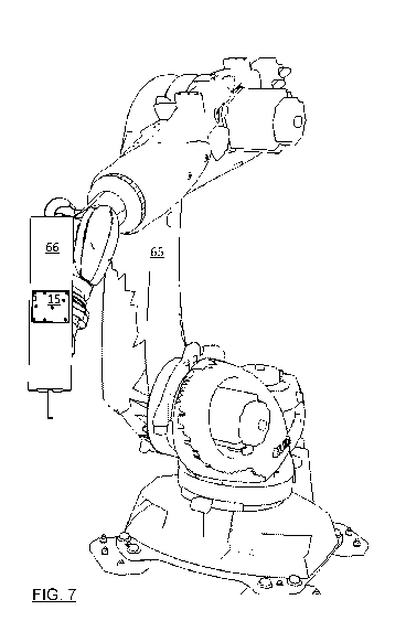
[0070] FIG. 7 is a schematic illustration of a robot 65 having an end
effector 66 onto
which is mounted a MTP 15. It will be appreciated that placement of a MTP on a
robot is
a sensitive choice. To avoid adding any further constraints to mobility of the
robot, the
MTP is mounted to the robot within its working envelope. It is expected that
locations
near a wrist of the robot and along links of the robot may be ideal locations
for mounting
the MTP. A trade-off in separation S of the ICs may be required to avoid
enlarging the
robot envelope, or the robot envelope may be extended. If the separation S is
made
smaller, it reduces a set of positions and orientations over which the ROMS
can image
and determine with required accuracy a distance to, the MT(s). It will be
noted that
CA 03092187 2020-08-25
WO 2019/162732 PCT/IB2018/051197
mounting the MTP to an end effector may be a good choice because a size of the
end
effector may be relatively large, and frequently is presented for view,
compared with a
wrist of the robot, although other joints may be regularly in view as well.
[0071] An advantage of placing the MTP on a robot is that the recalibration
of the 3D-
IS is performed in the vicinity of the locus of action, which is presumably
where calibration
would be most critical. The ROMS may rarely operate over certain parts of the
FoV of the
3D-IS, which may be acceptable, especially if the robot is in an extreme pose
at that part
of the FoV and little critical activity occurs within that range of the FoV.
[0072] While the MTP is shown particularly as mounted to robot 65 for
situated,
opportunistic recalibration, it could equally have been mounted to a gantry-
style machine,
or other moving, mobile, or stationary tools or equipment within the FoV, such
as
vehicles, trucks, carts, etc. as well as workers.
[0073] FIG. 8 is a schematic illustration of a time overlapped image of a
calibration
process, showing how calibration points can be taken at a number of points
within a 3D-
IS's FoV 60. The FoV 60 is shown as a pyramidal frustum as is naturally
defined by a
solid angle of the 3D-IS (view pyramid), bounded by front (61) and rear (62)
planes (or
spheres centered on the origin) that define the bounds within which the 3D-IS
operates.
Three checker-board style MTs 10B are shown for reference, and 13 instances of
the
MTP 15 (of FIG. 2) are shown distributed within the FoV 60.
[0074] It will be noted that highest uncertainties of the 3D-IS may be at a
greatest
distance from an origin of the 3D-IS in the FoV (along the rear plane or
sphere 62), or in
two bands respectively along the rear plane or sphere 62 and along the front
plane or
sphere 61. While FIG. 7 shows a same MTP 15 used throughout, two different
MTPs
having ROMS with different respective separations S of ICs can be used. For
example, a
MTP with a smaller S can be used for a proximal range of FoV depths within
which an
accuracy of the position is satisfactory, and a second MTP with a larger S can
be used for
a distal range of depths. Preferably the two ranges of depths overlap.
EXAMPLE
[0075] The present invention has been demonstrated using a structured light
3D-IS
(SLS) (FoV of -8 m3 = 2mx2mx2m) as shown in FIG. 9A. The structured light SLS
includes a stand, a special purpose projector with optics as taught in
Applicant's patent
US 8,754,954, a camera, and a computer for collecting data and applying a
deconvolution
21
CA 03092187 2020-08-25
WO 2019/162732 PCT/IB2018/051197
process as explained in Applicant's patent US 8,411,995. The MTP has also been
used
to calibrate.
[0076] FIG. 9A also shows a series of MTs in the form of standard
photogrammetric
markers. The markers were applied as photogrammetric stickers (Synthetic
paper:
Mactac metro label white perm; the dots are 1 cm diameter, and surrounded by
black ink
printed by Spicers Canada ULC on commercial printer) that were mounted to
respective
steel plates. The stickers are black with white circular targets having a high
absorbance
contrast to define the target. The minimum number of sticker is three,
typically we use 24
markers. The 24 targets were provided on 3 separate plates having 8 targets
each. The
stickers were applied by hand and did not have a prescribed arrangement on the
plate,
although they were generally spaced by about 5 cm from the 2 or 3 nearest
dots. Two
steel plates are horizontally arranged, the right most steel plate being
separated from the
other horizontal steel plate by 40 cm vertically upwards and 18 cm left to
right (nearest
corners), and the vertically arranged steel plate is 12 cm behind the
horizontally arranged
steel plates.
[0077] While FIG. 9A shows a MT consisting of a matte white (high
reflectance) on a
black (high absorbance) background, Applicant has found that using
retroreflective
targets allows for a much higher (-2 orders of magnitude) reflectance which
can be
helpful for reducing illumination requirements. While edges of the
retroreflective targets
are not defined as nicely as these sticker-applied markers, the speed of
imaging of the
ROMS camera can be reduced substantially and this improves stability of the
images and
accuracy of measurements.
[0078] FIGs. 9B,C are photographs of a prototype MTP. It is composed of a
calibration plate, a frame with three cameras, and a computer. FIG. 9B shows
the MTP
assembled, and FIG. 9C shows the MTP with the calibration plate disassembled.
The
frame is mounted on a rolling tripod to ease the moving of the self-
positioning target.
Note that the computer could be installed on the frame.
[0079] The three cameras are mounted on the frame with a distance between
the two
cameras on the bottom being 30 inches, and a distance between either bottom
camera
and the top is 25 inches. The focal length distance of the cameras is set to
2.5 m. The
technical operating specifications of the camera are: XIMEATm, model MC124MG-
SY, Bus
type USB 3, 1 monochrome channel, frame rate: 10 fps, dynamic interval: 10
bits, pixel
pitch: 5.5 pm, resolution: 12 M pixels, and aperture: F8. A thermocouple
sensor was
embedded in the camera and used for image correction.
22
CA 03092187 2020-08-25
WO 2019/162732 PCT/IB2018/051197
[0080] Two
different types of calibration plates were tested for fitness. The selection
of the type of target depends mostly on the accuracy and resolution of the SLS
system to
be calibrated. Table 1 provides construction details for two designs. FIGs.
9B,C show
the glass-based calibration plate. It is noted that certain glass, and
monocrystalline
ceramics have lower thermal expansion coefficients, which can be useful, and
high
ceramic content metal matrix composites (such as Applicant's W02014/121384),
or even
thin natural or artificial granite plates, can have good stiffness to weight
ratios, excellent
stability, and reasonable manufacturability.
Table 1
Lower accuracy target Higher accuracy target
Material Glass Machined Stainless steel
or aluminium.
Surface processing Painted Vaper blasted
Circular Fiducial marker Laser hatching or Photog ram metric target
photog ram metric target mounted by press fit.
printed on synthetic paper
and adhered to the surface
Mounting on frame Nuts and bolts mounting Kinematic mounts with
hardware redundant back up
fasteners
Weight 10 pounds 40 pounds
Temperature probe None thermocouple sensor
[0081] The
size of the calibration plate was decided based on many factors. To
reduce a number of images of the MTP required to span a FoV, the calibration
plate
should be as large as possible. However, larger plates with tight tolerances
on the
flatness and fiducial marker positions are far more expensive to build.
Practical concerns
like weight and portability favor smaller plate sizes. In general it is
practical to use plate
sizes that are commensurate with the separation S used (such as 60%-140% S,
more
preferably 75%-120% S), as the rigid structure for supporting the cameras can
also serve
to support and/or protect the plate. The calibration plates were 26 by 26
inches.
[0082] The
frame was designed so that the calibration plate can be detached. In
disassembled form the MTP is conveniently transported or stored. The re-
assembly is
not need to be repeatable). The frame was designed to be sufficiently rigid
such that the
cameras do not move with respect to the calibration plate, or each other, when
the self-
positioning target is moved or subjected to vibration. Stiff,
lightweight, vibration
absorbing, low coefficient of thermal expansion, materials are preferred.
The
photographed frame is made of Aluminum, which is stiff and relatively
lightweight, but
does not have the best CTE. Plans for a lighter and stiffer structure made out
of carbon
fibre reinforced polymer, and for a design resembling FIG. 5, are in the
works.
23
CA 03092187 2020-08-25
WO 2019/162732 PCT/IB2018/051197
[0083] The
controlling hardware is not shown in the drawings, but is essential to
implementation. The controlling hardware included a HP Z-400 workstation,
which
executes many functions. First, it is responsible for the synchronization all
the cameras
of the ROMS. The cameras were USB connected to the controlling hardware via a
USB
device NI-USB-6001 from National Instruments. The USB device generates an
electronic
trigger signal for ROMS camera synchronization. A second function is to send a
signal to
the SLS to prompt acquisition by the SLS, of a 3D image of the FoV. This is
specifically
performed with an Ethernet network connection that is established between the
SLS and
the controlling hardware. In an
industrial setting, a wireless network or infrared
transmission network could alternatively be used. The third function is to
monitor the
movement of the MTP with respect to the SLS while the SLS is acquiring the 3D
image
(this is performed in structured light systems, by a succession of images with
different
illumination patterns in successive time steps). The movement monitoring is
done by
measuring the variation of position of the marker in the image taken by the
ROMS
throughout the 3D image acquisition. As the ROMS takes many images while the
3D
image is being acquired by the SLS, a stability of the MTP throughout the SLS
imaging is
assessed and used to ensure that any errors in the measured positions of the
calibration
plate features are not attributed to the motion of the MTP, as opposed to the
calibration of
the 3D-IS. Accelerometers on-board the MTP could be used to assist this
monitoring. A
fourth function of the controlling hardware is to continuously track the
position of the
photogrammetric markers in the images of the three cameras, and compute the
position
and orientation of the self-positioning target using this position. Finally,
the controlling
hardware reads the temperature probes, assesses the stability of the MTP
throughout the
SLS 3D image acquisition, and determines the position and uncertainty of the
position
and orientation of the calibration plate, to associate an error in the SLS
calibration with
each measurement position.
[0084] The
frame and the calibration plate are expected to be subject to temperature
variation. For this reason, temperature probes may be installed on both the
calibration
plate and the frame when the system is expected to work in an uncontrolled
environment.
For example, air temperature measurements, as well as surface temperature
readings of
the calibration plate and frame, may all be used with a suitable model of the
system to
determine displacements of the cameras, and variations of positioning of the
camera
centres with respect to a centre of the calibration plate. The temperature
information is
communicated to the controlling hardware that applies temperature correction
to the
position and orientation computed by the ROMS.
24
CA 03092187 2020-08-25
WO 2019/162732 PCT/IB2018/051197
CALIBRATION EXAMPLE
[0085] The procedure for calibrating the SLS required first calibration of
the MTP than
it would be for workspace deployment. An initial step was required because the
MTP was
not calibrated itself. This same step would be required any time the MTP
itself may have
been modified since its last calibration. If the MTP is not made for
disassembly, this step
will less frequently be required for deployment on a workspace.
[0086] When commissioning the MTP or recalibrating the MTP, one must
measure
the position of the fiducial marks on the calibration plate; and calibrate the
cameras.
Typically, the calibration plate measurement will be performed using a CMM
with an
imaging system. Typically the work would be done by a recognized laboratory of
metrology, and will provide traceability of the measurements with the MTP.
[0087] This camera calibration step may be performed when the cameras or
frame
are changed or at some regular time interval (once a month) in order to verify
that the
system is stable. The objective of this step is to calibrate the intrinsic
parameters of each
camera and calibrate the rigid transformation between all cameras (orientation
and
position). This calibration was performed using the technique known as planar
calibration
[Z. Zhang, "A flexible new technique for camera calibration", in IEEE
Transactions on
Pattern Analysis and Machine Intelligence, vol. 22, no. 11, pp. 1330-1334, Nov
2000, the
contents of which are incorporated herein by reference]. To perform this
calibration we
use the plate that can be unmounted from the self-positioning target. Note
that the size of
the plate is such that it covers the entire volume in which the cameras can
triangulate
points. Thus the camera ring is designed to work on a volume for which it is
practical to
build an accurate and cost efficient calibration plate. Having a calibration
plate that
covers the entire volume allows a more accurate calibration than using a small
target
(without self-positioning capability) that is moved in the volume. The
calibration of the
camera ring requires many images of the plate at different orientations with
respect to the
camera ring. The temperature of the plate, cameras and frame are recorded
during this
calibration. Once the calibration is performed, the plate is carefully
reinstalled on the
frame and the MTP is ready to be used. Note that the procedure does not assume
that
the plate will always be positioned at the same position when it is remounted
on the
frame.
[0088] With the calibrated MTP, computing a 3D position of the
photogrammetric
markers that are fixed with respect to an origin of the SLS is performed. This
step would
be avoided if the photogrammetric markers (or other metrological target) were
rigidly and
CA 03092187 2020-08-25
WO 2019/162732 PCT/IB2018/051197
reliably mounted to the 3D-IS (SLS) on sale of the system. As this was not the
case for
our test system, photogrammetric markers were installed on the SLS. While 24
targets
were used, our next embodiment will use 40 markers (10 markers on each of 4
plates).
The MTP was brought in front of the SLS. Each of the three cameras of the ROMS
imaged the photogrammetric markers. Relying on the calibration of the ROMS,
the
position of the center of each fiducial marker is computed. Thus, a
reconstruction of the
24 targets in 3D is achieved.
[0089] This 3D reconstruction process can be repeated each time the self-
positioning
target is or may have moved during the SLS calibration step. Since the marker
is placed
on the SLS, and the SLS is a rigid object that does not change form, it is
possible to find
the rigid transformation between each position of the self-positioning target.
This allows
for the computation of the position of the three cameras with respect to the
SLS at each
image acquisition. However, this does not provide us with the position of the
plate since
the rigid transformation between the plate and the cameras is unknown.
[0090] An initial calibration of the SLS was required, for the process to
work. Again
this step would not be performed in a workspace deployment, as the 3D-IS/SLS
would
already be bought with an initial calibration, unless the calibration file
were lost or
destroyed. If a SLS calibration of another SLS of the same model cannot be
obtained, an
initial calibration would have to be recovered. We simply used two images of
the
calibration plate of the MTP and performed a planar calibration with that data
given the
known map of the calibration plate. Note that this is a temporary calibration
that does not
need to be accurate.
[0091] The next step was computing the rigid transformation between the
camera of
the ROMS and the markers on the calibration plate. An artifact is needed for
computing
the rigid transformation between the cameras and the plate. In our experiment,
we used
the artifact shown in FIG. 10. This artifact is composed of 8 spheres. Note
the presence
of a black bracket at the base of each sphere. The bracket can be rotated 360
degrees
around the base of the spheres so that the bracket can be placed behind the
sphere for
any viewing angle of the artifact in the plane, without moving the artifact
itself. As such
the white spheres were provided in front of a black background for imaging by
the MTP or
the SLS, which ever was imaging the artifact. The positions of the spheres on
the artifact
were measured using the ROMS cameras using the triangulation process used to
measure the photogrammetric markers.
26
CA 03092187 2020-08-25
WO 2019/162732 PCT/IB2018/051197
[0092] The artifact is placed between the MTP and the SLS such that the MTP
and
SLS can both image the artifact (with the brackets suitably positioned). The
MTP is then
used to triangulate the position of the photogrammetric markers and the
position of the
artefact in the same reference frame. Using the temporary calibration of the
SLS camera,
we recovered the relative pose of the SLS camera with respect to the artifact.
Knowing
both the pose and the measurement taken by the MTP, we computed the relative
position
and orientation of the SLS camera with respect to the photogrammetric markers
installed
on the SLS. Note that the recovered relative position and orientation of the
SLS camera
with respect to the photogrammetric markers is only used as an initialization
during the
SLS calibration.
[0093] Finally, we calibrated the SLS in two steps: the first was data
acquisition and
required approximately an hour of labor; the second was data processing which
typically
required a few minutes. The data acquisition involved placing the MTP in the
FoV of the
SLS, and the positioning the MTP. Using the orientation and position of the
ROMS
camera with respect to the calibration plate, and the temporarily SLS
calibration, we
predicted the position in the 3D image from the SLS, of the fiducial markers
on the
calibration plate. Standard image processing methods were used to refine this
position.
The MTP was moved while its controlling hardware continuously tracked the
photogrammetric markers. Once the MTP stopped moving (stability was observed),
another acquisition of the SLS camera was performed. For each position of the
MTP, we
extracted the position of the SLS with respect to the target and a list of
correspondences
between the positions of the fiducial markers and their images into the SLS
camera was
produced. This acquisition is repeated multiple times such that the entire
reconstruction
volume of the SLS is covered.
[0094] Once all the data was collected, a non-linear bundle adjustment (see
[Triggs
B., McLauchlan P.F., Hartley R.I., Fitzgibbon A.W. (2000) "Bundle Adjustment ¨
A
Modern Synthesis." In: Triggs B., Zisserman A., Szeliski R. (eds) Vision
Algorithms:
Theory and Practice. IWVA 1999. Lecture Notes in Computer Science, vol 1883.
Springer, Berlin, Heidelberg], the contents of which are incorporated herein
by reference)
was used to improve the calibration the SLS and find the rigid transformation
between the
camera of the SLS and the photogrammetric markers. The exact mathematical
model
minimized depends on the distortions of the optical system of the SLS,
specifically, in the
present SLS, where a large field of view lens (fish-eye camera) substantial
radial
distortions are corrected, as well as some minor tangential distortions (to
correct
deviations from a pin-hole model).
27
CA 03092187 2020-08-25
WO 2019/162732 PCT/IB2018/051197
COMPARASON OF CALIBRATION WITH MTP
[0095] The calibrated SLS was compared with the only other technique that
might be
used in an industrial workspace: calibration with a laser tracker. The laser
tracker costs
about 25 times the cost of the MTP (not counting the time to construct) and
the time it
took to calibrate the SLS was 2-3 days. The laser tracker imaged the marked
surface of
the MTP at a few positions per minute. The frame of the shown MTP was
outfitted with
three nests for spherically mounted retroreflectors, one near each of the
cameras. The
ROMS was deactivated, and the laser tracker data was acquired during the SLS
acquisition of a 3D image.
[0096] Both calibrations were tested using a flat plate and were found to
have the
same mean accuracy. The form errors of the data of planar surfaces scanned by
the SLS
calibrated using both the laser tracker and the self-positioning target, were
similar (about
0.3 mm) and mostly the result of the range uncertainty of the SLS.
[0097] Applicant has demonstrated a very low cost, high accuracy
calibration system
for 3D-ISs.
[0098] Other advantages that are inherent to the structure are obvious to
one skilled
in the art. The embodiments are described herein illustratively and are not
meant to limit
the scope of the invention as claimed. Variations of the foregoing embodiments
will be
evident to a person of ordinary skill and are intended by the inventor to be
encompassed
by the following claims.
28