Note: Descriptions are shown in the official language in which they were submitted.
DISPENSING CONTAINER WITH INTERIOR ACCESS
BACKGROUND OF THE INVENTION
1. Field of the Invention
The present invention relates to a dispensing container. More specifically,
the present
invention relates to a dispensing container that allows its users to access
all of its interior
surfaces.
2. Description of Related Art
Dispensing containers used for solids, gels, pastes, cosmetics, condiments,
all
forms of viscous materials and any non liquid content, typically are small
plastic
containers that include a means for the dispensing of the content within the
said
container. A number of dispensing containers use gravity or applied pressure
from the
user by squeezing the container for the content to disperse from a small
opening usually
in the top of the container. Some of these dispensing containers may include
spray
pump or a hand pump that suctions the content through a straw-type tubing and
then
emits the content into the user's hand, onto the user's food, or on the
surfaces being
cleaned by the user with regard to any soap or cleaning content. The typical
dispensing
container may vary in size but usually contains a few ounces up to 20 or 30
ounces of
fluid within the container for use. The common hand pump utilizes a straw-like
tubing
that extends downwardly into the dispensing container, many times the bottom
surface
of the dispensing container is flat and therefore the pump-type dispenser may
leave
unused content within the dispensing container. Most of the unused content is
unable to
be suctioned through to the tubing due to the positioning of the tube that
extends into
the dispensing container. Many times the tube is extended downward in the
center of
the dispensing container and functions in an efficient manner until a low
level of content
is left within the dispensing container. The interior walls of the dispensing
container is
also left with unused content. It would therefore be advantageous to have a
dispensing
container that permits its users to access all of its interior surfaces once
its normal
dispensing process can no longer disperse its remaining content.
1
Date Recue/Date Received 2022-10-20
CA 03092211 2020-08-25
WO 2020/005311 PCT/US2018/064861
BRIEF SUMMARY OF THE INVENTION
Applicants' invention comprises further improvements in the configuration of
the
finished dispensing container and in the manufacture of the finished
dispensing
container to provide its users access to all of its interior surfaces. The
purpose of a
dispensing container with interior access is for when the said dispensing
container can
no longer disperse the low level content within its bottom surface and
interior walls
through its normal dispensing process.
Applicants' dispensing container with interior access (100) comprises of: a
container
(100), where said container (100) is structured in two halves (1/2), an upper
halve (1)
and a lower halve (2), adjoined by a pivoting hinge (3) to hold the two halves
(1/2)
together with the following combination of locking components on the lower
halve (2) of
the dispensing container with interior access (100); a front lower snap bump
(8), a left
lower snap bump (12), a right lower snap bump (11), and lower radial snap
bumps (5)
that serve as the tongues and the following combination of locking components
on the
upper halve (1) of the dispensing container with interior access (100); a left
upper snap
(4), a front upper snap (6), a right upper snap (10), and an upper radial
snapping rim (9)
that serve as the grooves; and additional locking and unlocking components,
wherein
the additional locking and unlocking components are distributed across the
lower halve
(2) of the dispensing container with interior access (100) comprises of a
front lower
relief indentation (15), a right lower relief indentation (14), a left lower
relief indentation
(13), and a seal (7); wherein the lower relief indentations (13/14/15) allow
fingers to
grab under the upper snaps (4/6/10) for easy separation of the the lower halve
(2) and
upper halve (1) of the dispensing container with interior access (100).
2
CA 03092211 2020-08-25
WO 2020/005311 PCT/US2018/064861
BRIEF DESCRIPTION OF THE SEVERAL VIEWS OF THE DRAWING(S)
The present disclosure, in accordance with one or more embodiments, is
described in detail with reference to the following figures. The drawings are
provided for
purposes of illustration only and merely depict typical or example
embodiments. These
drawings are provided to facilitate the reader's understanding of the
apparatus and
methods and shall not be considered limiting of the breadth, scope, or
applicability of
the invention. It should be noted that for clarity and ease of illustration
these drawings
are not necessarily made to scale.
FIGS. la-c are drawings of a perspective, side, and rear view of a dispensing
container with interior access (100) with two halves (1/2), an upper halve (1)
and a
lower halve (2) in a closed position adjoined through the embodiment of a
pivoting hinge
(3) along with locking components (4/6/10) and unlocking components (13/14/15)
with
an open inner rim mouth (16) and an area for a logo (17) in accordance with
the
embodiment of the present disclosure;
FIGS. 2a-f are drawings of perspective and side views of a dispensing
container
with interior access (100) with two halves (1/2) in an open position in
accordance with
the embodiment of the present disclosure;
FIGS. 3a-e are drawings of side views of a dispensing container with interior
access
(100) in an open and closed position in accordance with an embodiment of the
present
disclosure;
FIGS. 4a-d are drawings of perspective and side views of a dispensing
container
with interior access (100) in a locked position in accordance with an
embodiment of the
present disclosure;
Some of the figures included herein illustrate various embodiments from
different
viewing angles. Although the accompanying descriptive text may refer to such
views as
"side" views, such references are merely descriptive and do not imply or
require that all
embodiments be implemented or used in a particular spatial orientation unless
explicitly
stated otherwise.
The figures are not intended to be exhaustive or to limit the embodiments to
the
precise form disclosed. It should be understood that the various embodiment
can be
practiced with modification and alteration, and that the invention is limited
only by the
claims and the equivalents thereof.
3
CA 03092211 2020-08-25
WO 2020/005311 PCT/US2018/064861
DETAILED DESCRIPTION OF THE INVENTION
The embodiments described herein are exemplary. Descriptions in terms of these
embodiments is provided to allow various features to be portrayed in the
context of an
exemplary application. As will be clear to one of ordinary skill in the art,
the invention
can be implemented in different and alternative embodiments without departing
from the
spirit or scope of the invention.
Unless defined otherwise, all terms used herein have the same meaning as is
commonly understood by one of ordinary skill in the art to which this
invention belongs.
The current dispensing container on the market today lacks the design and
functionality to release and allow complete access to its viscous content.
When the said
dispensing container can no longer disperse its content the consumer is
burdened by
not having full access to the content they purchased and the environment is
burdened
by the possibility of contamination of disposed dispensing containers that may
have
remaining chemical content in them.
When the current markets dispensing container can no longer disperse its
remaining
content for the consumer the consumer does not reap the full benefits of the
said
product. If the consumer chooses to use alternative methods to access the
remaining
content that could not be dispersed such as: warming up, cutting open, or even
placing
the dispensing container in an upside down position for the content to
eventually
surface, the consumer runs the potential risk of direct or indirect harm and
time wasted
without the guarantee of achieving complete access to the said content nor
preserving it
if the dispensing container is cut open.
Another potential risk that the current dispensing container bears is
environmental
contamination. When consumers dispose of their dispensing containers that have
remaining chemical content in the said dispensing container can have a direct
and
indirect effect on the environment at large.
To achieve better usage the present invention relates to a dispensing
container that
improves the performance of a hand pump and squeeze style dispensing
container. The
dispensing container according to the present invention utilizes unique
features within
the interior and exterior of the container to ensure complete access to the
content
through the use of a secured open, close, lock, and seal system within the
dispensing
container.
4
CA 03092211 2020-08-25
WO 2020/005311 PCT/US2018/064861
DETAILED DESCRIPTION OF THE INVENTION
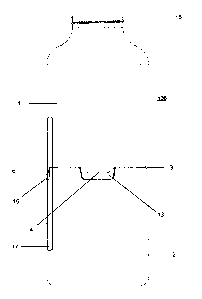
The present invention is a dispensing container with interior access 100 that
includes two halves 1,2, an upper halve 1, a lower halve 2, a pivoting hinge 3
and
locking components 4,5,6,8,9,10,11,12 and unlocking components 13,14,15 that
allows
the dispensing container with interior access 100 to open through the center
of the
upper halve 1 and lower halve 2 of the dispensing container with interior
access 100 for
interior access to any remaining content that its normal dispensing process
could not
disperse through a an open inner rim mouth 16 or dispensing pump.
In addition, there is a seal 7 that will prevent content from seeping once the
upper
halve 1 and the lower halve 2 are adjoined and secured by the pivoting hinge 3
and
locking components 4,5,6,8,9,10,11,12.
FIGS. la-c and FIGS. 2a-f depict dispensing container with interior access 100
in
accordance with the teachings of the present disclosure. Dispensing container
with
interior access 100 comprises of two halves, an upper halve 1 and lower halve
2, with
an incorporated pivoting hinge 3, front lock components comprising of lower
radial snap
bumps 5, a front lower snap bump 8, and a front upper snap 6, with an
unlocking
component comprising of a front lower finger relief indentation 15 opposite of
the
pivoting hinge 3, and multiple snap bumps; a right lower snap bump 11 and a
left lower
snap bump 12, and multiple snaps; a left upper snap 4, a right upper snap 10,
and an
upper snapping rim 9, and multiple indentations; a left lower finger relief
indentation 13
and a right lower finger relief indentation 14, and an integral seal 7 feature
90 degrees
from the pivoting hinge 3 functions in the capacity to assist with opening,
closing,
locking, and unlocking the dispensing container with interior access 100.
In an embodiment a logo 17, symbol, mark, or other design feature may be
placed,
embossed, or molded onto the upper halve 1, lower halve 2 or both halves 1,2
of the
dispensing container with interior access 100 without effecting the opening
and closing
of the dispensing container with interior access 100. Additionally, and/or
alternatively,
either the upper halve 1, lower halve 2 or both halves 1,2 may be covered by a
decorative shell made of metal, plastic, ceramic, or glass.
Dispensing container with interior access 100 may be round, square, octagonal,
triangular or any other geometric shape. It may contain one lock or multiple
locks, one
or multiple pivoting hinges 3, one or more seals 7, It may have one or more
snaps
4,6,9,10, one or more snap bumps 5,8,11,12, and one or more indentations
13,14,15.
CA 03092211 2020-08-25
WO 2020/005311 PCT/US2018/064861
DETAILED DESCRIPTION OF THE INVENTION (Continued)
Dispensing container with interior access 100 may be made from plastic, metal,
ceramic, glass, or any other rigid material. In an embodiment, the upper halve
1 and
lower halve 2 of the dispensing container with interior access 100 may be
disengaged
by lifting the following lock components; the left upper snap 4, the front
upper snap 6,
the right upper snap 10, and the upper radial snapping rim 9 in an upwardly
direction
from the lower radial snap bumps, front lower snap bump 8, right lower snap
bump 11,
and left lower snap bump 12, with the assistance of the left lower finger
relief
indentation 13, right lower finger relief indentation 14, front lower finger
relief indentation
15, and the pivoting hinge 3. In an embodiment multiple snaps 4, 6, 9, 10,
multiple snap
bumps 5,8,11,12 with multiple indentations 13,14,15, along with a pivoting
hinge 3 can
open and close the dispensing container with interior access 100. In another
embodiment multiple snaps 4, 6, 9, 10, multiple snap bumps 5,8,11,12 with
multiple
indentations 13,14,15, along with a pivoting hinge 3 may have specific
locations on the
center body of the dispensing container with interior access 100 and be
sensitive to
pressure and the location on the multiple snaps 4, 6, 9, 10, multiple snap
bumps
5,8,11,12 with multiple indentations 13,14,15, along with the pivoting hinge 3
where
pressure is applied or the amount of pressure applied, i.e, how deep the
multiple snaps
4, 6, 9, 10, multiple snap bumps 5,8,11,12 with multiple indentations
13,14,15, are
pressed, may open the dispensing container with interior access 100. In still
another
embodiment, multiple snaps 4, 6, 9, 10, multiple snap bumps 5,8,11,12 with
multiple
indentations 13,14,15, along with the pivoting hinge 3 may open the dispensing
container with interior access 100 and close the dispensing container with
interior
access 100 by sliding to a first position or a second position. That is, the
multiple snaps
4, 6, 9, 10, multiple snap bumps 5,8,11,12 with multiple indentations
13,14,15, along
with the pivoting hinge 3 may open the dispensing container with interior
access 100 by
sliding rather than lifting. For example and not limitation, the multiple
snaps 4, 6, 9, 10,
multiple snap bumps 5,8,11,12 with multiple indentations 13,14,15, along with
a pivoting
hinge 3 for example could be slid left to unlock and open the dispensing
container with
interior access 100 and right to close and lock the dispensing container with
interior
access 100 or vice versa. In still another embodiment, the multiple snaps 4,
6, 9, 10,
multiple snap bumps 5,8,11,12 with multiple indentations 13,14,15, along with
a pivoting
hinge 3 may be activated by pressing, sliding (up/down or side to side),
rotating, pulling
and/or pushing, twisting or a combination of these multiple snap bumps
5,8,11,12 with
multiple indentations 13,14,15, along with a pivoting hinge 3 for example
could be slid
6
CA 03092211 2020-08-25
WO 2020/005311 PCT/US2018/064861
DETAILED DESCRIPTION OF THE INVENTION (Continued)
left to unlock and open the dispensing container with interior access 100 and
right to
close and lock the dispensing container with interior access 100 or vice
versa.
In still another embodiment, the multiple snaps 4, 6, 9, 10, multiple snap
bumps
5,8,11,12 with multiple indentations 13,14,15, along with a pivoting hinge 3
may be
activated by pressing, sliding (up/down or side to side), rotating, pulling
and/or pushing,
twisting or a combination of these.
FIGS. 3a-e and FIGS. 4a-d depicts dispensing container with interior access
100 in
an unlocked and locked position. Dispensing container with interior access 100
may
have upper halve 1, lower halve 2, multiple snaps 4, 6, 9, 10, multiple snap
bumps
5,8,11,12, multiple indentations 13,14,15, seal 7, and pivoting hinge 3
couples the upper
halve 1 to the lower halve 2 of the dispensing container with interior access
100 and
allows the upper halve 1 to open approximately 90 degrees. Upper halve 1 may
open to
less than approximately 90 degrees or greater than approximately 90 degrees,
such as,
for example, to approximately 95 degrees, approximately 100 degrees,
approximately
105 degrees, approximately 110 degrees, approximately 120 degrees,
approximately
125 degrees, approximately 130 degrees, approximately 135 degrees,
approximately
140 degrees, approximately 145 degrees, approximately 150 degrees, or greater
than
150 degrees.
The upper halve 1 of the dispensing container with interior access 100 remains
in a
closed position until the multiple snaps 4, 6, 9, 10 are lifted upwards from
the multiple
snap bumps 5,8,11,12 through the assistance of the multiple indentations
13,14,15,
along with a pivoting hinge 3. The multiple snaps 4, 6, 9, 10, multiple snap
bumps
5,8,11,12, multiple indentations 13,14,15, may be any standard type of snap
locking
system that engages the multiple snaps 4, 6, 9, 10 with the multiple snap
bumps
5,8,11,12. It may have a inverted lip, raised edge, bevel, tongs, or any other
engagement mechanism to remain engaged with the multiple snaps 4, 6, 9, 10 and
multiple snap bumps 5,8,11,12.
The seal 7 is securely integrated on the top lip of the lower halve 2 of the
dispensing
container with interior access 100 and is configured to be of a sufficient
size, weight,
and thickness to hold the desired viscous content, such that when both the
upper halve
1 and lower halve 2 of the dispensing container with interior access 100 are
adjoined
and secured by the means of multiple snaps 4, 6, 9, 10, multiple snap bumps
5,8,11,12,
and a pivoting hinge 3 the center body of the dispensing container with
interior access
100 will not experience seepage.
7
CA 03092211 2020-08-25
WO 2020/005311 PCT/US2018/064861
DETAILED DESCRIPTION OF THE INVENTION (Continued)
Those skilled in the art will recognize that the present teachings are
amenable to a
variety of modifications and/or enhancements. For example, although the
implementation of various snap components described above may be embodied as
described, they may also be arranged in different embodiments, where for
example, the
multiple snaps 4, 6, 9, 10, multiple snap bumps 5,8,11,12, and multiple
indentations
13,14,15, are arranged in opposite directions, i.e., both facing upwardly or
one up and
one down. Also, with regards to the implementation of the pivoting hinge 3 and
seal 7,
they may be arranged in different embodiments, where for example, the pivoting
hinge 3
may be arranged on the right side or left side of the dispensing container
with interior
access 100 and the seal 7 may be arranged on the upper halve 1, lower halve
inner rim,
or even the affixed to the exterior of the dispensing container with interior
access 100
While the foregoing has described what are considered to be the best mode
and/or
other examples, it is understood that various modifications may be made
therein and
that the subject matter disclosed herein may be implemented in various forms
and
examples, and that the teachings may be applied in numerous applications, only
some
of which have been described herein. It is intended by the following claims to
claim any
and all applications, modifications and variations that fall within the true
scope of the
present teaching.
8
CA 03092211 2020-08-25
WO 2020/005311
PCT/US2018/064861
Patent Citations (13)
Publication Priority date Publication Assignee Title
number date
US3043354A* 1960-07-15 1962-07-10 Edmund J Molded
Fitzgerald plastic
container
US5211302A* 1992-07-16 1993-05-18 Paolo Cosmetic
Tiramani organizer
US5261554A* 1991-05-17 1993-11-16 Forbes Insulated
David G beverage
container
US5503274A* 1994-12-16 1996-04-02 Heidi-Ho Bottle item
Corp.
US5740940A* 1996-06-11 1998-04-21 Weiss; Hinged cover
Dave for an
insulated
beverage
container
US6062412A * 1998-07-30 2000-05-16 Jacobsm Container
eyer, Jr.; cover
Donald
US6155452A * 1998-12-28 2000-12-05 Laurent; Arrangement
Hervej. for resealing
carbonated
beverage
containers
US6223960B1 1997-07-28 2001-05-01 Harley- Motorcycle
Davidson saddlebag
Motor
Company
9
CA 03092211 2020-08-25
WO 2020/005311 PCT/US2018/064861
US6739475B2 1998-04-16 2004-05-25 Nestec Containers
S.A. for articles
of
frozen
confectionery
US7097069B2 2002-07-17 2006-08-29 Cavanag Vendable
h Group prize delivery
Internatio mechanism
nal, Inc. for local
dispensing of
promotional
items
US200801792 2005-03-31 2008-07-31 Forus Multiple
70A1 * Concepts Pivoting Flask
Technolo
gigues
US201201865 2011-01-24 2012-07-26 Dorsey Containment
28A1 * Vernard System for
Brien Animals
U S201403262 2013-05-02 2014-11-06 La Multi-
73A1 * Prairie, compartment
Inc. container
............... ., ..........................................................