Note: Descriptions are shown in the official language in which they were submitted.
1 TWO PIECE TEMPORARY FENCE SUPPORT
2 TECHNICAL FIELD
3 [0001] The following relates generally to physical barriers, and more
specifically, to a two piece
4 temporary fence support.
BACKGROUND
6 [0002] Barriers often are required to be erected quickly or temporarily
for, for example,
7 construction sites, festivals, events, or the like. These barriers can be
used for preventing entry
8 or egress from a particular site, or for directing the flow of crowd
traffic. An example of a
9 conventional barrier is a temporary fencing. Conventional temporary
fencing typically includes a
series of posts interconnected by fence panels. Conventionally, temporary
fencing is free
11 standing, or otherwise self-supporting, without permanent attachment to
the ground.
12 [0003] Conventional temporary fencing panels are supported by a support
having a lateral base
13 for placement along the ground and a vertical component incorporating
one or more posts that
14 support the panels. A vertical component would most commonly have two
posts, each to
support the end of one panel and jointly supporting adjacent ends of two
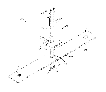
panels. The support is
16 most commonly made from metal, such as steel. In these cases, the
vertical component is
17 generally welded to the base to maximize strength and rigidity.
18 [0004] Due to the nature of the uses of temporary fencing, it is often
the case that fence panels
19 are moved frequently, whether intentionally or not. Unintentional
contact with the panels will
result in a shear force imparted upon the vertical component. Eventually, the
vertical component
21 will become bent or broken.
22 [0005] This problem of continuous breakage through normal wear and tear
is simply accepted
23 in the industry. The common method of repairing a base is by grinding
off the damaged
24 component and then welding on a new vertical component. The cost to
grind and weld a new
component could be approximately $7-10 (as of the date of this writing) if
done by the fence
26 supplier, plus the time, effort, skills and overhead required to do so.
27 [0006] It is therefore an object of the present invention to provide a
fence support in which the
28 above disadvantages are obviated or mitigated and attainment of the
desirable attributes is
29 facilitated.
1
Date Recue/Date Received 2020-08-25
1 SUMMARY
2 [0007] In an aspect, a two piece temporary fence support is provided, the
two piece temporary
3 fence support comprising: a base having an aperture disposed
therethrough; a plate having an
4 aperture disposed therethrough; and a pair of posts extending vertically
from the plate, each
posts permitting a fence panel to be mounted thereon; wherein the base and the
plate are
6 fastenable by a fastener disposed through the aperture of the base and
the aperture of the
7 plate.
8 [0008] In another aspect, a two piece temporary fence support is
provided, the two piece
9 temporary fence support comprising: a base having a pair of apertures
disposed therethrough
proximate the midpoint of the base; a plate having a pair of apertures
disposed therethrough in
11 matching dimension to the base; a pair of posts extending vertically
from the plate, each posts
12 permitting a fence panel to be mounted thereon; and a pair of fasteners
disposed through the
13 apertures of the base and the apertures of the plate to fasten the plate
to the base.
14 [0009] The base and the plate may be made of steel.
[0010] The base and the plate may be coated with an enamel.
16 [0011] The base may be a generally flat plate of metal that is longer
than it is wide.
17 [0012] The base may be symmetrical relative its midpoint.
18 [0013] The base may comprise an aperture formed proximate the end of the
base to permit the
19 base to be fastened to a heavier or immovable structure.
[0014] The base may comprise a pair of apertures and the plate comprises a
pair of apertures
21 matching to those of the base.
22 [0015] The apertures of the plate may be non-circular.
23 [0016] The pair of posts may comprise a first post of square cross-
section and a second post of
24 circular cross-section.
[0017] These and other embodiments are contemplated and described herein.
2
Date Recue/Date Received 2020-08-25
1 BRIEF DESCRIPTION OF THE DRAWINGS
2 [0018] The features of the invention will become more apparent in the
following detailed
3 description in which reference is made to the appended drawings wherein:
4 [0019] FIG. 1 is an exploded perspective view of a two piece temporary
fence support;
[0020] FIG. 2 is a perspective view of an assembled two piece temporary fence
support;
6 [0021] FIG. 3 is a perspective view of an assembled two piece temporary
fence support
7 illustrating the mounting of a pair of fence panels thereto; and
8 [0022] FIG. 4 is a bottom view corresponding to FIG. 3
9 DETAILED DESCRIPTION
[0023] Embodiments will now be described with reference to the figures. For
simplicity and
11 clarity of illustration, where considered appropriate, reference
numerals may be repeated
12 among the Figures to indicate corresponding or analogous elements. In
addition, numerous
13 specific details are set forth in order to provide a thorough
understanding of the embodiments
14 described herein. However, it will be understood by those of ordinary
skill in the art that the
embodiments described herein may be practiced without these specific details.
In other
16 instances, well-known methods, procedures and components have not been
described in detail
17 so as not to obscure the embodiments described herein. Also, the
description is not to be
18 considered as limiting the scope of the embodiments described herein.
19 [0024] Various terms used throughout the present description may be read
and understood as
follows, unless the context indicates otherwise: "or" as used throughout is
inclusive, as though
21 written "and/or"; singular articles and pronouns as used throughout
include their plural forms,
22 and vice versa; similarly, gendered pronouns include their counterpart
pronouns so that
23 pronouns should not be understood as limiting anything described herein
to use,
24 implementation, performance, etc. by a single gender; "exemplary" should
be understood as
"illustrative" or "exemplifying" and not necessarily as "preferred" over other
embodiments.
26 Further definitions for terms may be set out herein; these may apply to
prior and subsequent
27 instances of those terms, as will be understood from a reading of the
present description.
3
Date Recue/Date Received 2020-08-25
1 [0025] The following relates generally to physical barriers, and more
specifically, to a two piece
2 temporary fence support.
3 [0026] Referring first to FIG. 1, a fence support (100) in accordance
with the invention is shown.
4 The fence support includes a first piece being a base (102) and a second
piece being a vertical
component (104). Each of the base (102) and the vertical component (104) are
preferably made
6 from a metal and preferably from steel. The base (102) and the vertical
component (104) may,
7 additionally, be coated with an enamel to mitigate wear and tear. The
base (102) as shown is a
8 generally flat plate of metal that extends longitudinally; that is, it is
generally much longer than it
9 is wide. The base (102) is also generally symmetrical relative its
midpoint (106) in the
longitudinal and lateral axes so that it can be rotated 180 without affecting
use. However, these
11 physical features may be altered as long as the base is sufficient to
support fence panels
12 mounted thereon.
13 [0027] Beginning at the midpoint (106), disposed a short distance
therefrom is a first aperture
14 (108) preferably midway along the lateral axis of the base (102). In an
alternative embodiment,
a single aperture may be provided along the base (102) which preferably, but
not necessarily,
16 could be located at the midpoint of the base or a short distance
therefrom. The apertures (108)
17 may be circular but are preferably a non-circular shape and are designed
to mate with a non-
18 circular portion of a fastener to prevent relative motion between the
fastener and the apertures
19 (108), for reasons to be described later. The non-circular shape shown
in the drawing is square
but could be another suitable polygon shape such as hexagonal, octagonal, etc.
21 [0028] The base (106) is then generally solid. Optionally, an elliptical
aperture (110) may be
22 formed proximate the end of the base (102), again preferably midway
along the lateral axis of
23 the base (102). The elliptical apertures (110) permit the base to be
fastened to a heavier or
24 immovable structure (not shown), such as a concrete weight or the earth.
Fastening in this
manner could be accomplished by a fastener (not shown) such as a screw, nail,
stake, or bolt,
26 for example.
27 [0029] The vertical component (104) comprises a plate (112) from which
two vertical posts
28 (114, 116) arise. The plate (112) as shown is approximately square and
comprises two
29 apertures (118) that are matching to those of the base; that is, they
are identically spaced apart
as the apertures (108) of the base (102). These apertures (118) may be
circular or any other
31 shape permitting the fastener to penetrate therethrough. As with the
base (102) there could be
4
Date Recue/Date Received 2020-08-25
1 only one, or more than two apertures (118). Two or more such apertures
provides benefits such
2 as prevention of rotation between the plate (112) and the base (102).
3 [0030] Furthermore, the plate (112) may comprise just a single post (114,
116) arising
4 therefrom. This may be beneficial for use of a terminal post at the end
of a modular fence panel
installation. In such cases, it is preferred that post (116) is used as
opposed to post (114) for
6 increased stability. Additionally, it is possible that more than two
posts (114, 116) could be
7 provided to facilitate more complex structures.
8 [0031] The plate (112) can then be fastened to the base (102) by use of a
fastener. The
9 fastener illustrated comprises two sets of bolts (120), washers (122) and
nuts (124). In this
manner, fasteners not only replace the weld of the prior art solution but
permit much simpler
11 replacement of broken or damaged vertical components (104). The use of
two fasteners also
12 prevents relative rotation of the plate (112) and the base (102).
13 [0032] As previously mentioned, the bolts (120) preferably comprise a
non-circular portion
14 along their length which is selected to mate with apertures (108) to
prevent relative rotation
therebetween. This permits a person to tighten nuts (124) without having to
manually
16 hold/secure the bolts on the bottom of the base (102) as the base (102)
performs such function
17 for them.
18 [0033] FIG. 2 illustrates the assembled support.
19 [0034] Referring now to FIG. 3 and FIG. 4, vertical posts (114, 116) may
take any cross-
sectional shape that permits supporting a corresponding fence panel (300,
302). Without limiting
21 the invention, such panels may have square vertical posts (304) with a
hollow interior. Vertical
22 post (116) in this case is preferably also square in cross-section and
closely fits within the
23 hollow interior to prevent relative rotation between the vertical post
(116) and the panel. The
24 panels are generally mounted upon the posts and held in place by a
combination of gravity,
mass and friction fit.
26 [0035] Vertical post (114) can then also be square in cross-sectional
shape. However, as such
27 a shape would permit adjacent fence panels to only be disposed in
colinear or perpendicular
28 arrangement, vertical post (114) is preferably circular so that one
panel supported by vertical
29 post (116) is held rigidly in place while adjacent panel supported by
vertical post (114) may be
rotated to a desired angle.
5
Date Recue/Date Received 2020-08-25
1 [0036] While vertical posts (114, 116) could both be circular in cross-
section, this is not a
2 preferred arrangement as relative rotation with both panels can result in
the entire base being
3 rotated so that it is no longer perpendicular to the panels, thus
reducing stability.
4 [0037] Applicant recognized the intended advantages of the embodiments
described herein; for
example, the ability to more easily and cheaply repair damaged fence supports
and the
6 prevention of damage to the vertical supports. A replacement part for the
foregoing
7 embodiments may be approximately 25% (approximately $2.50) of the repair
cost of prior
8 solutions. Thus, Applicant's novel support is much more cost effective
and solves the
9 aforementioned problem by allowing for a quick change.
[0038] Although the invention has been described with reference to certain
specific
11 embodiments, various modifications thereof will be apparent to those
skilled in the art without
12 departing from the spirit and scope of the invention as outlined in the
claims appended hereto.
13 The entire disclosures of all references recited above are incorporated
herein by reference.
6
Date Recue/Date Received 2020-08-25