Note: Descriptions are shown in the official language in which they were submitted.
CA 03092617 2020-08-31
Docket No. PMHA-17107-PCT: FINAL
1
DESCRIPTION
CO2 RECOVERY SYSTEM AND METHOD OF RECOVERING CO2
Field
[0001] The present invention relates to a CO2 recovery
system and a method of recovering CO2 which are capable of
efficiently using water within a system.
Background
[0002] In recent years, as one of the causes of a global
warming phenomenon, a greenhouse effect caused by CO2 has
been pointed out, and there has been an urgent need,
internationally as well, to take measures to protect the
global environment. The generation source of CO2 extends
over all fields of human activities that burn fossil fuel
13 and the demand tor its emission reduction tends to be
further intensified. Along with this, for power generation
facilities such as thermal power plants that use a large
amount of fossil fuel, a way of removing and recovering CO2
of flue gas by bringing the flue gas of a boiler into
contact with, for example, amine-based CO2 absorbent, and a
way of storing the recovered CO2 without releasing it to
the atmosphere have been actively studied.
[0003] As a method of removing and recovering CO2 from
the flue gas by using CO2 absorbent, there is employed a
CO2 recovery system that brings the flue gas into contact
with the CO2 absorbent in an absorber, heats up in a
regenerator the absorbent that has absorbed CO2 to separate
CO2 and regenerate the absorbent, and circulates the
regenerated absorbent in the absorber again for reusing.
[0004] In this CO2 recovery system, in terms of
maintaining the water balance of the absorbent within the
system, it is desired that the supply of water from the
outside of the system be suppressed to a minimum, by using
Date Recue/Date Received 2020-08-31
CA 03092617 2020-08-31
87066936
2
water generated within the system as much as possible. Thus,
it is conceived that a regenerator reflux device is installed
to condense, as reflux water, water contained in emission gas
with which CO2 discharged from the regenerator is entrained,
and the reflux water is circulated and reused with, for
example, a reclaiming device (Patent Literature 1: Japanese
Patent Application Laid-open No. 2012-166139).
Citation List
Patent Literature
[0005] Patent Literature 1: Japanese Patent Application
Laid-open No. 2012-166139
Summary
Technical Problem
[0006] However, according to the conception in Patent
Literature 1, because the reflux water includes a slight amount
of absorption component, it is not possible to efficiently
recover the absorption component in the operation of
reclaiming. In addition, the measures taken at non-stationary
time when the carry-over from the regenerator occurs in some
operating conditions are not sufficient.
[0007] Furthermore, it is desired that compressor condensate
water generated in compressing CO2 in the flue gas discharged
from the regenerator be effectively used.
Date Recue/Date Received 2020-08-31
CA 03092617 2020-08-31
87066936
3
Solution to Problem
[0008]
According to a first aspect of the present invention,
a CO2 recovery system comprising: a CO2 absorber that:
transports flue gas comprising CO2 into contact with a CO2
absorbent to remove CO2 from the flue gas, and discharges a
rich solution that has absorbed the CO2; an absorbent
regenerator that separates the CO2 from the rich solution to
regenerate the CO2 absorbent as a lean solution; a gas
discharge line where a CO2 entrained gas, discharged from a top
portion of the absorbent regenerator, is discharged; a reflux
water drum, disposed in the gas discharge line, that produces
reflux water by separating the CO2 and water from the CO2
entrained gas; a separation-gas discharge line where the CO2
gas separated by the reflux water drum is discharged; a
compressor disposed in the separation-gas discharge line that
compresses the separated CO2 gas; a condensate water drum,
disposed in the separation-gas discharge line, that produces
compressor condensate water by separating the water from the
compressed CO2 gas; a compressor-condensate water line,
connected to the condensate water drum, that supplies the
compressor condensate water as in-system supply water or out-
of-system supply water; and a reclaiming device that
regenerates the CO2 absorbent, wherein: the reclaiming device
Date Recue/Date Received 2020-08-31
CA 03092617 2020-08-31
87066936
3a
is connected to an end portion of the compressor-condensate
water line and includes: a branch line that draws a part of the
lean solution as lean drawn liquid, a reclaimer that takes in
and reserves the lean drawn liquid, an alkaline-agent supply
unit that supplies an alkaline agent into the reclaimer via an
alkaline supply line, a reflux-water supply line that supplies
the reflux water into the reclaimer, a recovery-steam discharge
line that supplies recovery steam discharged from the reclaimer
to a bottom portion side of the absorbent regenerator, and a
heating unit that heats an inside of the reclaimer.
[0009] According to a second aspect of the present
invention, a method of circulating and reusing, with a CO2
absorber, a CO2 absorbent with the CO2 removed by an absorbent
regenerator, the CO2 absorber brings flue gas comprising the
CO2 into contact with the CO2 absorbent to remove the CO2 and
discharges a rich solution that has absorbed the CO2, the
absorbent regenerator separates the CO2 from the rich solution
to regenerate the CO2 absorbent as a lean solution, the method
comprising: separating, by a reflux water drum, the CO2 and
water from a CO2 entrained gas discharged from a top portion of
the absorbent regenerator to produce reflux water; compressing
the CO2 separated by the reflux water drum; separating water
from the compressed CO2 gas to form compressor condensate
Date Recue/Date Received 2020-08-31
CA 03092617 2020-08-31
87066936
3b
water; and conducting a reclaimer operation of the CO2
absorbent by using the reflux water and the compressor
condensate water in a reclaiming device, wherein the compressor
condensate water is used as in-system supply water or out-of-
system supply water, and conducting the reclaimer operation
includes: after regenerating the CO2 absorbent is completed, an
early-stage recovery operation that stops supplying a lean
drawn liquid that is a part of the lean solution into the
reclaiming device, and that recovers a CO2 absorption component
constituting the CO2 absorbent, and a late-stage recovery
operation that stops supplying the reflux water into the
reclaiming device, and that performs finishing recovery of the
CO2 absorption component constituting the CO, absorbent using
the compressor condensate water.
Advantageous Effects of Invention
[0010]
According to the present invention, it is possible to
effectively use, within a system and outside the system,
compressor condensate water for which the water
Date Recue/Date Received 2020-08-31
CA 03092617 2020-08-31
Docket No. PMHA-17107-PCT: FINAL
4
contained in compressed CO2 that was generated in
recovering CO2 is condensed.
Brief Description of Drawings
[0011] FIG. 1 is a schematic diagram illustrating a
configuration of a CO2 recovery system according to a first
embodiment.
FIG. 2 is a schematic diagram illustrating another
configuration of the CO2 recovery system in the first
embodiment.
FIG. 3 is a schematic diagram illustrating still
another configuration of the CO2 recovery system in the
first embodiment.
FIG. 4 is a schematic diagram illustrating still
another configuration of the CO2 recovery system in the
13 first embodiment.
FIG. 5 is a schematic diagram illustrating still
another configuration of the CO2 recovery system in the
first embodiment.
FIG. 6 is a diagram illustrating a relation between
the operating hours (h) of absorption-agent recovery
operation and the absorption agent concentration (wt%) of
residual water in a reclaimer in the first embodiment.
FIG. 7 is a schematic diagram illustrating a
configuration of a CO2 recovery system according to a
second embodiment.
FIG. 8 is a schematic diagram illustrating a
configuration of a CO2 recovery system according to a third
embodiment.
Description of Embodiments
[0012] The following describes the present invention in
detail with reference to the accompanying drawings. The
present invention, however, is not intended to be limited
by the following exemplary embodiments of the invention.
Date Recue/Date Received 2020-08-31
CA 03092617 2020-08-31
Docket No. PMHA-17107-PCT: FINAL
The constituent elements in the following embodiments
include those that are easily assumed by a person skilled
in the art, that are substantially identical, and that are
within a scope of what is called equivalents. Moreover,
5 the constituent elements disclosed in the following
embodiments can be combined as appropriate.
[0013] The embodiments of the invention can effectively
use, within a system and outside the system, compressor
condensate water for which the water contained in
compressed CO2 that was generated in recovering CO2 is
condensed.
When this compressor condensate water is used as
reclaiming water in an absorbent regeneration (reclaimer)
process within the system, because the CO2 absorbent
13 component is hardly contained in the compressor condensate
water, the recovery efficiency of the CO2 absorbent
component in a reclaiming residue in the reclaimer process
is improved. When the compressor condensate water is used
in pump equipment within the system, it can be suitably
used as pump seal water because of no impurities.
[0014] When the condenser compressed water is discharged
and used outside the system, the reduction in the amount of
emissions of entrained absorbent (entrained amine solution)
entrained in emission gas discharged from a CO2 absorber to
the outside can be achieved, by lowering the discharging
temperature of the emission gas for which CO2 discharged
from a top of the absorber has been removed and by
retaining the water balance within the system.
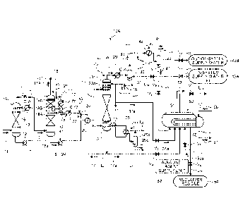
[0015] First Embodiment
FIG. 1 is a schematic diagram illustrating a
configuration of a CO2 recovery system according to a first
embodiment.
As illustrated in FIG. 1, a CO2 recovery system 10A in
Date Recue/Date Received 2020-08-31
CA 03092617 2020-08-31
Docket No. PMHA-17107-PCT: FINAL
6
the first embodiment includes a flue gas cooling tower
(hereinafter also referred to as "cooling tower") 16 that
cools flue gas 11 containing CO2 discharged from, for
example, a boiler, a gas turbine, and the like by cooling
water 15, a CO2 absorber (hereinafter also referred to as
"absorber") 18 including a CO2 recovery unit 18A that
removes CO2 from the flue gas 11 by bringing the flue gas
11 containing the cooled CO2 into contact with a CO2
absorbent (hereinafter also referred to as "absorbent") 17
that absorbs CO2, and an absorbent regenerator (hereinafter
also referred to as "regenerator") 20 that regenerates the
CO2 absorbent 17 by releasing CO2 from a CO2 absorbent 19
that has absorbed CO2 (hereinafter also referred to as
"rich solution"). Then, in this CO2 recovery system 10A,
13 the regenerated absorbent (hereinatter also reterred to as
"lean solution") 17 for which CO2 has been removed by the
absorbent regenerator 20 is sent to the CO2 absorber 18 and
is circulated and reused as the CO2 absorbent.
[0016] The cooling tower 16 is disposed on a gas supply
line Li to which the flue gas 11 is supplied, and the
cooling water 15 is circulated by a pump 12 disposed on a
cooling-water circulation line L9. Then, after being
cooled by a cooler 13 that is disposed on the cooling-water
circulation line L9, the cooling water 15 is supplied into
the cooling tower 16 and cools the supplied flue gas 11
down to a certain temperature.
[0017] The absorber 18 includes the CO2 recovery unit
18A and a washing unit 18B. The CO2 recovery unit 18A
removes CO2 in the flue gas 11 by the CO2 absorbent 17.
The flue gas 11 for which CO2 has been removed is cleaned
with washing liquid 21 in the washing unit 18B placed on
the upper side on the downstream side of gas flow of the
CO2 recovery unit 18A. In the washing unit 18B, the
Date Recue/Date Received 2020-08-31
CA 03092617 2020-08-31
Docket No. PMHA-17107-PCT: FINAL
7
washing water 21 is circulated by a pump 36 disposed on a
washing-water circulation line 1,7. Then, after being
cooled by a cooler 37 that is disposed on the washing-water
circulation line L7, the washing water 21 is supplied into
the washing unit 18B and washes the flue gas 11 that goes
through and for which CO2 has been removed while cooling it
down to a certain temperature. At this time, the CO2
absorbent entrained in the flue gas 11 is washed with the
washing liquid 21 and the CO2 absorbent entrained in
emission gas 11A discharged to the outside is prevented
from discharging, thereby achieving the reduction in
emissions. The temperature of cooling the flue gas 11 is
substantially identical to the supply temperature of the
flue gas 11 in supplying it into the absorber 18, thereby
lb maintaining the water balance within the system. For
example, when the water content in the flue gas 11 that is
supplied into the absorber 18 is 10 wt%, the cooling
temperature is adjusted such that the watcr content of the
emission gas 11A discharged from the top of the absorber 18
is also 10 wt%.
[0018] In the absorber 18 and the regenerator 20, a
rich-solution supply line L3 that discharges the rich
solution 19 from a bottom portion 18a of the absorber 18
and supplies the rich solution 19 toward the regenerator 20
side and a lean-solution supply line L4 that discharges the
lean solution 17 from a bottom portion 20b of the
regenerator 20 and supplies it toward the absorber 18 side
are connected intersecting with each other. At the
intersection of the rich-solution supply line L3 and the
lean-solution supply line L4, a rich/lean-solution heat
exchanger 25 is disposed. In this rich/lean-solution heat
exchanger 25, the rich solution 19 is heated by the lean
solution 17 that is regenerated in the regenerator 20, and
Date Recue/Date Received 2020-08-31
87066936
8
is supplied to the absorbent regenerator 20. Between the
rich/lean-solution heat exchanger 25 and the absorber 18, a
lean solution pump 32 that raises the pressure of the lean
solution 17 and a lean solution cooler 33 that cools the
lean solution 17 by cooling water (C.W) are disposed, and
after being raised in pressure and cooled, the lean
solution 17 is supplied into the CO2 absorber 18.
[0019] On the bottom portion 20b side of the regenerator
20, a reboiler 26 disposed on a reboiler line L5 is
provided. In this reboiler 26, in circulating a part of
the lean solution 17 in the reboiler line L5, it is
indirectly heated by saturated water vapor 26a and the water
vapor is supplied to the inside of the regenerator 20. In
the reboiler 26, a saturated-water vapor supply line L6
that supplies the saturated water vapor 26a is provided.
On this saturated-water vapor supply line L6, a separation
drum 26b is disposed that separates vapor condensate water
26c.
[0020] As for the CO2 recovery system 10A, there are a
case in which it is retrofitted in order to recover CO2
from an existing flue gas source and a case in which it is
placed along a newly equipped flue gas source at the same
time. In the line of the flue gas 11, an openable and
closeable dumper is installed, and is opened when the CO2
recovery system 10A is in operation.
[0021] In the method of recovering CO2 using this CO2
recovery system 10A, first of all, the flue gas 11
containing CO2 from a boiler, a gas turbine, and the like,
for example, is sent to a flue gas cooling device 16 after
having raised the pressure by a flue gas blower (not
depicted), and is cooled therein by the cooling water 15
and sent to the CO2 absorber 18.
[0022] In the CO2 absorber 18, the flue gas 11 makes
Date recue / Date received 2021-12-15
CA 03092617 2020-08-31
Docket No. PMHA-17107-PCT: FINAL
9
countercurrent contact with the CO2 absorbent 17 using an
amine-based absorption agent, for example. Then, the CO2
in the flue gas 11 is absorbed in the CO2 absorbent 17 by
chemical reaction. The CO2-removed flue gas after having
removed the CO2 in the CO2 recovery unit 18A makes gas-
liquid contact with the circulating washing water 21
containing the CO2 absorbent supplied from a nozzle in the
water washing unit 18B in the CO2 absorber 18, and the CO2
absorbent 17 entrained in the CO2-removed flue gas is
recovered. Furthermore, the emission gas 11A for which the
CO2 has been removed is released outside the system by a
gas discharge line L2 connected to the top portion. The
rich solution 19 that has absorbed CO2 is raised in
pressure by a rich solution pump 24 and, at the rich/lean-
13 solution heat exchanger 23, is heated by the lean solution
17 that was regenerated by the absorbent regenerator 20
(the other of the lean solution 17 is cooled by the heat
exchange) and is supplied to the absorbent regenerator 20.
[0023] The rich solution 19 released to the inside from
a lateral upper portion 20a side of the absorbent
regenerator 20 causes an endothermic reaction by the water
vapor supplied from the bottom portion 20b side, thereby
desorbing and releasing most of CO2. The CO2 absorbent
that released in the absorbent regenerator 20 a part or
most of CO2 is referred to as semi-lean solution. This
semi-lean solution becomes, by the time it reaches the
bottom portion 20b of the absorbent regenerator 20, the
lean solution 17 for which almost all CO2 has been removed.
As for this lean solution 17, a part thereof is heated up
by the saturated water vapor 26a in the reboiler 26 and
supplies the water vapor for CO2 desorption to the inside
of the absorbent regenerator 20.
[0024] Meanwhile, in a top portion 20c of the absorbent
Date Recue/Date Received 2020-08-31
CA 03092617 2020-08-31
Docket No. PMHA-17107-PCT: FINAL
regenerator 20, a gas discharge line L21 that discharges CO2
entrained gas 28 entrained in water vapor released from the
rich solution 19 and the semi-lean solution in the
regenerator, is connected. This gas discharge line L21 is
5 provided with a cooler 29 that cools the CO2 entrained gas
28 entrained in water vapor and a reflux water drum 30 that
flashes the CO2 entrained gas 28 after cooling for gas-
liquid separation. Reflux water 31 that has been separated
and refluxed from the CO2 entrained gas 28 entrained in
10 water vapor in the reflux water drum 30 is supplied by a
reflux-water circulation pump 35 disposed on a reflux water
line L23 to the upper portion of the absorbent regenerator
and to the washing water 21 side (*1).
[0025] At the top portion of the reflux water drum 30, a
13 separation-gas discharge line L22 that discharges separated
CO2 gas 40 is connected. This separation-gas discharge
line L22 is provided with a compressor 41 that compresses
the CO2 gas, a cooler 12 that cools the compressed gas, and
a condensate water drum 44 that separates compressor
20 condensate water 43 for which water vapor is condensed by
the compressor 41. CO2 gas 45 that was separated by the
condensate water drum 44 is discharged to the outside of
the system via a gas discharge line L24, is separately
compressed by a compressor, and is recovered. This
recovered CO2 gas 45 is injected into an oilfield by using
enhanced oil recovery (EOR) or is reserved into an aquifer
to achieve measures against global warming, for example.
[0026] A plurality of compressors 41 may be placed, and
in that case, there are multiple compressors 41 and
multiple condensate water drums 44, and a plurality of
drums of compressor condensate water are obtained. In the
following description, in the first embodiment, a case in
which a single compressor 41 and a single condensate water
Date Recue/Date Received 2020-08-31
CA 03092617 2020-08-31
Docket No. PMHA-17107-PCT: FINAL
11
drum 44 are placed will be explained.
[0027] At the bottom portion of the condensate water
drum 44, a compressor-condensate water line L30 that
discharges the compressor condensate water 43 is connected.
To this compressor-condensate water line L30, connected are
a first compressor-condensate water line L31 that supplies
the compressor condensate water 43 as in-system supply
water 43A, a second compressor-condensate water line L32
that supplies the compressor condensate water 43 as out-of-
system supply water 43B, and a third compressor-condensate
water line L33 in which the distal end is connected to a
reclaiming device 50 and that supplies the compressor
condensate water 43 as reclaiming water. Note that, in the
first to third compressor-condensate water lines Ln to L33,
13 first to third on-ott valves Vi to V3, respectively, are
disposed.
[0028] The reclaiming device 50 is, for example, a
pressurized reclaiming device and includes a reclaimer 51
that draws, as lean drawn liquid 17a, a part of the lean
solution 17 to a branch line Lio from the lean-solution
supply line L4 that supplies the lean solution 17
regenerated in the regenerator 20. The reclaimer 51 also
takes in and reserves the lean drawn liquid 17a thus drawn
liquid.
[0029] This reclaimer 51 is provided with an alkaline-
agent supply unit 52 that supplies an alkaline agent 52a to
the inside via an alkaline supply line Lii, a reflux-water
supply line L12 that supplies reflux water 31a inside the
reclaimer 51, the third compressor-condensate water line
L33 that supplies the compressor condensate water 43, a
recovery-steam discharge line L13 that supplies recovery
steam 53 discharged from the reclaimer 51 into the bottom
portion 20b side of the regenerator 20, and a residue
Date Recue/Date Received 2020-08-31
CA 03092617 2020-08-31
Docket No. PMHA-17107-PCT: FINAL
12
discharge line L14 that discharges a reclaimer residue 54.
Note that, in the branch line L10, the alkaline supply line
L11, the reflux-water supply line L12, the recovery-steam
discharge line 1,13, and the residue discharge line 1,141
fourth to eighth on-off valves V4 to Ve, respectively, are
disposed.
[0030] The reclaiming device 50 draws out the lean
solution 17 from a branch portion of the lean-solution
supply line L4 before reaching the rich/lean-solution heat
exchanger 25 from the regenerator 20 via the branch line
Llo as the lean drawn liquid 17a and reserves it inside the
reclaimer 51, heats it in a pressurized condition at high
temperature (for example, 120 to 150 C), and returns the
absorption component, which was vaporized from the lean
drawn liquid 17a, to the bottom portion 20b side of the
regenerator 20 as the recovery steam 53, while discharging
the reclaimer residue 54 that was enriched by heating.
[0031] The L-eclaiminy device 50 mainly includes an
absorbent reservoir and a heating unit. The absorbent
reservoir is configured as the reclaimer 51 of airtight
vessel that reserves the lean drawn liquid 17a_ This
heating unit is provided inside the reclaimer 51, and is
made up of a horizontal U-shaped steam pipe 55, a steam
supply line L15 that is connected to one end of the steam
pipe 55 and that supplies saturated water vapor 56 that is
produced by being heated with a heat source (not depicted)
outside the reclaimer 51, and a condensate-water discharge
line L16 that is connected to the other end of the steam
pipe 55 and discharges steam condensate water 57 to the
outside of the reclaimer 51.
[0032] This reclaiming device 51 opens the fourth on-off
valve V4 and supplies the lean drawn liquid 17a to the
inside of the reclaimer 51, opens the fifth on-off valve V5
Date Recue/Date Received 2020-08-31
CA 03092617 2020-08-31
Docket No. PMHA-17107-PCT: FINAL
13
and supplies the alkaline agent 52a to the inside of the
reclaimer 51 from the alkaline-agent supply unit 52, opens
the third on-off valve V3 and the sixth on-off valve V6 and
supplies supply water (the compressor condensate water 43
and the reflux water 31a) to the inside of the reclaimer
51, and lets the saturated water vapor 56 go through in the
steam line L15. Accordingly, the supplied lean drawn
liquid 17a and the supply water (the compressor condensate
water 43 and the reflux water 31a) are heated to, for
example, 120 to 150 C by heat exchange in a non-contact
manner. Then, deteriorated materials that are non-volatile
materials contained in the lean drawn liquid 17a produce
salt with the alkaline agent 52a to separate the salt from
the absorption component, and are enriched as the reclaimer
residue 54 in the reclaimer 51.
[0033] This reclaimer residue 54 includes liquid
components (liquid components including the absorption
componenL LhaL Was noL recovered, Lhe alkaline ayenL, and
the supply water, and liquid components of non-volatile
materials) in the reclaimer 51, and solid components of
non-volatile components. This reclaimer residue 54 is
discharged to the outside of the reclaimer 51 by opening
the eighth on-off valve Va. The discharged reclaimer
residue 54 is processed by incineration disposal or the
like, for example.
[0034] Meanwhile, the water in the reclaimer 51 (the
lean drawn liquid 17a, the reflux water 31a, and the
compressor condensate water 43) is evaporated by the
heating of the steam pipe 55. At this time, the amine-
based absorbent that was freed by decomposition of the
alkaline agent 52a is vaporized by the heating. The
recovery steam 53 in which this vaporized absorption
component is entrained passes through the opened seventh
Date Recue/Date Received 2020-08-31
CA 03092617 2020-08-31
Docket No. PMHA-17107-PCT: FINAL
14
on-off valve V7 and, through the recovery-steam discharge
line 1,13, is returned to the bottom portion 20b side of the
regenerator 20 (*2). Accordingly, the deteriorated
materials contained in the lean drawn liquid 17a are
separated, and a situation in which the deteriorated
materials are accumulated in the absorbent circulating
inside the system of the recovery system 10 can be
prevented.
[0035] The principle of reclaiming of amine-based
absorbent by using sodium hydroxide as the alkaline agent
will be described. By adding and mixing the alkaline agent
52a such as sodium hydroxide to the lean drawn liquid 17a
containing the absorption component (including amine
nitrate, amine sulfate, and the like) that is fixed by the
13 deteriorated materials and a part ot impurities (including
nitrate salt, hydrosulfate, and the like, for example), and
by heating the mixture, the amine absorption component that
became a free state is recovered together with water as the
recovery steam 53, and the non-volatile materials
(impurities, including sodium nitrate, sodium sulfate, and
the like) are separated and discharged to the outside of
the system as the reclaimer residue (liquid and solid) 54.
[0036] The compressor condensate water 43 that is
separated at the compressor-condensate water line LID from
the condensate water drum 44 is, broadly speaking, divided
into in-system supply water 43A supplied by the first
compressor-condensate water line L31 that is the water used
within the system, and into out-of-system supply water 43B
supplied by the second compressor-condensate water line L32
that is the water used outside the system.
[0037] Mode 1 of Using Compressor Condensate Water
within System
In the following description, in the first embodiment,
Date Recue/Date Received 2020-08-31
CA 03092617 2020-08-31
Docket No. PMHA-17107-PCT: FINAL
a mode in which the compressor condensate water 43 that is
separated at the compressor-condensate water line L30 from
the condensate water drum 44 is used as the in-system
supply water 43A that is the water used within the system
5 will be explained.
As for the water used within the system, it needs to
consider the water balance within the system of the CO2
recovery system 10A. When the in-system supply water 43A
is used, the second on-off valve V2 and the third to ninth
10 on-off valves V3 to Vg are closed. Then, the in-system
supply water 43A is made to connect to the washing-water
circulation line L7 that circulates through the washing
unit 18B of the absorber 18 via the end portion of the
first compressor-condensate water line L31. The in-system
lb supply water 43A and the washing water 21 are then made to
merge so as to increase the percentage of water in the
washing water 21 and decrease the concentration of the
absorption component in the washing water 21.
[0038] When the compressor condensate water 43 is used
as mechanical seal water of various circulation pumps, by
connecting the end portion of the first compressor-
condensate water line Ln to the rich solution pump 24 and
the lean solution pump 32 (*3), it is used as the
mechanical seal water, for the pumps. Accordingly, this
makes it unnecessary to supply the seal water from the
outside. Consequently, this can prevent the absorbent from
being diluted by the water supply from the outside. In
using the reflux water 31 in the pump equipment within the
system, there is a risk of mixture of solid content such as
soot dust when it is in a non-stationary operation
condition in which a failure such as flooding occurs at the
top portion 20c of the regenerator 20. However, because
that risk of the compressor condensate water is low, the
Date Recue/Date Received 2020-08-31
CA 03092617 2020-08-31
Docket No. PMHA-17107-PCT: FINAL
16
reduction in the risk of damaging pump seal can be
achieved.
[0039] Mode 2 of Using Compressor Condensate Water
within System
Incidentally, as the CO2 recovery system is
continuously operated, the impurities in the CO2 absorbent
increases. Thus, it needs to perform CO2 absorbent
component regeneration operation (reclaimer operation) for
removing these deteriorated materials on a regular basis.
This reclaimer operation can be performed in conjunction
with the CO2 recovery operation. When performing this
reclaimer operation, the compressor condensate water 43 is
used as reclaiming water.
[0040] FIGS. 2 to 5 are schematic diagrams illustrating
13 other configurations ot the CO2 recovery system in the
first embodiment. In the following description, with
reference to FIGS. 2 to 5, a case in which the reclaimer
operation is performed will be explained.
[0041] Reclaimer Operation
As illustrated in FIG. 2, when using the in-system
supply water 43A as the reclaiming water of the reclaimer
operation, by closing the first, the second, and the ninth
on-off valves Vi, V2, and Vg and by opening the third on-off
valve V3, the compressor condensate water 43 is supplied
into the reclaimer 51 by the third compressor-condensate
water line L33 as the reclaimer water. By opening the
fourth on-off valve V4 and supplying the lean drawn liquid
17a to the inside of the reclaimer 51, by opening the fifth
on-off valve V5 and supplying the alkaline agent 52a to the
inside of the reclaimer 51 from the alkaline-agent supply
unit 52, by opening the sixth on-off valve V6 and supplying
the reflux water 31a to the inside of the reclaimer 51, and
by letting the saturated water vapor 56 go through in the
Date Recue/Date Received 2020-08-31
CA 03092617 2020-08-31
Docket No. PMHA-17107-PCT: FINAL
17
steam supply line L15, the supplied lean drawn liquid 17a
and the supply water (the compressor condensate water 43
and the reflux water 31a) are heated to, for example, 120
to 150 C by heat exchange in a non-contact manner. Then,
the deteriorated materials that are non-volatile materials
included in the lean drawn liquid 17a produce salt with the
alkaline agent 52a to separate the salt from the absorption
component, and the reclaimer residue 54 is enriched.
[0042] When it is verified that the deteriorated
materials in the CO2 absorbent reached a certain
concentration, by closing the fourth on-off valve V4 of the
branch line Llo and the fifth on-off valve V5 of the
alkaline supply line Lli and by stopping the supply of the
lean drawn liquid 17a and the alkaline agent 52a, the
reclaimer operation is ended.
[0043] Subsequently, a recovery operation that recovers
the CO2 absorption component from the enriched solution of
Lhe reclaimer 51 is performed.
This recovery operation is divided into an early-stage
recovery operation (early stage of recovery) that recovers
the CO2 absorption component that constitutes the CO2
absorbent, and into a late-stage recovery operation (late
stage of recovery) that performs finishing recovery of the
CO2 absorption component that constitutes the CO2
absorbent.
[0044] FIG. 3 illustrates a case of an early stage of
recovery of the recovery operation recovering the CO2
absorption component, and FIG. 4 illustrates a case of a
late stage of recovery of the recovery operation recovering
the CO2 absorption component.
[0045] Early stage of Recovery
In the early stage of recovery, as the supply water to
the reclaimer 51, the reflux water 31a and the compressor
Date Recue/Date Received 2020-08-31
CA 03092617 2020-08-31
Docket No. PMHA-17107-PCT: FINAL
18
condensate water 43 are used.
As illustrated in FIG. 3, when using the supply water
43A as the reclaiming water at the early stage of recovery
of the reclaimer operation, while keeping the first, the
second, the fourth, and the ninth on-off valves Vi, V2, V4,
and V9 closed and keeping the third on-off valve V3 and the
seventh on-off valve V7 open, by supplying the in-system
supply water 43A and the reflux water 31a into the
reclaimer 51 as the compressor condensate water 43, the CO2
absorption component remaining in the residual liquid is
recovered by making it entrained in the recovery steam 53.
[0046] Late Stage of Recovery
In the late stage of recovery, as the supply water to
the reclaimer 51, only the compressor condensate water 43
le is used.
As illustrated in FIG. 4, when using the supply water
as the reclaiming water at the late stage of recovery of
the reclaimer operation, by further closing the sixth on-
off valve V6 from the case of FIG. 3, stopping the supply
of the reflux water 31a, and supplying only the compressor
condensate water 43 into the reclaimer 51, the CO2
absorption component of a very small amount remaining in
the reclaimer residual water is recovered by making it
entrained in the recovery steam 53.
[0047] This is because the CO2 absorption component
remains (remaining amount: several wt%) in the reflux water
31a, and when the CO2 absorption component remains, due to
vapor-liquid equilibrium, the vaporization rate of the CO2
absorption component entrained in the recovery steam 53 is
decreased.
[0048] Thus, in the late stage of recovery, by using the
compressor condensate water 43 for which the remaining CO2
absorption component is of zero or a very small amount and
Date Recue/Date Received 2020-08-31
CA 03092617 2020-08-31
Docket No. PMHA-17107-PCT: FINAL
19
that is compressed by the compressor, further improvement
in the recovery rate can be achieved.
[0049] Reclaimer Residue Discharge
After the recovery of CO2 absorption component is
finished, as illustrated in FIG. 5, by further closing the
third on-off valve V3 from the case of FIG. 4 and stopping
the supply of the compressor condensate water 43 to the
reclaimer 51, and by opening the ninth on-off valve Vg of a
fourth compressor condensate water line L34 and supplying
the compressor condensate water 43 to the reflux water drum
30 as the in-system supply water, the water balance is
retained. Then, by opening the eighth on-off valve Vg of
the residue discharge line L14 and operating a residue
discharge pump (not depicted), the reclaimer residue 54 is
13 discharged to the outside ot the reclaimer 31.
[0050] FIG. 6 is a diagram illustrating the relation
between the operating hours (h) of absorption component
recovery operation and the absorption component
concentration (wt%) of residual water in the reclaimer.
[0051] As illustrated in FIG. 6, at the end time of the
reclaimer operation, when the concentration of the
absorption component is high as xi, the reflux water 31a
and the compressor condensate water 43 are used in
combination as the supply water to the reclaimer 51. At
the latter half of the early stage of recovery, the
recovery efficiency of the absorption component is reduced,
and the curvature of the recovery curve becomes gentle and
reaches a low concentration x2. When it reached this low
concentration x2, by using only the compressor condensate
water 43 as the supply water to the reclaimer 51 and by
further vaporizing the remaining CO2 absorption component,
the improvement in the recovery efficiency of the CO2
absorption component is achieved.
Date Recue/Date Received 2020-08-31
CA 03092617 2020-08-31
Docket No. PMHA-17107-PCT: FINAL
[0052] As a result of this, as compared with a
conventional case in which the reflux water 31a is used as
the reclaiming water to the reclaimer 51, by using the
compressor condensate water 43 for which the mix ratio of
5 the absorption component is zero or very low, the
improvement in the recovery efficiency of the CO2
absorption component can be achieved. Thus, the effective
use of the CO2 absorption component remaining in the
residual water that has conventionally been discharged to
10 the outside of the system as the reclaimer residue 54 and
lost can be achieved.
[0053] Table 1 illustrates one example of an annual
schedule of recovering CO2 in the flue gas by using the CO2
recovery system. However, the present invention is not
13 limited thereto.
[0054] In the present description, the CO2 recovery
system processes the flue gas at all times and is operated
without stopping except for the maintenance and the like.
Although the reclaimer processing depends also on the use
20 frequency and the operating temperature of the CO2
absorbent, it is implemented several times a year, for
example. This implementation is conducted a predetermined
number of times. Alternatively, by analyzing the
concentration of the deteriorated materials of the CO2
absorbent circulating in the circulatory system, if the
result of the analysis exceeds a prescribed value, a part
of the CO2 absorbent circulating in the circulatory system
is drawn out and supplied to the reclaimer and, while the
deteriorated materials are separated and removed from the
CO2 absorbent by adding the alkaline agent to the
reclaimer, the CO2 absorption component is returned to the
circulatory system.
[0055] In the present description, conducting the
Date Recue/Date Received 2020-08-31
CA 03092617 2020-08-31
Docket No. PMHA-17107-PCT: FINAL
21
reclaimer operation twice a year as one example will be
explained. In the annual schedule, for one to four weeks
in June and December, a part of the lean solution 17 is
drawn out to the reclaiming device 50 as the lean drawn
liquid 17a, and the reclaimer operation is conducted.
[0056]
Accordingly, except for this reclaimer operation,
as illustrated in FIG. 1, the compressor condensate water
43 that is the compressor condensate water is used for the
pump seal water as the in-system supply water 43A, for
example. Then, when the reclaimer operation is conducted,
as illustrated in FIGS. 2 to 5, the use as the pump seal
water is stopped and the compressor condensate water 43 is
supplied into the reclaimer 51 as the reclaiming water.
Date Recue/Date Received 2020-08-31
CA 03092617 2020-08-31
DocketNaPMHA-17107-PCT:FINAL
22
[0057]
Table 1
Annual schedule
1 2 3 4 5 6 7 8 9 10 11 12
ON > ON OFF ON > ON OFF
f= (
W
= W
1
H
t:)") OFF > OFF ON OFF > OFF ON
-
- H
= 4--)
r4
[0058] Second Embodiment
FIG. 7 is a schematic diagram illustrating a
configuration of a co, recovery system according to a
second embodiment.
The constituent members identical to those in the
first embodiment are given the identical reference signs
and the redundant descriptions are omitted. As illustrated
in FIG. 7, a CO2 recovery system 10B in the second
embodiment has a flash drum 60 disposed on the third
compressor-condensate water line L33. This flash drum 60
removes the CO2 gas in the compressor condensate water 43,
and it prevents supplying gas components in the reclaimer
operation and improves the recovery efficiency of the CO2
absorption component.
[0059] Third Embodiment
FIG. 8 is a schematic diagram illustrating a
configuration of a CO2 recovery system according to a third
embodiment.
Date Recue/Date Received 2020-08-31
87066936
23
The constituent members identical to those in the
first embodiment are given the identical reference signs
and the redundant descriptions are omitted. As illustrated
in FIG. 8, in a CO2 recovery system 10C in the third
embodiment, placed are, in the CO2 recovery system 10A of
the first embodiment, an inlet thermometer TI that measures
inlet gas temperature (-Li) in the gas supply line Li that
supplies the flue gas 11 into the absorber 18, and an
outlet thermometer T2 that measures the outlet gas
temperature (t2) of the emission gas discharged from a top
portion 18b of the absorber 18.
[0060] In the following description, in the third
embodiment, the mode in which the compressor condensate
water 43 that is separated at the compressor-condensate
water line L30 from the condensate water drum 44 is used as
the out-of-system supply water 43B that is the water used
outside the system will be explained.
[0061] The out-of-system supply water 43B that is used
outside the system is used in utilities of the system and
is, for example, used as the supply water for the water
vapor of the saturated water vapor 26a supplied to the
reboiler 26 and as make-up water of the cooling water used
in the cooling tower.
When it is used outside the system, it needs to make
the amount of discharge smaller than the carried-in amount
of water in the flue gas 11 supplied into the absorber 18.
[0062] In the third embodiment, the outlet gas
temperature (t2) of the emission gas 11A discharged from
the absorber is adjusted to be lower than the inlet gas
temperature (-Li) of the flue gas 11 supplied into the
absorber 18, thereby keeping the water balance. In other
words, because the inside of the system is a closed system,
adjustment is needed for the water discharged to the
Date recue / Date received 2021-12-15
CA 03092617 2020-08-31
Docket No. PMHA-17107-PCT: FINAL
24
outside. Accordingly, when the compressor condensate water
43 is used as the out-of-system supply water 43B, the inlet
thermometer (T1) that measures the temperature of the flue
gas 11 supplied into the absorber 18 and the outlet
thermometer (12) that measures the temperature of the
emission gas 11A discharged from the CO2 absorber are
provided, and the operation is conducted by lowering the
outlet gas temperature (t2) of the emission gas 11A than
the inlet gas temperature (-Li) of the flue gas 11, thereby
making it possible to ensure the water used outside the
system.
[0063] In a bottom liquid-pool portion of the bottom
portion 18a of the absorber 18, a liquid level meter L is
installed, and the liquid level is monitored. Accordingly,
lb the liquid level in the bottom liquid-pool portion can be
properly maintained. As a result, in the CO2 recovery
system, the reduction in the amount of water intake from
the outside can be achieved.
[0064] Table 2 illustrates the comparison between the
case of using the compressor condensate water 43 as the
out-of-system supply water 43B and the case of using it as
the in-system supply water 43A.
[0065] When the compressor condensate water is used as
the out-of-system supply water 43B, the inlet thermometer
(Ti) that measures the temperature of the flue gas 11
supplied into the absorber 18 and the outlet thermometer
(12) that measures the temperature of the emission gas 11A
discharged from the absorber 18 are provided, and the
operation is conducted by lowering the outlet gas
temperature (t2) of the emission gas 11A than the inlet gas
temperature (ti) of the flue gas 11. Accordingly, because
the gas temperature of the emission gas 11A is lowered, the
entrained amount of the CO2 absorbent entrained in the
Date Recue/Date Received 2020-08-31
CA 03092617 2020-08-31
Docket No. PMHA-17107-PCT: FINAL
emission gas 11A is reduced and the reduction in emissions
is achieved.
[0066] As one
example, when the amount of water in the
flue gas 11 supplied into the absorber 18 is 7.3 vol% and
5 the inlet gas temperature (ti) is 40 C, assuming the outlet
gas temperature (t2) of the emission gas 11A discharged
from the top 18b of the absorber 18 is 38 C, the water of
0.8 vol% of the flue gas is to be obtained.
[0067] Meanwhile,
in operating as the in-system supply
10 water 43A so as to retain the water balance, when the
amount of water in the flue gas 11 supplied into the
absorber 18 is 7.3 vol% and the inlet gas temperature (-Li)
is 40 C, the outlet gas temperature (t2) of the emission
gas 11A discharged from the top 18b of the absorber 18 is
15 set to 41 C and is maintained constant so that the water
content of the emission gas 11A on the outlet side becomes
the water content in the flue gas 11 supplied into the
absorber 18. The temperatures and the amounts of water,
however, are examples and the present invention is not
20 limited thereto.
[0068]
Table 2
Out-of-system In-system
supply
supply water 43B water 43A (Washing
(Reboiler steam water, reclaiming
water, etc.) water, etc.)
Absorber inlet 40 C (Water 40 C (Water
gas temperature content: 7.3 vol%) content: 7.3 vol%)
(-Li)
Outlet gas 38 C (Water 41 C (Water
temperature content: 6.5 vol%) content:
7.6 vol%)
(t2)
Water reduction 0.8 vol% -
[0069] As just described, when the compressor condensate
Date Recue/Date Received 2020-08-31
87066936
26
water 43 is used as the out-of-system supply water 43B, the
discharge of the CO2 absorption component entrained in the
emission gas 11A discharged to the outside can be prevented
and the reduction in emissions can be achieved.
[0070] In a case in which the operation to obtain the
out-of-system supply water 43B and the operation of
reclaimer operation are used in combination, as illustrated
in Table 3, in the present description, conducting the
reclaimer operation twice a year as one example will be
explained. In the annual schedule, for one to three weeks
in June and December, a part of the lean solution 17 is
drawn out to the reclaiming device as the lean drawn liquid
17a, and the reclaimer operation is conducted.
Accordingly, except for this reclaimer operation, as
illustrated in FIG. 8, the compressor condensate water 43
that is the compressor condensate water is used as the out-
of-system supply water 43B, for example, as the supply
water for the water vapor of the saturated water vapor 26a
supplied to the reboiler 26 and as the make-up water of the
cooling water used in the cooling tower.
Date recue / Date received 2021-12-15
CA 03092617 2020-08-31
DocketNaPMHA-17107-PCT:FINAL
27
[0071]
Table 3
Annual schedule
1 2 3 4 5 6 7 8 9 10 11 12
ON > ON OFF ON > ON OFF
w
w
(/) 4-)
>ird
o
o,
o
ty, OFF > OFF ON OFF > OFF ON
-H
w
-H
rd 4j
rr
[0072] Then, when the reclaimer operation is conducted,
as illustrated in FIGS. 2 to 5, the use as the pump seal
water is stopped and the compressor condensate water 43 is
supplied into the reclaimer 51 as the reclaiming water.
According to the third embodiment, because it is used as
the out-of-system supply water 43B, the discharge of the
CO2 absorption component entrained in the emission gas 11A
discharged to the outside can be prevented and the
reduction in emissions can be achieved.
[0073] In addition, as the out-of-system supply water
43B, it can also be used, for example, as the substitute of
the make-up water of the utility facilities that are
peripherals, or as a part thereof. At this time, a removal
device such as an ion exchange resin is installed, for
example. As a result, the CO2 absorption component of an
infinitesimal amount included in the compressor condensate
water 43 can be removed.
Date Recue/Date Received 2020-08-31
CA 03092617 2020-08-31
Docket No. PMHA-17107-PCT: FINAL
28
Reference Signs List
[0074]
10A to 10C CO2 recovery system
11 Flue gas containing CO2
16 Flue gas cooling tower
17 CO2 absorbent
18 CO2 absorber
20 Absorbent regenerator
Date Recue/Date Received 2020-08-31