Note: Descriptions are shown in the official language in which they were submitted.
GRATE TRACK WITH CENTER HINGE
TECHNICAL FIELD OF THE DISCLOSURE
This disclosure relates generally to a grate track, and more particularly to a
grate track
having a center hinge.
BACKGROUND
Wheel chocks are objects (e.g., having a wedge, block, or other suitable
shape) placed
against a wheel to prevent it from moving. When vehicles or other large
freight are carried by a
container, a rack, or a deck for long-distance transportation, they typically
need several chocks to
be well-fixed to prevent movement and collision during transport. For
instance, a container may
be outfitted with multiple grate tracks on the floor of the container so that
the chock(s) may be
placed against a tire of the vehicle (or other type of freight) and fixed to
the grate track to constrain
movement of the vehicle or freight during transport.
FIGURES lA and 1B illustrate examples of a chock applied to a grate track.
More
particularly, FIGURE lA illustrates a grate track 102 comprising an outboard
hinge 104 installed
on a rack (e.g., a rack of an auto transport trailer) for transportation.
Outboard hinge 104 may be
fixed to the rack with multiple fasteners and coupled to grate track 102 along
one of its longitudinal
sides to allow grate track 102 to be flipped over (e.g., to allow a user to
clean under the rack or
facilitate removal of snow and ice). In the example of FIGURE 1A, a vehicle is
positioned on the
rack such that a tire 100a of the vehicle is positioned at least partially on
grate track 102. After
the vehicle is positioned on the rack, a chock 106 is placed against tire
100a. Chock 106 is then
affixed to grate track 102. Chock 106 may be affixed to grate track 102 in a
variety of ways. For
example, chock 106 may be affixed to grate track 102 by using teeth to attach
to the track. In some
cases, the teeth may be a set of one or more hooks that engage a wire under
the top layer of the
track. A variety of types of hooks may be used. For example, some hooks may
rotate to encircle
the wire to prevent the wheel chock leaving the track. In some cases, the
teeth may be fixed. Once
affixed to grate track 102, the type of chock illustrated in FIGURE 1A
generates fore, aft, and
cross-car forces. The use of another type of chock, a wheel chock with an
extended lock connected
by a strap over the tire, is described in relation to FIGURE 1B below.
1
Date Recue/Date Received 2020-09-10
FIGURE 1B illustrates another example of a chock applied to a grate track.
Similar to
FIGURE 1A above, FIGURE 1B illustrates a grate track 114 having an outboard
hinge installed
on a rack (not explicitly shown). In the example of FIGURE 1B, a vehicle 100
is positioned on
the rack such that a tire 100b of the vehicle is positioned at least partially
on grate track 114. Chock
108 is placed against tire 100b. In the example of FIGURE 1B, chock 108
comprises an extended
lock 112 connected by a strap 110. To install chock 108, once vehicle 100 is
positioned on grate
track 114, chock 108 is positioned against a side of tire 100b and strap 110
is placed over tire 100b.
Extended lock 112 is then attached to grate track 114 at the other side of
tire 100b. Due to the use
of strap 110 and extended lock 112, when chock 108 is applied to grate track
114, it generates fore,
aft, cross-car, and upward forces.
Existing grate tracks were designed for wheel chocks that have fore, aft, and
cross-car
forces only (e.g., chock 106 described above in relation to FIGURE 1A). When
used with wheel
chocks that have straps over the tires (e.g., chock 108 having extended lock
112 connected to chock
108 by strap 110 described above in relation to FIGURE 1B), existing grate
track designs suffer
from certain deficiencies. For example, wheel chocks used with a strap and
extended lock add an
upward force. The upward force from the strap and chock can cause problems,
such as pulling out
hinge fasteners and raising the ends of the grate track panels where they
adjoin each other. An
outboard hinge (e.g., outboard hinge 104 described above in relation to FIGURE
1A) does not
provide a good anchor for a strap and allows vehicle movement as the grate
track lifts. Thus,
existing grate track designs do not provide a solid anchor for a vehicle or
other large freight during
transportation. Moreover, when the upward force pulls up the ends of the grate
track, the grate
track may cause damage to the underside of the vehicle being transported. In
addition to these
problems, existing grate tracks may be too heavy for a user to lift, which
makes cleaning under
them difficult and can cause problems with removing snow and ice when
necessary. Accordingly,
there is a need for an improved grate track design that alleviates these
problems.
2
Date Recue/Date Received 2020-09-10
SUMMARY
To address the foregoing problems with existing solutions, disclosed is a
railcar system.
The railcar system comprises a railcar and a grate track assembly disposed
longitudinally within
the railcar. The grate track assembly comprises: a first grate; a second
grate; and a center hinge
disposed between the first grate and the second grate. The center hinge is
rotatably coupled to the
first grate along a first longitudinal edge of the center hinge and rotatably
coupled to the second
grate along a second longitudinal edge of the center hinge.
In certain embodiments, a width of the first grate may be different from a
width of the
second grate. In certain embodiments, the width of the first grate may be
eighteen inches. In
certain embodiments, the width of the second grate may be four and one-half
inches. In certain
embodiments, a width of the center hinge may be one and one-half inches.
In certain embodiments, a width of the first grate may be the same as a width
of the second
grate.
In certain embodiments, the first grate may comprise a first gap separating
the first grate
into a first first-grate portion and a second first-grate portion, the first
gap running parallel to a
lateral axis of the first grate. The second grate may comprise a second gap
separating the second
grate into a first second-grate portion and a second second-grate portion, the
second gap running
parallel to a lateral axis of the second grate. In certain embodiments, a
position of the first gap and
a position of the second gap may be staggered with respect to each other
within the grate track
assembly. In certain embodiments, the first first-grate portion and the second
first-grate portion
may be operable to rotate from a first position to a second position. The
first first-grate portion
may be operable to remain in the first position while the second first-grate
portion is in the second
position. The second first-grate portion may be operable to remain in the
first position while the
first first-grate portion is in the second position.
In certain embodiments, the railcar system may further comprise a vehicle
positioned
within the railcar. The vehicle may comprise at least one tire positioned at
least partially on the
grate track assembly. The railcar system may further comprise a chock
positioned over the center
hinge on the grate track assembly and adjacent to the at least one tire. The
chock may comprise
an extended lock connected to the chock by a strap positioned over the at
least one tire. The chock
may be locked to both the first grate and the second grate.
3
Date Recue/Date Received 2020-09-10
In certain embodiments, the center hinge may be affixed to a deck of the
railcar using a
plurality of fasteners. In certain embodiments, the center hinge may comprise
a twin hinge. In
certain embodiments, the first grate may comprise a top wire and a bottom wire
forming a two-
layer grate.
Also disclosed is a grate track assembly. The grate track assembly comprises:
a first grate;
a second grate; and a center hinge disposed between the first grate and the
second grate. The center
hinge is rotatably coupled to the first grate along a first longitudinal edge
of the center hinge and
rotatably coupled to the second grate along a second longitudinal edge of the
center hinge.
In certain embodiments, a width of the first grate may be different from a
width of the
second grate. In certain embodiments, the width of the first grate may be
eighteen inches. In
certain embodiments, the width of the second grate may be four and one-half
inches. In certain
embodiments, a width of the center hinge may be one and one-half inches.
In certain embodiments, a width of the first grate may be the same as a width
of the second
grate.
In certain embodiments, the first grate may comprise a first gap separating
the first grate
into a first first-grate portion and a second first-grate portion, the first
gap running parallel to a
lateral axis of the first grate. The second grate may comprise a second gap
separating the second
grate into a first second-grate portion and a second second-grate portion, the
second gap running
parallel to a lateral axis of the second grate. In certain embodiments, a
position of the first gap and
a position of the second gap may be staggered with respect to each other
within the grate track
assembly. In certain embodiments, the first first-grate portion and the second
first-grate portion
may be operable to rotate from a first position to a second position. The
first first-grate portion
may be operable to remain in the first position while the second first-grate
portion is in the second
position. The second first-grate portion may be operable to remain in the
first position while the
first first-grate portion is in the second position.
In certain embodiments, the center hinge may comprise a twin hinge. In certain
embodiments, the first grate may comprise a top wire and a bottom wire forming
a two-layer grate.
Also disclosed is a method. The method comprises forming a grate track
assembly, the
grate track assembly comprising: a first grate; a second grate; and a center
hinge disposed between
the first grate and the second grate. The center hinge is rotatably coupled to
the first grate along a
first longitudinal edge of the center hinge and rotatably coupled to the
second grate along a second
4
Date Recue/Date Received 2020-09-10
longitudinal edge of the center hinge. The method comprises affixing the grate
track assembly to
a transport vehicle.
In certain embodiments, the method may comprise positioning a vehicle within
the
transport vehicle. The vehicle may comprise at least one tire positioned at
least partially on the
grate track assembly affixed to the transport vehicle. In certain embodiments,
the method may
comprise securing the vehicle to the grate track assembly using a chock
positioned over the center
hinge on the grate track assembly and adjacent to the at least one tire. The
chock may comprise
an extended lock connected to the chock by a strap positioned over the at
least one tire. The chock
may be locked to both the first grate and the second grate.
Certain embodiments disclosed herein may have one or more technical
advantages. For
example, certain embodiments may place the center hinge in line nominally with
an upward force
from a strap. This advantageously results in a stronger grate track with a
center hinge to resist pull
forces from the chock, which may improve the durability of the grate track and
reduce or prevent
damage to the vehicle or other freight due to track lift during
transportation. As another example,
certain embodiments may stagger grate track panel ends, which advantageously
decreases track
dead spots for strap connections. As still another example, certain
embodiments may
advantageously lessen the weight and cost of the grate track by using a center
hinge, which allows
a size of the grate to be reduced. As yet another example, certain embodiments
may provide a
grate track in various sizes to accommodate different needs, such as
transporting a vehicle with
double wheels or a larger deck. Other advantages may be readily apparent to
one having skill in
the art. Certain embodiments may have none, some, or all of the recited
advantages.
BRIEF DESCRIPTION OF THE DRAWINGS
For a more complete understanding of this disclosure, reference is now made to
the
.. following brief description, taken in connection with the accompanying
drawings and detailed
description, wherein like reference numerals represent like parts:
FIGURES lA and 1B illustrate examples of a chock applied to a grate track;
FIGURES 2A and 2B illustrate an example container installed with example grate
tracks;
FIGURE 3 illustrates a top view of an example grate track with a center hinge,
in
accordance with certain embodiments;
5
Date Recue/Date Received 2020-09-10
FIGURES 4A, 4B and 4C illustrate an end view of an example grate track with a
center
hinge, in accordance with certain embodiments; and
FIGURE 5 is a flowchart illustrating an exemplary method, in accordance with
certain
embodiments.
DETAILED DESCRIPTION
As described above, existing grate tracks with outboard hinges were designed
for wheel
chocks that have fore, aft, and cross-car forces only. When used with wheel
chocks that have
straps over the tires, however, existing grate track designs suffer from
certain deficiencies. For
example, wheel chocks used with a strap and extended lock add an upward force.
The upward
force from the strap and chock can cause problems, such as pulling out hinge
fasteners and raising
the ends of the grate track panels where they adjoin each other. An outboard
hinge does not
provide a good anchor for a strap and allows vehicle movement as the grate
track lifts. Thus,
existing grate track designs do not provide a solid anchor for the vehicle or
other freight during
transportation. Moreover, when the upward force pulls up the ends of the grate
track, the grate
track may cause damage to the underside of the vehicle being transported.
Additionally, existing
grate tracks may be too heavy for a user to lift, which makes cleaning under
them difficult and can
cause problems with removing snow and ice when necessary.
The present disclosure contemplates various embodiments that may address these
and other
deficiencies associated with existing grate track designs. In certain
embodiments, this is achieved
through a grate track design having a center hinge. As described in more
detail herein, utilizing a
center hinge enhances the strength of the grate track by providing a sturdier
structure to withstand
pull forces from a chock during transportation. A chock may be applied to the
grate track and
overlap with the center hinge so that an upward pull force caused by the chock
may be eased by
the center hinge. Thus, the center hinge described herein provides a more
effective way to anchor
a vehicle and/or freight in a container. Furthermore, certain embodiments may
prevent damage
to the vehicle and the freight during transportation because of the better
anchor provided by the
grate track disclosed herein.
Several embodiments are elaborated in this disclosure. According to one
example
embodiment, a grate track assembly is disclosed. The grate track assembly
comprises: a first grate;
a second grate; and a center hinge disposed between the first grate and the
second grate. The center
6
Date Recue/Date Received 2020-09-10
hinge may be rotatably coupled to the first grate along a first longitudinal
edge of the center hinge
and may be rotatably coupled to the second grate along a second longitudinal
edge of the center
hinge.
In certain embodiments, the center hinge may comprise a twin hinge. In certain
embodiments, the first grate may comprise a top wire and a bottom wire forming
a two-layer grate.
In certain embodiments, a width of the first grate may be different from a
width of the second
grate. In certain embodiments, the width of the first grate may be eighteen
inches. In certain
embodiments, the width of the second grate may be four and one-half inches. In
certain
embodiments, a width of the center hinge may be one and one-half inches.
In certain embodiments, a width of the first grate may be the same as a width
of the second
grate.
In certain embodiments, the first grate may comprise a first gap separating
the first grate
into a first first-grate portion and a second first-grate portion, the first
gap running parallel to a
lateral axis of the first grate. The second grate may comprise a second gap
separating the second
grate into a first second-grate portion and a second second-grate portion, the
second gap running
parallel to a lateral axis of the second grate. In certain embodiments, a
position of the first gap and
a position of the second gap may be staggered with respect to each other
within the grate track
assembly. In certain embodiments, the first first-grate portion and the second
first-grate portion
may be operable to rotate from a first position to a second position. The
first first-grate portion
may be operable to remain in the first position while the second first-grate
portion is in the second
position. The second first-grate portion may be operable to remain in the
first position while the
first first-grate portion is in the second position.
In certain embodiments, a new hinge may be applied to an existing hinge to
widen the grate
track for dual rear wheel vehicles and/or extra wide track vehicles. For
example, in certain
embodiments a width of the center hinge may be one and one-half inches from a
center line of a
first longitudinal edge to a center line of a second longitudinal edge and may
be a twin hinge. In
certain embodiments, separate hinges may be used with the same distance
between centerlines of
the longitudinal edges of one and one-half inches. In either case, the
resulting one and one-half
inch spacing may advantageously mimic the grate spacing.
According to another example embodiment, a grate track comprises at least one
grate and
a hinge, wherein a total width of the at least one grate is at least 12
inches, and the hinge is rotatably
7
Date Recue/Date Received 2020-09-10
coupled to a longitudinal side of the at least one grate with at least one
side of the hinge. In certain
embodiments, the hinge may be a twin hinge which is rotatably coupled to two
grates with both
sides of the twin hinge. In certain embodiments, the may comprise at least one
gap to decrease
dead spots of the grate.
The present disclosure contemplates that the grate track assemblies described
herein may
be used or mounted in a variety of transport vehicles. As a few non-limiting
examples, the grate
track assemblies described herein may be used or mounted in or on a railroad
car, a semi-trailer, a
truck, a container, a rack, a deck, or any other suitable vehicle for
transporting other vehicles and/or
large freight.
Certain embodiments may provide one or more technical advantages. For example,
the
various embodiments described herein may advantageously provide a grate track
with a center
hinge to secure a vehicle or other type of large freight from movement (e.g.,
during transport).
When a vehicle is being fixed to a grate track by a chock with an extended
lock, the center hinge
of the grate track may advantageously resist the upward pull force from the
chock, so that an end
of the grate track is not raised during transport, which may reduce or
eliminate damage to the
underside of the vehicle. Furthermore, the grate track described herein may
comprise at least one
gap in the grate to keep the grate staggered and to reduce dead spots in the
grate, so that the grate
track may be protected from the pull forces of the chock during
transportation. In addition, the
use of a center hinge in certain embodiments of the present disclosure may
advantageously lessen
the weight and size of the grate track, allowing a user to more easily lift
the grate to perform
cleaning when necessary. A cost to manufacture the grate track may be reduced
as well. Other
objects, features, and advantages of the present disclosure will be apparent
to persons of ordinary
skill in the art in view of the following detailed description of the
disclosure and the accompanying
drawings.
Some of the embodiments contemplated by the present disclosure will now be
described
more fully with reference to the accompanying drawings. Other embodiments,
however, are
contained within the scope of the subject matter disclosed herein. The
disclosed subject matter
should not be construed as limited to only the example embodiments set forth
herein; rather, these
8
Date Recue/Date Received 2020-09-10
embodiments are provided by way of example to convey the scope of the subject
matter to those
skilled in the art.
FIGURES 2A and 2B illustrate an example container installed with example grate
tracks.
More particularly, FIGURE 2A illustrates a conventional grate track 200a
applied to a container
for transportation. Grate track 200a comprises a grate 202 and an outboard (or
side) hinge 204
coupled to the grate 202. Grate 202 may comprise 13 squares in width, and each
square may be 1
1/2" by 1 1/2" resulting in a total width of 19 1/2". As can be seen in FIGURE
2A, when a vehicle
206 comprising a dual rear wheel, such as a light truck, is positioned in the
container, only an inner
tire 208 of the dual rear wheel can be positioned on grate 202 of grate track
200a to be fixed by a
chock. An outer tire 210 of the dual rear wheel is positioned partially
outside of grate 202 due to
the size of grate track 200a. In such a case, grate track 200a may not provide
a secure fixation for
vehicle 206.
FIGURE 2B illustrates another conventional grate track 200b applied to a
container for
transportation. Two grate tracks 200b are installed in the bottom of the
container along the
longitudinal sides of the container. In some embodiments, due to the width of
grate track 200b,
when a vehicle 212 is positioned in the container, only right tire 214 can be
positioned completely
on grate track 200b and be fixed by chock 216. Left tire 218 may be positioned
partially outside
of grate track 200b and be stopped partially by chock 220. In such a case,
grate track 200b may
not be a good anchor to fix vehicle 212 in position.
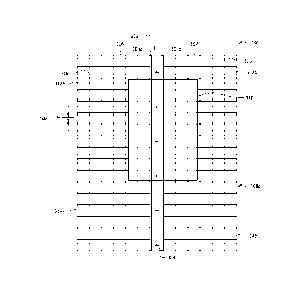
FIGURE 3 illustrates a top view of an example grate track with a center hinge,
in
accordance with certain embodiments. More particularly, FIGURE 3 illustrates
an example grate
track 300 with a center hinge 302. Grate track 300 comprises a first grate
306, a second grate 307,
and center hinge 302. Center hinge 302 comprises hinge edges 303a and 303b
disposed on
opposite longitudinal edges of center hinge 302. In the example embodiment of
FIGURE 3, center
hinge 302 is coupled to first grate 306 along hinge edge 303a and coupled to
second grate 307
along hinge edge 303b. In certain embodiments, center hinge 302 may be a twin
hinge, such that
both first grate 306 and second grate 307 are rotatably coupled to center
hinge 302. For example,
first grate 306 may be rotatably coupled to center hinge 302 via hinge edge
303a and second grate
307 may be rotatably coupled to center hinge 302 via hinge edge 303b. In
certain embodiments,
only one of first grate 306 and second grate 307 may be rotatably coupled to
center hinge 302. For
example, center hinge 302 may be rotatably coupled to first grate 306 via
hinge edge 303a and
9
Date Recue/Date Received 2020-09-10
coupled with second grate 307 on the opposite longitudinal edge of center
hinge 302 via another
type of j oint.
Center hinge 302 may be installed in a transport vehicle (e.g., a railroad
car, a semi-trailer,
a truck, a container, a rack, a deck, etc.) using one or more fasteners 304.
In some embodiments,
fastener(s) 304 may be a round-head fastener, or any other suitable means to
install grate track 300
such that the fastener 304 does not penetrate the tire of the vehicle or
otherwise damage the freight.
In certain embodiments, grate track 300 may be installed in a transport
vehicle having rack posts.
In such a scenario, center hinge 302 may allow portions of first grate 306 and
second grate 307 to
be notched out around the rack posts.
The present disclosure contemplates that grate track 300 may have any suitable
dimensions.
In certain embodiments, a width of first grate 306 may be different from a
width of second grate
307. In certain embodiments, a width of first grate 306 may be the same as a
width of second grate
307. Some non-limiting examples of possible dimensions for elements of grate
track 300 are
described below. It should be understood, however, that the present disclosure
is not limited to
the example dimensions described below.
As one example, first grate 306 and second grate 307 may comprise at least 6
squares in
width with each square being 1 1/2" by 1 1/2", resulting in a total width of
9". As another example,
first grate 306 and second grate 307 may be at least 4 1/2" respectively in
width. Furthermore, in
some implementations a width of center hinge 302 may be equal to a width of
the square of first
grate 306 or second grate 307, which results in a total width of grate track
300 of at least 19 1/2".
In certain embodiments, center hinge 302 may not be at the center of first
grate 306 and
second grate 307. For example, first grate 306 may be 18" in width, second
grate 307 may be 4
1/2" in width, and center hinge 302 may be 1 1/2" in width. In such a case,
grate track 300
advantageously complies with the universal format to accommodate various
freight, from
passenger vehicles to dual real wheel (DRW) light trucks, in standard
containers, racks, and decks.
Advantageously, grate track 300 may be flexible in size by changing the size
of center
hinge 302, first grate 306, or second grate 307 to fit different needs (which
may vary by
implementation). In certain embodiments, first grate 306 or second grate 307
may be 6" or wider.
In certain embodiments, first grate 306 may be the same size as second grate
307. In certain
embodiments, first grate 306 may be wider or longer than second grate 307.
Date Recue/Date Received 2020-09-10
When a chock 310 is applied to grate track 300, chock 310 may be locked/fixed
to both
first grate 306 and second grate 307. In such a scenario, chock 310 is
positioned over center hinge
302, such that an upward force caused by chock 310 during transportation is in
line with center
hinge 302 and may be offset by center hinge 302.
In certain embodiments, first grate 306 and second grate 307 may comprise a
top wire 316
and a bottom wire (not explicitly shown) to form a two-layer grate. Center
hinge 302 may be
recessed below top wire 316 of at least one of the first grate 306 and the
second grate 307, so that
the teeth of chock 310 may engage top wire 316 only to enable chock 310 to
straddle over center
hinge 302. In some embodiments, at least one of first grate 306 and second
grate 307 may have
additional bottom wire(s) (e.g., along the longitudinal axis), so that the
first grate 306 and the
second grate 307 may provide stiffness strength in the longitudinal direction
which is parallel to
the center hinge 302 at 3/4" spacing, instead of 1 1/2".
In certain embodiments, first grate 306 may comprise at least one gap 308a to
keep first
grate 306 staggered and to reduce dead spots in grate 306. In the example
embodiment of FIGURE
3, gap 308 is parallel with the lateral axis of grate track 300. In certain
embodiments, gap 308a
may be implemented to separate first grate 306 into two portions, a first
first-grate portion 312a
and a second first-grate portion 314a. Using gap 308a to separate first grate
306 into first first-
grate portion 312a and second first-grate portion 314a may advantageously
enable first first-grate
portion 312a and second first-grate portion 314a to be operated independently
(e.g., moved
between positions independently as described below in relation to FIGURES 4A-
4C). When
chock 310 is applied to grate track 300, especially a chock with an extended
lock connected by a
strap, the upward force caused by chock 310 would not raise first grate 306
entirely (which could
cause damage to the underside of a vehicle or other freight) because
straddling the end of first
grate 306 may be stopped by the gap 308a. In certain embodiments, second grate
307 may also
comprise at least one gap 308b. In the example embodiment of FIGURE 3, gap
308b is parallel
with the lateral axis of the grate track 300. In certain embodiments, gap 308b
may be implemented
to separate second grate 307 into two portions, a first second-grate portion
312b and a second
second-grate portion 314b. Using gap 308b to separate second grate 307 into
first second-grate
portion 312b and second second-grate portion 314b may advantageously enable
first second-grate
portion 312b and second second-grate portion 314b to be operated independently
(e.g., moved
between positions independently as described below in relation to FIGURES 4A-
4C). In certain
11
Date Recue/Date Received 2020-09-10
embodiments, each of gaps 308a, 308b are staggered with respect to each other
within the grate
track 300. By staggering gaps 308a and 308b, the gaps may be separated by an
appropriate
distance to provide grate track 300 a less-weaved structure, in order to
provide better protection to
the vehicle in transport.
FIGURES 4A, 4B and 4C illustrate an end view of an example grate track with a
center
hinge, in accordance with certain embodiments. More particularly, FIGURES 4A,
4B, and 4C
illustrate an example application of a grate track 400 with a center hinge
402. In the example
embodiments of FIGURES 4A-4C, grate track 400 comprises a first grate 404, a
second grate 405,
and a center hinge 402. First grate 404 comprises a top wire 407a and a bottom
wire 408a forming
a two-layer grate. Similarly, second grate 405 comprises a top wire 407b and a
bottom wire 408b
forming a two-layer grate. Center hinge 402 comprises hinge edge 403a on one
longitudinal side
of center hinge 402 and hinge edge 403b on an opposite longitudinal side of
center hinge 402. As
described above, in certain embodiments one or both of hinge edges 403a, 403b
may rotatably
couple first grate 404 and second grate 405 to center hinge 402, respectively.
In connection with
the example embodiments of FIGURES 4A-4C, only the operation of first grate
404, rotatably
coupled to center hinge 402 via hinge edge 403a, will be described. It should
be understood,
however, that in certain embodiments second grate 405 may also be rotatably
coupled to center
hinge 402 via hinge edge 403b. In such an implementation, it should be
understood that second
grate 405 will operate in an analogous manner to that described below with
respect to first grate
404. Additionally, where gaps are used to separate one or both of first grate
404 and second grate
405 into different portions (as described above in relation to FIGURE 3), each
portion may be
operated in an analogous manner to that described below.
Grate track 400 may be applied to a deck implemented in any vehicles or
trailers for
transportation of vehicles or other suitable types of freight. In FIGURE 4A,
grate track 400 is
applied to a deck 406 (e.g., using one or more fasteners as described above in
relation to FIGURE
3). In FIGURE 4A, first grate 404 is illustrated in a first position 404a. In
FIGURE 4B, when
cleaning or maintenance is needed, an operator may rotate first grate 404 from
the first position
404a to a second position 404b, for example to clean snow, ice, or other
objects trapped underneath
first grate 404. Furthermore, in FIGURE 4C, an operator may also flip over
first grate 404 from
first position 404a to a third position 404c to lay first grate 404 on top of
second grate 405 for
maintenance, such as applying lubricant to hinge edge 403a of center hinge 402
or to replace a
12
Date Recue/Date Received 2020-09-10
new hinge for center hinge 402. In certain embodiments, first grate 404 and
second grate 405 may
be rotated from 00 to 180 . In addition, an operator may easily perform any
routine work or task
for grate track 400 because of the light weight of first grate 404 and second
grate 405. This is
because of placement of center hinge 302 in between first grate 404 and second
grate 405, which
creates smaller sized grates in comparison to existing approaches that use an
outboard hinge and a
single grate. For example, in certain embodiments first grate 404 and second
grate 405 may each
comprise 6 squares in width, which is less than the 13 squares used for a
conventional grate track.
Therefore, grate track 400 is not as heavy as the conventional grate track,
and furthermore, costs
less to manufacture than the conventional grate track.
Indeed, one advantage of certain embodiments described herein is that, by
implementing a
center hinge in the grate track, a cost for manufacturing the grate track and
a weight of the grate
track may be reduced, and a structural strength of the grate track may be
improved. The grate
track with a center hinge as described in the present disclosure may
advantageously resist the pull
forces caused by chocks during transportation. Therefore, a durability of the
grate track may be
prolonged, and a stronger anchor may be provided to the freight during
transportation.
FIGURE 5 is a flowchart illustrating an exemplary method 500, in accordance
with certain
embodiments. Method 500 beings at step 501. At step 501, a grate track
assembly is formed. The
grate track assembly comprises: a first grate; a second grate; and a center
hinge disposed between
the first grate and the second grate. The center hinge is rotatably coupled to
the first grate along a
first longitudinal edge of the center hinge and rotatably coupled to the
second grate along a second
longitudinal edge of the center hinge.
In certain embodiments, the center hinge may comprise a twin hinge. In certain
embodiments, the first grate and/or second grate may comprise a top wire and a
bottom wire
forming a two-layer grate.
In certain embodiments, a width of the first grate may be different from a
width of the
second grate. In certain embodiments, the width of the first grate may be
eighteen inches. In
certain embodiments, the width of the second grate may be four and one-half
inches. In certain
embodiments, a width of the center hinge may be one and one-half inches.
In certain embodiments, a width of the first grate may be the same as a width
of the second
grate.
13
Date Recue/Date Received 2020-09-10
In certain embodiments, the first grate may comprise a first gap separating
the first grate
into a first first-grate portion and a second first-grate portion, the first
gap running parallel to a
lateral axis of the first grate. The second grate may comprise a second gap
separating the second
grate into a first second-grate portion and a second second-grate portion, the
second gap running
parallel to a lateral axis of the second grate. In certain embodiments, a
position of the first gap and
a position of the second gap may be staggered with respect to each other
within the grate track
assembly. In certain embodiments, the first first-grate portion and the second
first-grate portion
may be operable to rotate from a first position to a second position. The
first first-grate portion
may be operable to remain in the first position while the second first-grate
portion is in the second
position. The second first-grate portion may be operable to remain in the
first position while the
first first-grate portion is in the second position.
At step 502, the grate track assembly is affixed to a transport vehicle. In
certain
embodiments, the grate track assembly may be affixed to the transport vehicle
at the center hinge.
For example, the center hinge may be affixed to a deck of the transport
vehicle (e.g., a railcar)
using a plurality of fasteners (e.g., a plurality of round-head fasteners).
In certain embodiments, the method may comprise positioning a vehicle within
the
transport vehicle, the vehicle comprising at least one tire positioned at
least partially on the grate
track assembly affixed to the transport vehicle.
In certain embodiments, the method may comprise securing the vehicle to the
grate track
assembly using a chock positioned over the center hinge on the grate track
assembly and adjacent
to the at least one tire. The chock may comprise an extended lock connected to
the chock by a
strap positioned over the at least one tire. The chock may be locked to both
the first grate and the
second grate.
Although particular embodiments and their advantages have been described in
detail, it
should be understood that various changes, substitutions and alternations can
be made herein
without departing from the spirit and scope of the embodiments. Particular
embodiments of the
present disclosure described herein may be used or mounted for a railroad car,
a semi-trailer, a
truck, a container, a rack, a deck, or any other vehicle for transportation.
Modifications, additions, or omissions may be made to the systems and
apparatuses
described herein without departing from the scope of the disclosure. The
components of the
14
Date Recue/Date Received 2020-09-10
systems and apparatuses may be integrated or separated. Moreover, the
operations of the systems
and apparatuses may be performed by more, fewer, or other components.
Modification, additions, or omissions may be made to the methods described
herein
without departing from the scope of the disclosure. The methods may include
more, fewer, or
other steps. Additionally, steps may be performed in any suitable order.
Although this disclosure has been described in terms of certain embodiments,
alterations
and permutations of the embodiments will be apparent to those skilled in the
art. Accordingly, the
above description of the embodiments does not constrain this disclosure. Other
changes,
substitutions, and alterations are possible without departing from the spirit
and scope of this
disclosure.
Date Recue/Date Received 2020-09-10