Note: Descriptions are shown in the official language in which they were submitted.
CA 03092942 2020-09-02
BLADES PROPELLER MECHANISM OF CENTRIFUGAL PUMP FOR TRANSPORT OF LIQUIDS AND
LIVE
FAUNA
FIELD OF THE INVENTION
The present invention, as expressed in the title of this specification,
belongs to the field of mechanics
and / or biotechnology. Particularly to the central part of a centrifugal
pump: blades propeller
mechanism of centrifugal pump for transporting liquids and wildlife.
OBJECT OF THE INVENTION
The problem to be solved is to obtain a blades propeller mechanism of
centrifugal pump for
transporting liquids and wildlife, which is preferably found in a centrifugal
pump, with a novelty and
inventive functional technical configuration that allows a good flow of fluids
and live species without
damaging them (mainly), efficiently, in large quantities, and also easy to
manufacture, since
currently they are not in the state of the art, such competitive advantages.
Therefore, the object of
the invention is to improve the efficiency and the functional structural
design of the impeller of the
centrifugal pumps, to displace fluids and solids, avoiding damage of mainly
living species.
BACKGROUND
Aquaculture is a food sector that has had an accelerated growth in recent
years, and represents a
large percentage of global fish products destined for food. Currently, there
is a large amount of
thrusters, impellers, pumps, or devices, which operate based on the same
principles of water
pressure and centrifugal forces to move fluids from one place to another, or
simply to increase the
pressure of them.
Our invention, which will be described in later pages, refers to centrifugal
pumps, specifically to a
new impeller (propeller) that will be used mainly for aquaculture, as a feeder
or harvester, for the
displacement of solids (fish, crustaceans, larva, shrimp, among other beings
being alive) contained
in fluids (sea, salt or fresh water) to the other side, without damaging them.
Recently, attention has
been paid to the extraction of live fish and shellfish without damaging them,
however, there are
1
Date Recue/Date Received 2020-09-02
CA 03092942 2020-09-02
deficiencies in the machines that currently exist, in terms of damage caused
to fish and other living
things during transport, in low efficiency that present those that do not harm
both fish and other
living aquatic beings, as well as in their complex manufacturing.
Among the patent information, we have patent 4,768,920 of the US database,
entitled "Method for
pumping fragile or other items in a liquid medium", reveals a pump to displace
fragile items, which
contain a disk impeller that has an unobstructed passage between the pump
inlet and outlet. Such
impeller is smooth and in the center forms a conical vortex. He well mentions
that it is an invention
to move fruits, vegetables, even live fish without damaging them; However, its
efficiency must be
very low because it lacks blades or blades that allow a greater displacement
of liquids/solids.
Patent 4,940,385 of the US database, entitled "Rotary disk pump", shows a
centrifugal pump
characterized by having two parallel disks coaxially arranged in the pump
chamber and connected
to rotate around its central axis, the opposite faces of the disks being
separated a predetermined
distance, where at least one of the opposite faces has a plurality of raised
pallets, these pallets being
smaller than the separation between the disks. This patent well mentions that
the efficiency of this
type of pump is lower than conventional centrifugal pumps that use impellers
with blades or curved
pallets; however, it shows as an advantage good handling of solid materials,
greater stability and
less cavitation problems.
Patent 4,373,860 of the US database, entitled "Submersible hydraulic pump of
axial directed inlet
and tangential outlet" deals with a configuration containing a water vortex
generator, which
conditions the water prior to its entry into the pump. It is a very complex
machine and for the
movement of live fish and shellfish it would not be useful.
The publication in espacenet of CN201621093(U), describes a water impeller
having pallets in the
range of 2 to 10, and the center of the impeller base has a low surface
compared to the one on the
periphery of it, namely, the surface of the cross section of the base plate is
curved or diagonal. With
the modification it is mentioned that the pressure decreases, therefore lower
energy consumption.
2
Date Recue/Date Received 2020-09-02
CA 03092942 2020-09-02
We can also observe the publication in espacenet CN102032193(A) entitled
"Stamped semi-open
impeller and centrifugal pump welding", which shows a design that, according
to the advantages
mentioned therein, improves the efficiency, resistance and stiffness of the
impeller/pump.
The Japanese patent with international publication JP2015052287, raises as
problem of providing a
centrifugal pump capable of suppressing the generation of cavitation, and
capable of improving the
self-priming performance. It presents as a solution a new configuration of
curved blades, which in a
few words, at the extreme part (periphery of the impeller) the blades have a
lowered step surface.
The Japanese patent with international publication JP2004353655, presents a
new functional
technical configuration of the impeller, which each pallet or blade is three-
dimensional, having a
smaller width on the outside compared to the part that is near the center of
the impeller.
The International Patent Publication US6220819, presents a new configuration
of the impeller
pallets or blades which serve to decrease the turbulence of the pump, which
are characterized in
that the central part of the pallets are attached to the upper impeller cover
and the outer part of
the pallets are attached to the bottom cover. They are joined by common
screwing, the pallets have
holes for both ends.
In Mexico there is a patent entitled "Propellant device for movement of fish
and live crustaceans"
that has been granted, MX/ a / 201 1/01 1368, and generally claims the
following: a base, at whose
center is located at least a hollow cylindrical body for assembling the device
with the arrow of an
engine; a cover, in whose center a cross hole is located in whose perimeter is
a fence, said hole
functions as an input for a stream of water that drags solid bodies; and a
flat cutting blade
incorporated in the upper part of the base and below the lid, arranged in a
spiral, with which it forms
a conduit for the movement of solid bodies without damaging them. Despite
being useful in
practice, such an invention is complex to manufacture, high cost, as well as
turbulence in operation
since it is not symmetrical; It is true that it does not harm the fish, but it
is deficient since the
entrance area it has is very smaller, due to the same spiral configuration.
This patent is limited to
certain revolutions, due to its asymmetric configuration.
3
Date Recue/Date Received 2020-09-02
CA 03092942 2020-09-02
As can be seen, the patents of the current state of the art have some
variations that provide some
function different from each other, where sometimes the changes are usually
minimal, but are
considered patents due to the innovative and inventive designs that try to
solve different problems
related to the centrifugal pumps, including the propeller (impeller); It is
worth mentioning that
centrifugal pumps, as well as the impellers themselves, have been and will
continue to be the
subject of study due to the complexity of fluid handling, as well as solids
and living beings present
in them. The mechanical design of centrifugal pumps is always a challenge to
constantly innovate.
DESCRIPTION
The present invention describes a blades propeller mechanism of centrifugal
pump for transporting
liquids and wildlife, which has a novel and inventive functional technical
configuration that provides
a series of advantages and benefits in relation to the state of the art.
Before beginning to describe
the invention in general and detail, it is clarified that the word
"propellant" will be used with
reference to the "impeller" which is normally contained in centrifugal pumps.
So, when we see the
word propellant or impeller, we refer to the same piece here and in the state
of the art. Also, the
same propeller has "blades", which in the state of the art are also known as
"blades", "pallets",
"sheets", among others, however we choose the term "blades".
Our blades propeller mechanism of centrifugal pump for the transport of
liquids and living fauna,
has as main application the transport of water or liquids, as well as live
fauna, for example: shrimp,
fish, mollusks, among others. It is for this reason that it is considered the
invention of the
biotechnological area, as well as the mechanical area. The design of the main
part of a centrifugal
pump is the propellant (or impeller, driving part of the whole body), which
gives it the novelty and
inventive activity, and not only theoretically, but in practice as well.
In order to understand the invention regarding the propeller mechanism of
blades, the operation of
centrifugal pumps that within its body, shell or snail, include the
propellers, whether open, semi-
open or closed, with their multiple configurations regarding the design of
blades, rotating discs, or
even nothing. Now, it is to be understood that the driving part of a
centrifugal type pump is the
propeller itself, and when it rotates it causes the liquid to also rotate and
this imparts centrifugal
force to water particles, causing the water to quickly move outward as
rotational mechanical energy
4
Date Recue/Date Received 2020-09-02
CA 03092942 2020-09-02
and is transmitted to the fluid towards the discharge of the impeller; Both
the pressure and kinetic
energy of the water rise. In the area of suction, the water is being displaced
so a negative pressure
is induced in the eye (center of the propeller), where said low pressure helps
to suck a stream of
liquids and solids (fish, crustaceans, among other living solids or inert,
etc.) again in the system. As
already mentioned, the propellant (impeller) is installed inside a case (snail
body, harvester, or
pump simply), where water with or without solids, which will move outward will
be collected inside
it and continue on its way in the same direction of rotation of the propeller
to discharge fluids and
solids. The body has an increase in surface along the direction of the flow,
said increasing area aids
in the water housing that has just been added and also helps reduce the
velocity of the outflow.
The foregoing being the information required to understand our invention,
where our centrifugal
pump blades propeller mechanism for transporting liquids and wildlife, is
comprised of: a front plate
and a back plate; a propeller suction ring, a deflector admiter; a drive
coupling; a cap for the drive
coupling; at least two blades (the number is variable) where each of them has
a rectangular curved
configuration that extends from the outside of the impeller into the interior
fixed to a circular tube;
a circular tube for each of the blades containing the propeller, where each of
them is coupled to the
inner part of the blade throughout its length, and in turn extends to the
diameter of the suction
ring; the number of blades being proportional with the number of tubes.
This configuration, which will be described in detail below according to the
numbering of the figures,
is of great relevance since it solves very common problems in centrifugal
pumps with blades
propellers. The new design, accommodation and coupling between the impeller
parts, with
emphasis on the blades, circular tubes, deflector admiter and cap, provide a
number of advantages
such as: large load capacity, because there is not much contact area as soon
as the propeller is
entered; variable solids loading size, being able to reduce or increase the
number of blades present;
it does not cause damage to the living species that circulate there due to the
circular, curved and
inclined configurations that occur within the propeller; better load
distribution of both liquids and
solids (live species); more stable centrifugal pump because the impeller is
symmetrical; less damage
to the internal walls of the propeller; damage located in a single piece
according to the use of the
machine, which functions as a "sacrificial ring", being of low cost, easy
replacement and installation:
drive coupling; among others that will be referenced in the detailed
description of the invention
(where the preferred mode is given).
Date Recue/Date Received 2020-09-02
CA 03092942 2020-09-02
BRIEF DESCRIPTION OF THE FIGURES
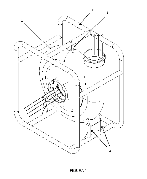
Figure 1.- Isometric view of a snail type centrifugal pump. The path that
follows the flow of liquids
and solids is indicated. Inside is the propulsion mechanism.
Figure 2.- Exploded view of the centrifugal pump, where the blades propeller
mechanism of
centrifugal pump for transporting liquids and wildlife is also shown.
Figure 3.- Isometric view of the blades propeller mechanism of centrifugal
pumpfor the transport of
liquids and wildlife.
Figure 4.- Isometric view of the blades propeller mechanism of centrifugal
pump for the transport
of liquids and wildlife, without front plate, suction ring, or cap.
Figure 5.- Isometric view of the blades propeller mechanism of centrifugal
pump for the transport
of liquids and wildlife, without front plate or suction ring.
Figure 6.- Isometric view of a curved rectangular blade and a straight tube or
cylinder (preferred
modality of the invention). Left image: h represents the height and / or the
length of the blade. Right
image: shows the outside area or part (15a) and the inner part area (15b) of a
curved rectangular
blade.
Figure 7.- Top view of the blades propeller mechanism of centrifugal pump for
the transport of
liquids and wildlife, without a front plate or suction ring, with two blades
and two tubes or cylinders.
Figure 8.- Top view of the blades propeller mechanism of centrifugal pump for
the transport of
liquids and wildlife, without front plate or suction ring, with three blades
and three tubes or
cylinders.
Figure 9.- Top view of the blades propeller mechanism of centrifugal pump for
the transport of
liquids and wildlife, without front plate or suction ring, with four blades
and four tubes or cylinders.
6
Date Recue/Date Received 2020-09-02
CA 03092942 2020-09-02
Figure 10.- Top view of the blades propeller mechanism of centrifugal pump for
the transport of
liquids and wildlife, without front plate or suction ring, with five blades
and five tubes or cylinders.
Figure 11.- Top view of the blades propeller mechanism of centrifugal pump for
the transport of
liquids and wildlife, without front plate or suction ring, with six blades and
six tubes or cylinders.
Figure 12.- Exploded view of the blades propeller mechanism of centrifugal
pump for transporting
liquids and wildlife.
Figure 13.- Top view of a different modality of the blade-cylinder
compilation.
Figure 14.- Top view of a different modality of the blade-cylinder
compilation.
Figure 15.- Top view of a different modality of the blade-cylinder
compilation.
Figure 16.- Top view of a different modality of the blade-cylinder
compilation.
Figure 17.- Top view of a different modality of the blade-cylinder
compilation.
DETAILED DESCRIPTION / PREFERRED MODALITY
The best way to operate the blades propeller mechanism of centrifugal pump for
the transport of
liquids and wildlife is described below, with main utility in the harvest and
collection of products
from the aquaculture sector, such as shrimp, fish, crustaceans, among other
beings Saltwater or
fresh water, this being the main activity carried out by the invention
described herein. It should be
mentioned that the description, detailed description and/or preferred modality
of the invention do
not exclude other possible configurations or applications of the propellant
described herein.
To avoid confusion with the drafting, it's describe bellow the names of the
parts of the entire blades
propeller mechanism of centrifugal pump for transport of liquids and wildlife,
with such numbering
seen in the attached images:
7
Date Recue/Date Received 2020-09-02
CA 03092942 2020-09-02
1) Pump.
2) Harness.
3) Top anchor.
4) Lower anchors.
5) Body, shell or snail body.
6) Inside the pump body.
7) Propulsion mechanism, propellant or impeller.
8) Front suction cover.
9) Packing.
10) Suction zone.
11) Discharge zone.
12) Tube or cylinder.
13) Suction ring.
14) Back plate.
15) Blade.
16) Front plate.
17) Deflector admiter.
18) Drive coupling.
19) Cap.
As already mentioned, our invention is currently used in aquaculture for the
displacement of liquids
and living solids (fish, crustaceans, shrimp, among other living things),
without damaging them.
According to the images, we observe Figure 1, where the centrifugal pump (1)
and a series of
attachments that provide stability and portability thereof, among which we
find a harness (2) that
covers the entire pump ( 1), as well as an upper anchor (3) and the lower
anchors (4) on the left side
and right side of the pump (1). A plurality of arrows can also be seen in the
center and others in the
upper right part of the pump (1) that indicate the flow path followed by
liquids and solids when the
pump is running. So, this is the current external form of where the blades
propeller mechanism of
centrifugal pump for transporting liquids and wildlife is inside. Such a form
may have changes in its
structure, which does not limit the main part of our invention.
8
Date Recue/Date Received 2020-09-02
CA 03092942 2020-09-02
Now, in Figure 2 with exploded view of Figure 1, more components are visible
and internal parts of
the pump are indicated (1). We will name as a snail body (5) the structure or
housing that includes
most of the pieces shown, as well as in its entirety the blades propeller
mechanism of centrifugal
pump for transporting liquids and wildlife. The interior (6) of the body (5)
of the pump is
appreciated; a front suction cover (8) that serves to anchor the intake area
of the product and to
seal with the body (1) (having another back cover that is not seen in the
images, with the same
sealing function, but contains the motor mounting area) and; a gasket (9) to
avoid rubbing metal-
metal, so that it does not rub the suction or intake ring (13, Figure 3) with
the front cover (8), the
gasket (9) being made of plastic material and preventing wear of the metal
parts. The suction zone
(10) of the propeller shows the inlet path (6) of the pump (1) and the
impeller (7), and then be
ejected by the discharge zone (11).
We begin now with the detailed description of our innovative and inventive
centrifugal pump blades
propeller mechanism for the transport of liquids and wildlife, which is
visualized in a detailed and
complete way from Figure 3 to Figure 17. We observe an isometric view in the
Figure 3 of the
propellant mechanism (7); an isometric view of the propeller mechanism (7)
without front plate (16)
or suction ring (13) or cap (1 9) in Figure 4; and in Figure 5 a view without
front plate (16) or suction
ring (13) of our propeller mechanism (7), which comprises the following: at
least one front plate (16)
and one back plate (14) , where the front (16) contains the suction ring (13)
of the propeller (7), and
the back (14) has integrated the drive coupling (motor cover), and both pieces
together contain the
rest of the propeller parts, and both parts together contain the rest of the
propeller parts, forming
part of the flow channel internal; at least one suction ring (13) of the
propeller (7); at least one drive
coupling (18), where the drive shaft is set; at least one cap (19), the start
of the intake deflector (17),
where its special shape serves to cover the area of the drive shaft
(coupling); at least one intake
deflector (17), located at the base of the back plate (14), and has a
pyramidal shape, which gives a
smooth and damping path to the flow; at least two blades (15), where each one
has a rectangular
curved shape with a height (h) which goes from the back plate (14) to the
front plate (16), and with
a length (/) extending from the outside (15a) of the propeller (7) inwards
(15b) and; at least two
tubes or cylinders (12), one of these being for each blade (15) present,
coupled along the entire
height of the inner side (15b) of the blade and extending to the diameter of
the suction ring (13),
being proportional the number of blades (15) with the number of tubes or
cylinders (12).
9
Date Recue/Date Received 2020-09-02
CA 03092942 2020-09-02
Figure 12 shows an exploded view of the blade propeller mechanism, where each
of the parts
thereof can be seen in detail and the location and assembly of each of them
can be fully understood.
To facilitate their understanding, the names are written according to figure
12 (and numbering) from
left to right: suction ring (13), front plate (16), curved rectangular blade
(15), tube or cylinder (12) ,
cap (19), drive coupling (18), deflector admiter (17), and back plate (14).
All these pieces are those
that are part of the blades propeller mechanism of centrifugal pump for
transporting liquids and
wildlife.
From Figure 7 to 11, with a top view of the blade propeller mechanism, it is
intended to facilitate
the understanding of the use of a variable number of blades (15) curved
rectangular and tubes (12),
where the number of tubes (12) is proportional to the number of blades (15).
Figure 7 with two
blades and two cylinders (12); Figure 8 with three blades and three cylinders;
Figure 9 with four
blades and four tubes; Figure 10 with five blades and five tubes; Figure 11
with six blades and six
tubes.
As indicated a few moments ago, the curved rectangular blade (15) along with
its respective tube
or cylinder (12), are a fundamental part of the inventiveness and novelty of
our invention. That tube
or cylinder (12) is said to have a convex shape, and we refer to the curved
surface of the tube or
cylinder (12), which prevents damage to living species at its entrance to the
propeller mechanism
(7); the straight tubes or cylinders being the preferred ones, but there may
also be oblique or
inclined. The tubes or cylinders (12) can also be replaced by a very
pronounced curve or bend
extension of the inner part (15b) of the blade (15) or any other convex shape
that replaces the
curved surface of a tube or a cylinder (12), avoiding damage to living species
at their entrance to
the propellant mechanism (see Figures 13-17).
In Figures 3-12, it is appreciated the curved rectangular blades (15) with
their straight tubes or
cylinders (12), this mode being so far preferred because due to simple
manufacturing and
installation it is decided to integrate the blade (15) a straight cylinder
(12).
Following the detailed description and/or preferred modality of the invention,
it is understood that
on the outside of the curved rectangular blade (15) a convex shape or part
(12) is not required
Date Recue/Date Received 2020-09-02
CA 03092942 2020-09-02
because it would be an obstacle rather than reduce the exit space of the
propellant product (7), also
at this point the solids or living species present are not at risk of being
damaged.
Then, whether they are straight, oblique, inclined tubes or cylinders, some
very pronounced curve
or bend extension of the inner part of the blade as shown in Figures 13-17, or
some other shape or
piece that has a convex or curved design such as so far described, it is and
will be part of the
description and protection claimed by this specification.
According to the aforementioned characteristics, a curved rectangular blade
(15) and its tube or
cylinder (12) (straight, oblique cylinder, tube, some other form such as those
shown in the figures,
or another), is preferably equal to the rest of sets of blades (15) and
cylinders (12), as shown in
Figures 7-1 1 where the number of these varies without structural changes. In
other words, the
tubes or cylinders (12) of the propellant (7) are preferably equal to the rest
of tubes or cylinders
(12); however, they can be of variable size or shape from one blade (15) to
another, or equal to a
certain number of blades (15), as long as a plane of symmetry of the propeller
is respected to
continue to comply with the stability during rotation.
According to the above, we can exemplify with the use of two sets (X) of blade
(15)-cylinder (12)
(preferred modality) with two other sets (Y) of Figure 17, being alternately
"(X) - (Y) - (X) - (Y) "to
respect a symmetrical plane that divides the propeller (in this case 4 blades,
with two different
configurations) into two" (X) - (Y) /1(X) - (Y) ", where each side is the
mirror of the other in order to
respect structural and rotational stability. With this representation it is
understood the way in which
the invention can be carried out in propellants with blades and variable
convex pieces, both in size,
shape or arrangement. Preferably for propellers of even numbers, equal to and
greater than four
blades, to respect the symmetry of a flat cut.
As additional features: it can be seen in the figures that none of the blade
(15) is interposed to the
flow of the successive nor vice versa; The tubes or cylinders (12) are part of
a support that gives
strength to the body of the propeller (7). ; the plates (14, 16) convert the
propellant (7) into one of
the closed type; the cap (19) is the start of the deflector admiter, where its
special shape serves to
cover the area of the drive axis (coupling), and is preferably truncated
conical, being able to be flat,
convex, or other, and also functions as localized wear part, facilitating
replacements and reducing
11
Date Recue/Date Received 2020-09-02
CA 03092942 2020-09-02
maintenance costs; the deflector admiter (17) serves to receive the liquids /
solids and distribute
them evenly inside the propeller, allowing a soft and a cushioned entry.
Finally, after having described each of the parts, functions and advantages of
these, it is of utmost
importance to emphasize that the use of such structural technical
configurations, provide
advantages far superior to the state of the art today. We can realize that the
entrance of the living
species is being cushioned at the entrance, in a novel way, having curved,
convex, inclined surfaces
throughout the central surface that prevent the damage of the species and a
good distribution of
them inside of the propellant or pump. Where according to size, the number of
blades present
would vary. It is important to remember that these propellers or pumps rotate
at high revolutions,
so our invention is optimal for the transport of live species, without
damaging them, compared to
those of the state of the art, in addition to other benefits and utilities
already described.
It is to be understood that the description and modalities described herein
are merely illustrative of
the current preferred accomplishments of the invention, and that there are no
limitations intended
by the construction or design details in this document, other than as
described in the claims
attached. The modifications that may result after taking into account the
present specification, as
well as different uses that may be presented to those mentioned herein, are
included.
12
Date Recue/Date Received 2020-09-02