Note: Descriptions are shown in the official language in which they were submitted.
CA 03093135 2020-09-04
WO 2019/169426 - 1 - PCT/AU2019/000031
AN EXPANDABLE DEVICE, APPARATUS AND ASSEMBLY FOR PUSHING
APART OPPOSED SURFACES
[0001] The present invention relates to an expandable device, apparatus and
assembly
adapted to forcibly separate components with spaced-apart opposed surfaces.
The invention may
find particular application in automotive maintenance, for example, including
for use in
disassembling hub and brake rotor components.
[0002] Metal automotive assemblies, such as brake assemblies in-situ are
often difficult to
separate for inspection, removal and servicing especially if there has been
sustained use and/or
corrosion.
[0003] In particular, inspection, removal and servicing of disc brake hub
and rotor
assemblies for heavy vehicles can be difficult and time-consuming as the used
hub and rotor
assemblies are often seized and do not separate easily. Furthermore, the hub
and rotor assemblies
can be bound together by corrosion especially if heavy vehicles are used on
salted roads during
winter. Current methods for separating these hub and rotor assemblies include
cutting the rotor
by an angle grinder, breaking the rotor with a hammer or separating the
assembly with the use of
a hydraulic press, which can be destructive and result in the violent
separation of the components
or parts thereof All such methods are time-consuming, inconvenient and costly
due to the
manual labour required and as rotor and hub assemblies for a heavy vehicle can
weigh in excess
of 100kg, there are also health and safety concerns for the service
technicians.
[0004] According to a first aspect of the present invention, there is
provided an expandable
device adapted to forcibly separate spaced components having generally
parallel opposed
surfaces defining a cavity therebetween, the expandable device having a jaw
assembly with a pair
of opposing jaws and actuating means for opening the jaws, the actuating means
including a
separating member configured to be driven between the jaws so as to push apart
the jaws such
that the jaws are openable between a contracted configuration where the jaws
are receivable in
the cavity to an expanded configuration where the jaws are forced apart by the
actuating means
such that the outwardly directed surfaces of the jaws are engageable with the
opposed surfaces
and exert oppositely directed forces thereon.
[0005] The separating member may have a pair of inclined surfaces
associated with inwardly
directed surfaces of the jaws, each inwardly directed surface being
correspondingly inclined and
CA 03093135 2020-09-04
WO 2019/169426 - 2 - PCT/AU2019/000031
generally parallel to its associated inclined surface of the separating
member, wherein, when the
separating member is movable laterally between the inner surfaces of the jaws,
the inclined
surfaces of the separating member are slidable along the inclined inwardly
directed surfaces
thereby pushing the jaws apart.
[0006] In embodiments, the separating member is in the form of a wedge.
[0007] The jaw assembly may have a pair of elongate members having opposing
ends, the
jaws being defined by first end portions thereof and being pivotally connected
at opposing
second end portions such that the jaws are movable between the contracted and
expanded
configurations.
[0008] According to an embodiment, the jaws may be pivotally biased towards
each other.
[0009] According to an embodiment, each of the opposed surfaces is a
surface of one of
least two assembled components, such that pushing apart the opposed surfaces
effects separation
of the components.
[0010] According to an embodiment, the actuating means includes a
hydraulically-powered
system for driving the separating member.
[0011] In a second aspect, the present invention provides an apparatus for
pushing apart
spaced-apart generally parallel opposed surfaces, the apparatus being
configured for carrying at
least one expandable device as described above.
[0012] According to an embodiment, the apparatus is for pushing apart
opposed surfaces of
a hub and rotor assembly to effect separation thereof.
[0013] According to an embodiment, the apparatus is configured to be
received in at least a
part of the cavity defined by the spaced-apart opposed surfaces, wherein each
of the opposed
surfaces is one of a surface of a hub and rotor assembly.
[0014] Preferably the apparatus includes a plurality of expandable devices
arranged to exert
forces at equally spaced locations about the axis of the hub and rotor
assembly. According to an
embodiment, the apparatus has a frame which carries two expandable devices.
[0015] According to an embodiment, the apparatus has least one engagement
member for
CA 03093135 2020-09-04
WO 2019/169426 - 3 - PCT/AU2019/000031
engaging with the hub and rotor assembly.
[0016] According to an embodiment, the at least one engagement member is
configured for
engaging an outer circumferential rim of the rotor.
[0017] According to an embodiment, the at least one engagement member is
configured for
receiving a stud of the hub.
[0018] According to an embodiment, the apparatus has at least one handle
for assisting a
user in moving the apparatus.
[0019] According to an embodiment, the apparatus has two handles, wherein
the handles
extend transverse to each other.
[0020] According to a third aspect of the present invention, there is
provided an assembly
comprising two apparatus as described above.
[0021] According to an embodiment, each apparatus is, in use, received in
opposite sides of
the cavity such that the oppositely directed forces exerted by the expandable
devices are
distributed substantially across the opposing surfaces for effective
separation of the hub and
rotor.
[0022] According to an embodiment, the apparatus has a frame comprising a
pair of arms,
each arm for carrying at least one expandable device.
[0023] According to an embodiment, the arms are pivotally connected such
that they are
openable and closable between an open configuration where the arms are adapted
to engage or
disengage from a heavy brake assembly and a closed configuration wherein, when
the apparatus
is received in the cavity, the expandable devices having a circumferentially
distributed
arrangement to provide generally even pressure around the opposed surfaces to
provide effective
separation thereof.
[0024] According to an embodiment, having at least one handle for
manipulation between
the open and closed configurations.
[0025] According to an embodiment, each arm carries two expandable devices.
[0026] According to an embodiment, the expandable devices are configured to
expand at
CA 03093135 2020-09-04
WO 2019/169426 - 4 - PCT/AU2019/000031
substantially the same rate.
[0027] The present invention is described hereinbelow, by way of non-
limiting example
only, with reference to the accompanying drawings, in which:
Figure 1 is a perspective view of a hub and rotor assembly;
Figure 2 is a perspective view of the hub and rotor assembly of Figure 1,
where the
hub and rotor are separated from each other;
Figure 3 is a side view of an expandable device for pushing apart opposing
surfaces
according to an embodiment of the present invention;
Figure 4 is a perspective view of an apparatus for pushing apart a hub and
rotor
assembly according to a second embodiment of the present invention;
Figures 5 and 6 are perspective and front views of the apparatus of Figure 4
in-situ on
a hub and rotor assembly;
Figure 7 is a perspective view of an assembly comprising two apparatus for
pushing
apart a hub and rotor assembly according to a third embodiment of the present
invention;
Figure 8 is a top view of the assembly of Figure 7 mounted on a hub and rotor
assembly; and
Figures 9 and 10 are perspective views of the assembly of Figure 7 in-situ on
a hub
and rotor assembly seen from the hub and rotor sides, respectively.
[0028] A hub and rotor assembly from a heavy vehicle such as a truck or bus
is shown in
Figure 1. The assembly 2 comprises a hub 4 and rotor 6 that are mounted to one
another for
rotation about a common axis, in use. The hub 4 has a series of studs 5
arranged
circumferentially with respect to the rotational axis for attachment to a
vehicle wheel. The rotor 6
forms part of the vehicle braking system. For servicing and replacement of
worn parts, it is
oftentimes necessary to separate the hub from the rotor (as seen in Figure 2)
whilst the assembly
2 is mounted on the vehicle (not shown). However, limited working space and
inadequate tools
make the task of separating the components difficult, particularly where the
hub and rotor have
been bound together by corrosion or the like as described above.
[0029] When mounted together as seen in Figure 1, a circumferential cavity
7 exists between
surfaces of the hub 4 and rotor 6. Embodiments of this invention as seen in
Figures 3 to 10
provide an expandable device 8, apparatus 100,210 and assembly 200 for pushing
apart a pair of
spaced-apart substantially parallel opposing surfaces, which can be used to
exploit the cavity 7 to
CA 03093135 2020-09-04
WO 2019/169426 - 5 - PCT/AU2019/000031
forcibly separate the hub and rotor whilst in situ on the vehicle. Other
applications for the
expandable device, apparatus and assembly may also be apparent to those
skilled in the art from
the disclosure herein.
[0030] As illustrated in Figures 3 to 10, the preferred embodiments of
apparatus 100, 210
and assembly 200 can be used to push apart opposing surfaces of a hub and
rotor assembly 2
shown in assembled and separated configurations respectively in Figures 1 and
2. Although the
apparatus and assembly, which includes one or more expandable devices 8 are
shown and
described in examples involving heavy brake assemblies, it would be
appreciated that the
expandable device, apparatus and assembly, particularly the expandable device
8, could be used
in a variety of applications, including the automotive, manufacturing or
agricultural fields, to
separate opposing surfaces, where each opposing surface is a surface of one of
two components
which have been assembled together and which are generally awkward or
difficult to separate
manually.
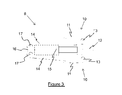
[0031] Referring to Figure 3, the expandable device 8 has a jaw assembly
having a pair of
jaws 10 which are configured to be received in the cavity 7 defined by the
opposed surfaces. The
jaw assembly has two elongate members 14, the ends of which are pivotally
connected side-by-
side to and end member 16. The pivotal connections 17 between the elongate
members 14 and
the end member 16 have parallel pivotal axes such that the opposite ends of
the elongate
members can pivotally move toward and away from one another and thereby define
the pair of
jaws 10. The opposite end of each elongate member 14 supports a bearing member
11, pivotally
coupled to the respective elongate member at 13. The axes of the pivotal
couplings 13 are
parallel to the axes of pivotal connections 17.
[0032] The expandable device 8 has actuating means for driving the jaws 10
from a
contracted configuration in which the elongate members 14 are close to
parallel to an expanded
configuration in which the two bearing members 11 are increased in separation.
In use, in the
contracted configuration the bearing members 11 of the jaws 10 can be inserted
in the cavity 7
defined by the opposed surfaces. Once received in the cavity 7, the jaws 10
can then be expanded
into the expanded configuration such that the outwardly directed surfaces of
the bearing members
11 engage with the inwardly opposed surfaces to exert oppositely directed
forces thereon to push
the opposed surfaces apart. The manner of operation by which the device 8 is
driven from the
contracted configuration to the expanded configuration is explained below.
CA 03093135 2020-09-04
WO 2019/169426 - 6 - PCT/AU2019/000031
[0033] The actuating means includes a linear actuator such as a hydraulic
cylinder 15 located
between the elongate members 14 (obscured portions of the linear actuator 15
are shown in
dashed lines in Figure 3). The linear actuator 15 has one end connected to the
end member 16
and has a separating member 12 mounted on the other end. As illustrated
particularly in Figure 3,
the separating member 12 is wedge-shaped so as to have a pair of angled
surfaces which are
adapted to contact respective inwardly directed surfaces of the bearing
members 11. Each
inwardly directed bearing member surface is correspondingly angled to its
associated angled
surface of the separating member 12. In operation the separating member 12 is
forced between
the bearing members 11 by action of the linear actuator, wherein the angled
surfaces of the
separating member 12 slide along the inwardly angled surfaces of the bearing
members thereby
driving the jaws 10 open, In other words, force is transmitted by the linear
actuator from the end
member 16 to the separating member 12 and the angled surfaces of the
separating member acting
on the bearing members 11 translates the force into expansion of the jaws to
provide the
oppositely directed forces required to push two components apart. The device 8
may include one
or more biasing springs (not seen in the drawings) to urge the jaws toward the
contracted
configuration against the action of the separating member 12.
[0034] The separating member 12, as illustrated in Figure 3, gradually
increases in width
from its tip, thereby forming the pair of angled surfaces to form a wedge. The
inwardly directed
angled surfaces of the bearing members 11 are generally parallel to the
associated surfaces of the
separating member 12 such that, when the separating member 12 is driven
between the bearing
members by the linear actuator, the angled surfaces of the separating member
and bearing
members slide against each other such that expansion of the jaws 10 is smooth
and gradual.
Advantageously, the expansion of the jaws 10 when providing the oppositely
directed forces is
without recoil, which prevents any violent separation of components which
could be harmful or
injurious to the technicians and which may also damage the components.
[0035] Although the linear actuator 15 in the embodiments described herein
takes the form
of a hydraulic cylinder, the means for driving the separating member 12 may be
a pneumatic,
electrical or hydraulically powered system, such as one or more pneumatic or
hydraulic
cylinders, and other driving means are also possible. As illustrated in
Figures 4 to 10, the means
for driving the separating member is a hydraulic cylinder 15, the axis of the
hydraulic cylinder 15
being generally directed between the elongate members 14 of the jaw assembly.
CA 03093135 2020-09-04
WO 2019/169426 - 7 - PCT/AU2019/000031
[0036] Embodiments of the present invention that are described hereinbelow
are specifically
adapted to forcibly separate heavy vehicle rotor and hub assembly components
utilising the
action of at least one expandable device 8 as described above.
[0037] In particular, in the embodiment illustrated in Figures 4 to 6, an
apparatus 100 has a
frame for carrying four expandable devices 8. When the apparatus 100 is
positioned in-situ in the
cavity 7 defined by the opposed surfaces between the hub and rotor assembly 2,
the expandable
ends of the devices 8 are positioned approximately equidistant from one
another in a
circumferential arrangement about the axis of the hub and rotor assembly 2.
This allows for the
oppositely directed forces provided by the expandable devices 8 to be
distributed evenly around
the hub and rotor assembly for effective and smooth separation of the hub 4
and rotor 6.
[0038] The frame of the apparatus 100 includes a pair of arms 110. The arms
110 each have
a pivotal coupling 122 to a link member 120. Each arm 110 carries a pair of
expandable devices
8 mounted between first and second frame plates 111, 112. The expandable
devices 8 each have
respective bearing members 11 attached to the frame plates 111 and 112 whereby
operation of
the expandable devices forces the frame plates away from one another. Contact
plates 115 are
provided at the locations of the expandable device bearing members. The
pivotal coupling
between the arms 110 and link member 120 allows the frame to be opened and
closed by pivotal
movement of the arms relative to the link member, indicated by arrows 140 in
Figure 4. Each
arm 110 has a handle 124 attached to the frame plates to enable manual
manipulation of the arms
by pivotal action as indicated by arrows 130. Manipulation of the handles
effects opening of the
frame for placement of the apparatus on a hub and rotor assembly, and for
removal of the
apparatus therefrom. Once placed on the hub and rotor assembly with the link
member
uppermost, in the absence of force applied to the handles 124 the arm members
will pivot under
gravity toward the closed configuration.
[0039] When the apparatus 100 is opened, placed on a hub and rotor
assembly, and allowed
to return to its closed configuration, the frame plates 111, 112 and jaws of
the expandable
devices 8 are located in the cavity between the hub and rotor positioned such
that the jaws 10 of
each expandable device 8 are distributed evenly around the rotor/hub axis. As
such, the
oppositely directed forces provided by each driven separating member 12 via
the jaws 10 is
applied evenly across the opposing surfaces of the hub and rotor assembly 2
for effective and
efficient separation thereof.
CA 03093135 2020-09-04
WO 2019/169426 - 8 - PCT/AU2019/000031
[0040] Figures 5 and 6 show the apparatus 100 mounted to the hub and rotor
assembly. In
the view shown in Figure 5 it can be seen that the expandable devices 8 of the
apparatus 100 are
close to their maximally expanded configuration, although an additional gap
between the
apparatus 100 and hub 4 is shown for the purposes of illustration.
[0041] The expandable devices 8 are arranged to be connected so as to
operate
simultaneously however it can be appreciated that the expandable devices 8 may
be arranged to
operate independently if required. As illustrated in Figures 4 to 6, the
expandable devices 8 on
each arm 110 are connected together by hydraulic fluid hoses 105 such that the
expandable
devices 8 on each arm 110 operate to expand simultaneously and at the same
rate. Although not
shown in the Figures, the expandable devices 8 on both arms may also be
connected so as to
driven together. It will be appreciated that the hydraulic cylinders 15 can
have connectors (not
shown) to which a hydraulic pump may be connected and disconnected such that
the apparatus
100 is portable and is easily engageable with the components to be separated.
[0042] In the embodiment illustrated in Figures 7 to 10, there is shown an
assembly 200 for
separating components, such as a vehicle hub and rotor assembly by action on a
pair of opposed
surfaces of the respective components. The assembly 200 comprises two
apparatus 210 which are
generally the same although in mirror image. Each apparatus 210 is similar to
one arm 110 of the
preceding embodiment, but the two apparatus 210 are separately mountable
rather than being
pivotally coupled together. Each apparatus 210 includes a frame comprising a
pair of parallel
frame plates 211, 212 with two expandable devices 8 mounted therebetween.
[0043] The two apparatus 210 are adapted to engage on opposing sides of the
hub and rotor
assembly cavity. As such, the oppositely directed forces provided by the
expandable devices 8 of
the two apparatus 210 acting together can be applied evenly around the axis of
the hub and rotor
assembly for effective and efficient separation of the components.
[0044] Advantageously, each of the apparatus 210 carries two expandable
devices 8 and thus
has a reduced weight in comparison to the apparatus 100 which carries all four
expandable
devices 8. This may be beneficial to avoid injury to the technicians during
transport or use. The
apparatus 100 carrying four separation devices is estimated to have a total
mass of about 28 kg
and therefore each apparatus 210 would be about half that weight and would be
more portable,
safer and easier to handle by a service technician.
CA 03093135 2020-09-04
WO 2019/169426 - 9 - PCT/AU2019/000031
[0045] Each apparatus 210 has a pair of handles 224, 225. As exemplified in
Figures 7 to 10,
the handles 224, 225 are defined as elongate portions extending from the frame
plate 211 and are
arranged such that they extend in mutually transverse orientations for ease of
manipulation.
[0046] Each apparatus 210 has at least one engagement member 228, 230 for
locating and
supporting the apparatus 210 on the hub and rotor assembly. In particular, the
engagement
members 228, 230 are configured to engage with accessible portions of the hub
and rotor
assembly so as to be supported by the hub and/or rotor. The engagement members
228, 230 can
also assist in positioning the apparatus 210 correctly within the cavity 7
between the hub 4 and
rotor 6.
[0047] As illustrated more particularly in Figures 7 to 10, each apparatus
210 has first and
second engagement members 228, 230. The first engagement members 228 are
configured to
engage with penultimate studs 5 on either side of the upper most stud of the
hub when the hub
and rotor assembly 2 is in an upright position, as best seen in Figure 9.
Furthermore, the second
engagement member 230 is configured to engage with the rotor 6 such that each
apparatus 210 is
engaged and supported by the outer circumferential rim of the rotor. If the
hub and rotor
assembly is not in an upright position, for example positioned horizontally
such that the axis of
the hub 4 is directed upwardly, then the engagement members 228, 230 can act
primarily to aid
in the correct placement of the assembly 200 in the cavity 7 of the hub and
rotor assembly 2.
[0048] In the example of Figures 7 to 10, the first engagement member 228
is in the form of
an inverted U-shaped portion which extends transversely from the top of the
frame plate 212.
The end of the first engagement member has a hook configured to receive a stud
5.
[0049] As seen best in Figures 8 to 10, the second engagement member 230 is
in the form of
a roller which is configured to engage with an outer circumferential rim of
the rotor 6. The first
and second engagement members 228, 230 are thus arranged to be able to support
each apparatus
210, thereby forming the assembly 200, on the upper portions of the hub and
rotor assembly 2
when it is in an upright position, shown in Figures 9 and 10. As such, when
the expandable
devices 8 are operated the oppositely directed forces provided by the
expanding action of both
apparatus 210 can be applied evenly around the opposing surfaces of the hub
and rotor assembly
102 for effective and efficient separation of the components.
[0050] While various embodiments of the present invention have been
described above, it
CA 03093135 2020-09-04
WO 2019/169426 - 10 - PCT/AU2019/000031
should be understood that they have been presented by way of example only, and
not by way of
limitation. It will be apparent to a person skilled in the relevant art that
various changes in form
and detail can be made therein without departing from the spirit and scope of
the invention.
Thus, the present invention should not be limited by any of the above
described exemplary
embodiments.
[0051] Throughout this specification and the claims which follow, unless
the context
requires otherwise, the word "comprise", and variations such as "comprises"
and "comprising",
will be understood to imply the inclusion of a stated integer or step or group
of integers or steps
but not the exclusion of any other integer or step or group of integers or
steps.
[0052] The reference in this specification to any prior publication (or
information derived
from it), or to any matter which is known, is not, and should not be taken as
an acknowledgment
or admission or any form of suggestion that that prior publication (or
information derived from
it) or known matter forms part of the common general knowledge in the field of
endeavour to
which this specification relates.