Note: Descriptions are shown in the official language in which they were submitted.
CA 03093172 2020-09-04
1
Device comprising a furnace and method for the use thereof
The invention relates to a device comprising a furnace having at least one
furnace
chamber which is delimited by a wall and into which a semi-finished glass
product may
be introduced. The invention also relates to a method for re-shaping semi-
finished glass
products.
It is known in the art to introduce semi-finished glass products into a
furnace where they
are heated and thus re-shaped. For example, vehicle windows or bent
architectural
glass may be manufactured in this way. It is also known to additionally heat
locally the
semi-finished glass product in the furnace with a radiation source so as to
gain greater
control over the shaping process.
A disadvantage of these known devices and methods is the long cycle time of
the
shaping process due to slow heating and cooling of the semi-finished glass
product. In
some embodiments, it is therefore an object of the invention to provide a
device and a
method for re-shaping a semi-finished glass product, which allow shorter cycle
times
and/or improved control over the re-shaping process.
According to the invention, this object is solved by a device according to
claim 1 and a
method according to claim 20. Advantageous improvements of the invention are
described in the dependent claims.
According to the invention, a device is disclosed having a furnace comprising
at least
one furnace chamber that is delimited by a wall. While performing the method,
a semi-
finished glass product is introduced into this furnace chamber and heated. In
some
embodiments of the invention, the heating may be carried out by convection and
radiation until the semi-finished glass product has a sufficiently low
viscosity and is re-
shaped freely or in a mold under the influence of gravity. In other
embodiments of the
invention, the residence time of the semi-finished glass product and/or the
temperature
inside the furnace chamber may be selected in such a way that the semi-
finished glass
product gets a higher temperature but retains a sufficient mechanical strength
which
initially prevents re-shaping. Then, additional heat may be supplied to
predeterminable
Date Recue/Date Received 2020-09-04
CA 03093172 2020-09-04
2
partial areas of the semi-finished glass product. This heat heats the semi-
finished glass
product above the glass transition temperature and thus leads to local re-
shaping.
The above mentioned partial areas may, for example, be heated with infrared
laser
radiation from a laser device. Partial areas to be irradiated may be selected,
for
example, by means of a lens system and/or a mask. In other embodiments of the
invention, the laser device may be rotated or swiveled in order to direct the
beam onto
predeterminable partial areas of the semi-finished glass product. In still
other
embodiments of the invention, the laser radiation may be directed by means of
a
scanner with a movable mirror onto predeterminable partial areas of the semi-
finished
glass product. In this way, the laser beam may be controlled faster since
instead of a
comparatively large and heavy laser or another radiation source, only a
comparatively
small and light mirror has to be moved mechanically.
According to the invention, it is suggested to couple the laser beam into the
furnace
chamber through an opening in the furnace wall. This may have the advantage
that the
radiation source and/or the scanner with the movable mirror or actuators do
not have to
be operated at elevated temperature inside the furnace chamber.
In order to avoid a strong absorption of the laser radiation in the wall of
the furnace
chamber, it is suggested to design the opening in a material-free manner in
the form of
a simple hole. According to the invention, it is suggested not to use a
glazing or another
window to cover said opening.
In some embodiments of the invention, the opening in the furnace wall may be
provided
with at least one gate valve being adapted to temporarily close the opening.
This feature
may allow for reducing heat losses when no electromagnetic radiation is passed
through the opening to heat the semi-finished glass product.
In some embodiments of the invention, the opening in the wall may be provided
with at
least one nozzle being adapted to generate a sealing air flow. In particular,
if the
opening is arranged in the ceiling of the furnace chamber, an emission of warm
air
otherwise occurs since the heated air in the furnace chamber rises up and can
escape
Date Recue/Date Received 2020-09-04
CA 03093172 2020-09-04
3
as if through a chimney. The sealing air flow can counteract this convective
flow and
thus reduce the heat losses of the furnace chamber. Thus, undesired heating of
the
space surrounding the furnace may be avoided. Additionally, the risk of
destruction of
the laser and/or the scanner is avoided or reduced because the temperature
above the
opening is reduced. Finally, the energy consumption for heating the furnace
chamber
may be reduced. Furthermore, in some embodiments of the invention, the
temperature
distribution within the furnace chamber may be more homogeneous, so that the
quality
of the semi-finished glass product re-shaped in the device according to the
invention
may be improved.
In some embodiments, the invention relates to a device wherein the nozzle
being
adapted to generate a sealing air flow is designed as a ring nozzle. In some
embodiments of the invention, the sealing air flow may comprise an inert gas.
In some embodiments, the invention relates to a device wherein the furnace has
a
plurality of furnace chambers which are configured to be passed through
sequentially by
the semi-finished glass product, wherein each furnace chamber may have a
different
temperature.
In some embodiments, the invention relates to a device substantially as
described and
comprising further at least one infrared camera being configured to determine
the
temperature distribution of the semi-finished glass product. The infrared
camera may be
arranged in line with a second opening which may be equipped with a second
nozzle for
generating a second sealing air flow. This feature may improve measuring
accuracy.
In some embodiments, the invention relates to a device substantially as
described and
comprising further at least one embossing die being configured to re-shape the
semi-
finished glass product.
In some embodiments of the invention, said embossing die is arranged in a part
of the
furnace chamber being configured to be heated to a temperature differing from
the
temperature of the remaining parts of the furnace chamber.
Date Recue/Date Received 2020-09-04
CA 03093172 2020-09-04
4
In some embodiments, the invention relates to a device substantially as
described and
comprising further a complementarily shaped counter embossing die being
arranged
opposite the at least one embossing die.
In some embodiments, the invention relates to a device substantially as
described and
comprising further at least one laser which is configured to generate a laser
beam and
to direct it onto predeterminable partial areas of the semi-finished glass
product.
In some embodiments, the invention relates to a device substantially as
described and
comprising further at least one movable mirror being configured to guide the
laser beam
onto predeterminable partial areas of the semi-finished glass product.
In some embodiments, the invention relates to a device substantially as
described and
comprising further a transport pallet and/or a mold having three contact
points, said
contact points being configured to be positioned onto corresponding receiving
devices
of the furnace chamber in an interlocking manner.
In some embodiments of the invention, the center of gravity of the transport
pallet
and/or the mold is located within a triangle spanned by the contact points.
In some embodiments of the invention, the contact points have a V-shaped
support
body and the receiving devices have a round outer cross-section.
In some embodiments of the invention, at least one receiving device is
configured to
receive a plurality of contact points.
In some embodiments, the invention relates to a device substantially as
described and
comprising further at least one air circulation system being configured to
circulate the air
in the oven chamber.
In some embodiments, the invention relates to a device substantially as
described and
comprising further at least one sheet metal heat deflector which is arranged
inside the
furnace chamber and covers at least a part of the furnace wall that is located
on the line
of sight of the semi-finished glass product.
Date Recue/Date Received 2020-09-04
CA 03093172 2020-09-04
In some embodiments, the invention relates to a device substantially as
described and
comprising further a heating unit being configured to bring at least one sheet
metal heat
deflector to a predeterminable temperature.
In some embodiments of the invention, the air circulation system is configured
to
generate an air flow which flows behind at least part of a sheet metal heat
deflector
and/or part of the wall.
In some embodiments, the invention relates to a device substantially as
described and
comprising further a positioning system being configured to move the semi-
finished
glass product within the furnace chamber along at least one axis.
In some embodiments, the invention relates to a device substantially as
described and
comprising further a positioning system being configured to rotate the semi-
finished
glass product within the furnace chamber about at least one axis.
In some embodiments, the invention relates to a method for re-shaping a semi-
finished
glass product, by introducing the semi-finished glass product into a furnace
having at
least one furnace chamber being delimited by a wall.
In some embodiments of the invention, the wall may have at least one opening
and at
least one nozzle being adapted to generate a sealing air flow.
In some embodiments, the invention relates to a method for re-shaping a semi-
finished
glass product, wherein the furnace has a plurality of furnace chambers having
different
temperatures and wherein the semi-finished glass product passes said furnace
chambers sequentially.
In some embodiments, the invention relates to a method for re-shaping a semi-
finished
glass product, wherein the temperature distribution of the semi-finished glass
product is
measured by means of at least one infrared camera.
In some embodiments, the invention relates to a method for re-shaping a semi-
finished
glass product, wherein the semi-finished glass product is re-shaped by means
of at
least one embossing die.
Date Recue/Date Received 2020-09-04
CA 03093172 2020-09-04
6
In some embodiments, the invention relates to a method for re-shaping a semi-
finished
glass product, wherein the at least one embossing die is arranged in a part of
the
furnace chamber having a temperature differing from the temperature of other
parts of
the furnace chamber.
In some embodiments, the invention relates to a method for re-shaping a semi-
finished
glass product, wherein a complementarily shaped counter embossing die is
arranged
opposite the at least one embossing die.
In some embodiments, the invention relates to a method for re-shaping a semi-
finished
glass product, wherein a predeterminable partial area of the semi-finished
glass product
is heated by means of a laser beam generated by at least one laser.
In some embodiments, the invention relates to a method for re-shaping a semi-
finished
glass product, wherein the laser beam is directed onto predeterminable parts
of the
surface of the semi-finished glass product by at least one movable mirror.
In some embodiments, the invention relates to a method for re-shaping a semi-
finished
glass product, wherein the semi-finished glass product is arranged on a
transport pallet
and/or a mold, wherein said mold and/or said transport pallet has three
contact points
on the side facing away from the semi-finished glass product. Said contact
points are
positioned onto corresponding receiving devices of the furnace chamber in an
interlocking manner.
In some embodiments, the invention relates to a method for re-shaping a semi-
finished
glass product, wherein the center of gravity of the transport pallet and/or
the mold is
located within an triangle spanned by the contact points.
In some embodiments, the invention relates to a method for re-shaping a semi-
finished
glass product, wherein the contact points have a V-shaped support body and the
receiving devices have a round outer cross-section.
Date Recue/Date Received 2020-09-04
CA 03093172 2020-09-04
7
In some embodiments, the invention relates to a method for re-shaping a semi-
finished
glass product, wherein at least one receiving device receives a plurality of
contact
points.
In some embodiments, the invention relates to a method for re-shaping a semi-
finished
glass product, wherein the semi-finished glass product is introduced into a
furnace
having at least one air circulation system being configured to circulate the
air in the
furnace chamber.
In some embodiments, the invention relates to a method for re-shaping a semi-
finished
glass product, wherein the semi-finished glass product is introduced into a
furnace
having at least one sheet metal heat deflector being arranged inside the
furnace
chamber and covering at least a part of the wall being located on the line of
sight of the
semi-finished glass product.
In some embodiments, the invention relates to a method for re-shaping a semi-
finished
glass product, wherein the semi-finished glass product is introduced into a
furnace
comprising at least one heating unit which brings at least one sheet metal
heat deflector
to a predeterminable temperature.
In some embodiments, the invention relates to a method for re-shaping a semi-
finished
glass product, wherein the semi-finished glass product is introduced into a
furnace and
wherein an air circulation system generates an air flow that flows behind at
least part of
a sheet metal heat deflector and/or a part of the wall.
In some embodiments, the invention relates to a method for re-shaping a semi-
finished
glass product, wherein the semi-finished glass product is moved within the
furnace
chamber along at least one axis by means of at least one positioning system.
In some embodiments, the invention relates to a method for re-shaping a semi-
finished
glass product, wherein the semi-finished glass product is rotated within the
furnace
chamber about at least one axis by means of at least one positioning system.
Date Recue/Date Received 2020-09-04
CA 03093172 2020-09-04
8
The invention shall be explained in more detail below with reference to the
attached
drawings without limiting the general concept of the invention, wherein
Figure 1 shows a first embodiment of a device according to the invention.
Figure 2 shows a schematic diagram of a second embodiment of a device
according to
the invention.
Figure 3 explains the positioning of the semi-finished glass product in a
first
embodiment.
Figure 4 explains the positioning of the semi-finished glass product in a
second
embodiment.
Figure 5 explains the positioning of the semi-finished glass product in a
third
embodiment.
Figure 6 shows a positioning aid of a transport pallet.
Figure 7 shows the top view of a third embodiment of a device according to the
invention.
Figure 8 shows a further view of the third embodiment of a device according to
the
invention.
Figure 9 shows the cross-section of a fourth embodiment of a device according
to the
invention.
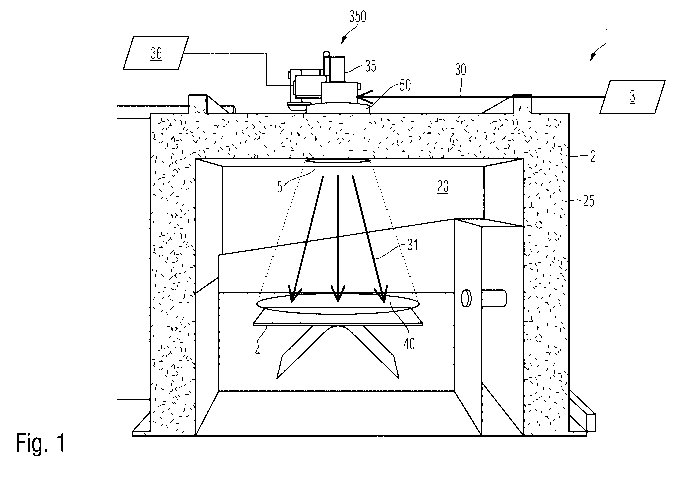
Figure 1 shows a first embodiment of a device according to the invention. The
device
comprises a furnace 2. The furnace 2 comprises a furnace chamber 20, which is
surrounded by a wall 25. The wall can have a thermal insulation in order to
reduce heat
losses to the surroundings. The material of the wall can comprise or consist
of a metal
or an alloy or a mineral material, such as fireclay or ceramics. A metal or an
alloy may
be provided with a heat-insulating coating comprising an oxide or a nitride,
for example.
In addition, the furnace 2 comprises heating units (not shown) being
configured to heat
Date Recue/Date Received 2020-09-04
CA 03093172 2020-09-04
9
the furnace chamber 20. In some embodiments of the invention, the temperature
inside
the furnace chamber 20 may be selected from about 400 C to about 800 C or from
about 500 C to about 700 C.
Figure 1 further illustrates a semi-finished glass product 4. The semi-
finished glass
product may be a flat glass, for example. In other embodiments of the
invention, the
semi-finished glass product 4 may also have a different shape, for example be
a
cylinder, a sphere or have any other geometry.
An opening 5 is arranged in the ceiling of the furnace chamber 20. The opening
5 may
be closed by means of a movable gate valve to reduce or prevent heat losses
resulting
from hot air escaping from the furnace chamber 20. For this purpose, the
movable gate
valve may be made of or comprise a metal or an alloy or a mineral material.
The gate
valve can likewise be provided with a coating.
When the device is operated, the semi-finished glass product 4 is heated to a
predeterminable temperature below the glass transition temperature. In a
subsequent
method step, additional heat may be supplied to predeterminable partial areas
40 of the
semi-finished glass product 4. This is done by infrared radiation, which is
directed to the
desired partial areas 40.
In some embodiments, a laser 3 may be used to generate the infrared radiation.
The
laser may be a CO2 laser in some embodiments of the invention. The laser 3
generates
a laser beam 30. Laser beam 30 may have a power between about 100 W and about
5000 W or between about 1000 W and about 2500 W.
In the illustrated embodiment, the laser beam 30 is directed into the interior
of the
furnace chamber 20 by means of a scanner 350. The scanner 350 has a movable
mirror
35, which may be moved and/or rotated by actuators as known to those skilled
in the
art. In some embodiments, piezo actuators and/or electric motors may be used
to move
and/or rotate the mirror 35. In some embodiments, the mirror 35 of the scanner
350 may
be controlled by a computer system 36, having a computer program stored inside
that is
Date Recue/Date Received 2020-09-04
CA 03093172 2020-09-04
configured to influence the position of the laser beam 31 deflected at the
mirror 35 and
thus selects predeterminable partial areas 40 of the semi-finished glass
product 4.
In order to allow the laser beam 30 to reach the interior of the furnace
chamber 20, an
optional gate valve is removed from the opening 5. This can cause hot air
escaping
from the furnace chamber 20 through the opening 5. According to the invention
it is
suggested to provide at least one nozzle 50 being configured to generate a
sealing air
flow. The nozzle 50 may be designed as a ring nozzle in an exemplary
embodiment.
The sealing air flow generated by the nozzle 50 counteracts the air flow
rising by
convection, so that the escape of hot air from the furnace chamber 20 is at
least
reduced or may be completely prevented. This feature may have the advantage
that the
scanner 350 is exposed to a lower thermal load. In addition, the energy
consumption for
heating the furnace 2 may be reduced and/or the temperature distribution of
the semi-
finished glass product 4 may be more uniform.
Although figure 1 only shows a single opening 5 with a single scanner 350,
some
embodiments of the invention may have a furnace 2 with a plurality of openings
5 each
opening 5 having associated lasers and scanners 350. This feature may have the
technical effect that the area of the semi-finished glass product 4 being
covered by a
plurality of deflected laser beams 31 may be enlarged, so that even large semi-
finished
glass products may be re-shaped, for example truck windows or architectural
glass.
Figure 2 shows a second embodiment of the invention. Like features are denoted
with
like reference numbers, so that the following description may be restricted to
the main
differences. Figure 2 shows a device 1 comprising a furnace 2. The furnace 2
has a
plurality of furnace chambers 20, 21, 22 and 23. The furnace chambers are
arranged
relative to one another in such a way that a semi-finished glass product 4,
which starts
from the first furnace chamber 2, can pass continuously and sequentially
through the
other furnace chambers 20, 22 and 23. The furnace chambers may be kept at
different
temperatures so that the semi-finished glass product 4 undergoes a different
processing
in each furnace chamber. The individual furnace chambers do not have to be
structurally separate in all embodiments. In some embodiments of the
invention, a
Date Recue/Date Received 2020-09-04
CA 03093172 2020-09-04
11
single furnace chamber may be divided into different functional zones having
different
temperatures so that each zone forms one of the furnace chambers 20, 21, 22
and 23.
In the first furnace chamber 21, the semi-finished glass product 4 may be
preheated.
For this purpose, the furnace chamber may have a temperature between 250 C and
about 550 C or between about 400 and about 500 .
The semi-finished glass product 4 is then transferred to the second furnace
chamber
20. This chamber may be at a temperature between about 400 and about 600 .
The re-
shaping may be carried out by local heating using infrared radiation, as
described above
in connection with figure 1. In particular, laser radiation 30 may be used.
Alternatively or additionally, embossing dies 6 may be used, which emboss and
thus
reform the semi-finished glass products 4 at predeterminable parts of the
surface. For
this purpose, the embossing dies 6 may be moved by actuators 65, for example
push
rods, pneumatic actuators, piezo actuators or other actuators known in the
art. The
embossing dies 6 may be preheated to a working temperature which is above the
temperature of the semi-finished glass product 4 and/or above the temperature
of the
furnace chamber 20. For this purpose, the embossing dies 6 may be arranged in
a part
250 of the furnace chamber 20, having a different temperature than the
remaining parts
of the furnace chamber 20 accommodating the semi-finished glass product 4. For
example, the partial volume 250 can comprise additional heating units which
may be
selected from infrared radiators or resistance heaters. In other embodiments
of the
invention, the embossing dies 6 may be equipped with electric heating units.
In some embodiments of the invention, complementarily shaped counter embossing
dies 60 may be disposed opposite the embossing dies 5. In this way, an
unwanted
deformation of the semi-finished glass product 4 under the action of the
embossing die
may be avoided by applying an opposite force by means of the counter embossing
die
6. Alternatively, the counter embossing die 6 may be configured to give the
side of the
semi-finished glass product 4 that is opposite the embossing die 5 a desired
complementary shape.
Date Recue/Date Received 2020-09-04
CA 03093172 2020-09-04
12
After re-shaping has taken place, the semi-finished glass product 4 may be fed
into a
third furnace chamber 22, which, in turn, may have a temperature that differs
from that
of the preceding second furnace chamber 20. For example, the temperature of
the third
furnace chamber 22 may be between the temperature of the first furnace chamber
21
and the temperature of the second furnace chamber 20. In some embodiments of
the
invention, the temperature of the second furnace chamber 20 may be between
about
2000 and about 500 or between about 300 and about 400 .
By storing the semi-finished glass product 4 in the third furnace chamber 22,
the semi-
finished glass product 4 may be cooled in a controlled way so that mechanical
stress
within the semi-finished glass product 4 is reduced. While the semi-finished
glass
product 4 undergoes a controlled cooling in the third furnace chamber 22,
another semi-
finished glass product may be re-shaped in the second furnace chamber 20 and a
third
semi-finished glass product 4 may be preheated in the first furnace chamber
21. Due to
the continuous passage of the semi-finished glass products 4 through the
furnace
chambers 21, 20 and 22, the cycle time may be reduced and the throughput of
the
device 1 may be increased.
In the optional fourth furnace chamber 23, an optional shock cooling of the
semi-
finished glass product 4 may be carried out at a comparatively low
temperature. In this
way, for example, a glass article may be produced from tempered glass which,
on the
one hand, has a hardened surface and therefore becomes more resistant and, on
the
other hand, has a different fracture behavior, so that the occurrence of
large, sharp-
edged fragments is avoided. For this purpose, the fourth furnace chamber 23
can have
a temperature between about -50 C and 100 C, so that the semi-finished glass
product
may be rapidly cooled to a temperature below 350 C. However, it should be
noted that
the fourth furnace chamber 23 is optional and may be omitted in other
embodiments of
the invention. If the fourth furnace chamber 23 is used, the above described
third
furnace chamber 22 can have a temperature between about 650 C and about 750 C
in
preparation for thermal tempering.
Date Recue/Date Received 2020-09-04
CA 03093172 2020-09-04
13
In some embodiments of the invention, the device according to the invention
may have
a transport pallet and/or a mold being configured to move the semi-finished
glass
product inside the furnace chamber 20 and/or between a plurality of furnace
chambers.
In some embodiments of the invention, this transport pallet or mold has three
contact
points, said contact points being configured to be positioned onto
corresponding
receiving devices of the furnace chamber in an interlocking manner. This
allows a
reproducible positioning so that the semi-finished glass product 4 is always
positioned in
the same relative position to the scanner 350 and/or to the embossing die 6.
Thus, the
same partial surfaces of the semi-finished glass product 4 are heated and/or
re-shaped
with high accuracy.
Figure 3 shows a first embodiment of the contact points 71, 72 and 73 of a
transport
pallet. As further detailed in figure 6 below, the contact points 71, 72 and
73 are
designed in such a way that they may be positioned exactly in two directions
and may
be movable in the third direction.
As an example, the corresponding receiving devices 8 of the furnace chamber
may be
made from a polygonal or round tube or rod. Thus, an elongated receiving
device is
provided to accommodate the contact points 71 and 73. These allow the
transport pallet
equipped with contact points 71 and 73 to be positioned in the X direction and
being
movable in the Y direction.
The further receiving device 82 for the contact point 72 is not arranged
parallel to the
first receiving device. In some embodiments of the invention, the receiving
devices 8
and 82 can enclose an angle of about 60 to about 120 or about 90 . The
receiving
device allows the second contact point 72 to be moved in the X direction and a
clear
positioning in the Y direction. Thus, transport pallets may be received in the
furnace and
positioned clearly by the interaction of the three contact points. However,
transport
pallets of different sizes can have different distances between the first and
third contact
points 71 and 72 and a different distance of the second contact point 72 from
the
connecting line of these first and third contact points. This allows the
positioning of
different transport pallets and/or molds, so that different products may be
manufactures
Date Recue/Date Received 2020-09-04
CA 03093172 2020-09-04
14
without any conversion work in the furnace chamber. Cooling of the furnace for
production changeover may therefore be avoided.
Since the transport pallet is not firmly clamped at the contact points but is
movable in
the X and Y direction, even temperature changes, which are unavoidable when a
cold
semi-finished glass product on a cold transport pallet is placed in the heated
furnace,
cannot lead to the occurrence of mechanical stress which could endanger the
dimensional accuracy of the glass component and/or lead to mechanical damage
to the
transport pallet and/or the furnace.
The transport pallets or the molds can rest by gravity on the receiving
devices in the
furnace chamber and can thus also be positioned in a clearly defined manner in
the
spatial direction Z orthogonal to the illustrated X and Y direction. In one
embodiment of
the invention, the center of gravity of the transport pallet and/or the mold
may be located
within the triangle spanned by the contact points 71, 72 and 73. This ensures
a stable
position of the transport pallet within the furnace.
Figure 4 shows a second embodiment of the positioning unit according to the
invention.
Like parts of the invention are denoted with like reference numerals, so that
the
following description may be limited to the main differences.
As shown in figure 4, the receiving device 82 for the second contact point 72
is
designed to be movable parallel to the receiving device 8, so that the angular
relationship to the first receiving device of the contact points 71 and 73
remains
unchanged. However, the receiving device may be moved in a direction parallel
to the
first receiving device 8, so that either an adaptation to different transport
pallets may be
made and/or the transport pallet may be positioned and/or transported within
the
furnace by moving the receiving device 82. For the purpose of illustrating
this feature,
four possible positions of the second receiving device 82 are shown.
Figure 5 shows a third embodiment of the positioning unit according to the
invention.
Like parts of the invention are denoted with like reference numerals, so that
the
following description may be limited to the main differences.
Date Recue/Date Received 2020-09-04
CA 03093172 2020-09-04
The third embodiment uses three receiving devices, 81, 82 and 83 arranged
within the
furnace chamber 20, which each engage in corresponding contact points 71, 72
and 73.
The three receiving devices are again designed as elongated elements, which
may
have a polygonal or round cross-section, for example.
The longitudinal axes of the receiving devices enclose an angle of 1200
relative to each
other. Due to the longitudinal extension, transport pallets and/or molds of
different sizes
or with different distances between the receiving devices may be received
without the
need for conversion work. Nevertheless, the positioning unit allows a
reproducible
positional relationship of the transport pallet equipped therewith to the
other units of the
furnace, for example a scanner 350. This constant positional relationship
includes both
angle and location.
Figure 6 shows a cross section of a segment of a transport pallet 7 with a
contact point
71 and a receiving device 8. In the illustrated, highly simplified exemplary
embodiment,
the transport pallet 7 is a plane-parallel plate comprising a metal or an
alloy or a
ceramic material, for example. Optionally, the transport pallet 7 may be
provided with a
coating (not shown) which prevents the semi-finished glass product 4 from
sticking
and/or increases the temperature resistance.
On the side of the transport pallet 7 that is opposite the semi-finished glass
product 4, a
contact point 71 is shown, which has a polygonal cross-section. The
illustrated cross-
section is obtained by inserting an approximately V-shaped groove into a
cuboid base
body. The groove may have a flattened base.
The corresponding receiving device 8 comprises a rod or tube with an
approximately
circular outer cross-section. Due to the weight of the transport pallet 7, the
V-shaped
groove of the contact point 71 lies on the receiving device in such a way that
it rests on
two dedicated contact points or contact lines 711 and 712. This results in a
defined
positioning in both the X direction and the Z direction which is orthogonal
thereto.
Date Recue/Date Received 2020-09-04
CA 03093172 2020-09-04
16
In cooperation with other receiving devices and contact points, precise
positioning can
thus be achieved in all three directions and all three directions of rotation,
as explained
above with reference to the figures 3 to 5.
Figure 7 shows the top view on a furnace chamber 20, which is delimited by a
wall 25.
Inside the furnace chamber 20, four embossing dies 6 are located, which are
arranged
in a rectangular array concentrically around the target point of a laser beam
30.
Figure 7 illustrates further a semi-finished glass product 4 having an
approximately
rectangular shape. The semi-finished glass product 4 may be moved within the
furnace
chamber 20. Five possible positions are indicated in figure 7. As will be
understood, the
semi-finished glass product 4 may be brought, for example, into a position
allowing all
four embossing dies 6 to act simultaneously or sequentially on the semi-
finished glass
product 4, thereby reaching any point of the semi-finished glass product. In
other
embodiments of the invention, the semi-finished glass product 4 may be moved
under
the laser beam 30 in such a way that predeterminable partial surfaces are
sequentially
heated by the laser beam 30 in order to re-shape the glass product. Due to the
movement of the semi-finished glass product 4 within the furnace 2, the use of
a
scanner 350 may be avoided and a relative movement between the laser beam 30
and
the semi-finished glass product 4 can nevertheless be realized.
Figure 8 shows a further view of a furnace 2 as part of a device 1 according
to the
present invention.
Figure 8 illustrates a top view of the bottom of a furnace chamber 20 of a
furnace 2,
which is delimited by a wall 25. Figure 8 illustrates a mechanism being
configured to
move the semi-finished glass product 4 within the furnace chamber 20. It
consists of two
receiving devices 85, which are arranged approximately parallel to each other.
These
receiving devices may be moved in two axes so that the semi-finished glass
product 4
may be positioned within the furnace chamber 20. This feature allows the semi-
finished
glass product 4 to be moved into the operational range of the embossing dies 6
and/or a
laser beam (not shown in Figure 8). The semi-finished glass product may also
be
Date Recue/Date Received 2020-09-04
CA 03093172 2020-09-04
17
moved to different temperature zones, e.g. to carry out optional method steps
of
preheating, re-shaping or tempering.
Figure 9 illustrates a cross-section through a furnace 2 according to a fourth
embodiment of the invention. Like parts of the invention are denoted with like
reference
numerals, so that the following description may be limited to the main
differences.
Again, a furnace chamber 20 is shown, in which a semi-finished glass product 4
is
accommodated. The furnace 2 is designed as a circulating air furnace, i.e. a
heating
unit (not shown) heats the furnace air and feeds it to the furnace chamber 20
as an air
flow 265 by means of a blower unit. The air flow 265 may allow for a more
homogeneous and uniform heating of the semi-finished glass product 4.
Additionally, a line of sight 45 between individual partial areas of the semi-
finished glass
product 4 and the furnace walls 25 exists. This results in an additional
exchange of
radiant heat between the semi-finished glass product 4 and the wall 25 of the
furnace
chamber 20. Of course, the two lines of sight 45 illustrated in the figure are
only to be
understood as exemplary. In fact, there is a plurality of such lines of sight
between
individual partial areas of the semi-finished glass product 4 and respectively
associated
partial areas of the wall 24 of the furnace chamber 20.
If the wall 25 has a lower temperature than the semi-finished glass product in
the
furnace chamber 20, the exchange of radiant heat leads to a cooling of the
semi-
finished glass product 4. This may prevent a homogeneous heating of the semi-
finished
glass product 4.
According to the invention, it is suggested to place at least one sheet metal
heat
deflectors 255 inside the furnace chamber 20, which may be brought to a higher
temperature than the wall. The sheet metal heat deflectors 255 may be heated,
for
example, by additional electric or gas-operated heating units. In other
embodiments of
the invention, the hot air flow 265 may be used for rear ventilation of a
sheet metal heat
deflector, so that they can absorb heat from the hot air flow 265. In this way
it may be
ensured that the half-space surrounding the semi-finished glass product 4
exchanges
Date Recue/Date Received 2020-09-04
CA 03093172 2020-09-04
18
radiant heat evenly with the semi-finished glass product, so that an
inhomogeneous
cooling or heating of the semi-finished glass product 4 is avoided. Thus, it
is possible to
get a better control of the temperature distribution of the semi-finished
glass product 4
due to the controlled exchange of radiation between the semi-finished glass
product and
the inner walls of the furnace chamber. In some embodiments of the invention,
all sheet
metal heat deflectors 255 inside the furnace chamber 20 may have the same
temperature. In some embodiments of the invention, this temperature may be
equal to
the temperature of the air in the furnace chamber 20.
It is noted that, the invention is not limited to the illustrated embodiments.
The above
description should not be regarded as restrictive but as explanatory. The
following
claims are to be understood in such a way that a cited feature is present in
at least one
embodiment of the invention. This does not exclude the presence of further
features.
Insofar as the claims and the above description define "first" and "second"
embodiments, this designation serves to distinguish between two similar
embodiments
without determining an order.
Date Recue/Date Received 2020-09-04