Note: Descriptions are shown in the official language in which they were submitted.
CA 03093659 2020-09-10
- 1 -
DESCRIPTION
COMPRESSOR AND REFRIGERATION CYCLE APPARATUS
TECHNICAL FIELD
The present disclosure relates to a compressor and a
refrigeration cycle apparatus.
BACKGROUND ART
To prevent over compression and abnormally high
temperature of a compressor body, the temperature of a gas
discharged from the compressor is measured. Patent
Literature 1 (JP-2-241998) discloses a discharge temperature
switch in which a temperature probe of the discharge
temperature switch is disposed at a position downstream of
the compressor body where pulsation of the compressor body
is sufficiently attenuated.
SUMMARY OF THE INVENTION
Technical Problem
However, according to the technique of Patent
Literature 1 described above, the response of the
temperature measurement is sometimes delayed because the
temperature of the discharged gas is not measured
immediately after being compressed. As a result of this, the
reliability of the compressor can be decreased.
Solution to Problem
A compressor of a first aspect includes a casing, a
compression mechanism, a discharge tube, a first temperature
sensor, and a second temperature sensor. The compression
mechanism is disposed inside the casing, compresses a sucked
Date Recue/Date Received 2020-09-10
CA 03093659 2020-09-10
- 2 -
refrigerant, and discharges the compressed refrigerant to a
refrigerant channel formed in an inner space of the casing.
In the discharge tube, the compressed refrigerant flows from
the inner space of the casing to the outside. The first
temperature sensor includes a temperature sensing portion.
The temperature sensing portion is disposed in the
refrigerant channel. The temperature sensing portion
directly measures the temperature of the refrigerant.
"Directly measure" means directly measuring the temperature
of the refrigerant instead of measuring the temperature of a
pipe in which the refrigerant flows or a part that receives
heat transmission from the refrigerant. The second
temperature sensor is disposed at a different position from
the first temperature sensor and measures the temperature of
one of the surface of the discharge tube, an inner space of
the discharge tube, and the surface of the casing. According
to such a configuration, a temperature reflecting an
influence of the heat capacity and heat dissipation of
constituent members of the compressor can be measured, and a
compressor of high reliability can be disposed.
A compressor of a second aspect is the compressor of
the first aspect, and the second temperature sensor measures
the temperature of the surface of the discharge tube.
According to such a configuration, the temperature of the
compressor can be measured with higher accuracy.
A compressor of a third aspect is the compressor of the
first aspect or the second aspect, and the first temperature
Date Recue/Date Received 2020-09-10
CA 03093659 2020-09-10
- 3 -
sensor is disposed to penetrate the casing. In addition, the
first temperature sensor is detachably attached to the
casing from the outside. According to such a configuration,
maintenance can be performed easily.
A compressor of a fourth aspect is the compressor of
any one of the first aspect to the third aspect, and the
temperature sensing portion of the first temperature sensor
is thermally insulated from the casing. According to such a
configuration, the temperature of the refrigerant can be
measured with high accuracy.
A compressor of a fifth aspect is the compressor of any
one of the first aspect to the fourth aspect, and further
includes a guide plate that is disposed inside the casing
and reduces a channel cross-sectional area of the
refrigerant channel. In addition, the first temperature
sensor measures the temperature of a space defined by the
guide plate. According to such a configuration, the
temperature of the refrigerant of high flow rate is
measured, and therefore the responsiveness can be improved.
A compressor of a sixth aspect is the compressor of the
fifth aspect, and further includes a motor that is disposed
below the compression mechanism inside the casing and drives
the compression mechanism. The motor is disposed to form a
refrigerant channel in part of a space between the outer
periphery of the motor and the inner wall of the casing. In
addition, the guide plate is disposed so as to guide the
refrigerant to the refrigerant channel between the outer
Date Recue/Date Received 2020-09-10
CA 03093659 2020-09-10
- 4 -
periphery of the motor and the inner wall of the casing.
According to such a configuration, reduction of size and
cost of the apparatus can be realized.
A compressor of a seventh aspect is the compressor of
the fifth aspect or the sixth aspect, and, in a region near
the inner wall of the casing, the discharge tube is disposed
on the opposite side to a region defined by the guide plate
in plan view. According to such a configuration, the second
temperature sensor can measure a temperature reflecting
information not influenced by the first temperature sensor.
A compressor of an eighth aspect is the compressor of
any one of the first aspect to the seventh aspect, and the
second temperature sensor is disposed within a range where a
channel length from the casing is 1 m or less. According to
such a configuration, influence of heat transfer loss and
heat capacity can be suppressed.
A refrigeration cycle apparatus of a ninth aspect
includes a refrigeration cycle in which the refrigerant
flows in the order of the compressor of any one of the first
aspect to the eighth aspect, a condenser, an expansion
mechanism, and an evaporator. In addition, the refrigeration
cycle apparatus further includes a calculation unit that
calculates the temperature of a refrigerant discharged from
the compression mechanism, by using the first temperature
sensor and the second temperature sensor. According to such
a configuration, a refrigeration cycle apparatus in which
the refrigerant temperature immediately after a discharge
Date Recue/Date Received 2020-09-10
CA 03093659 2020-09-10
- 5 -
port of the compression mechanism can be estimated with high
accuracy can be disposed.
A refrigeration cycle apparatus of a tenth aspect is
the refrigeration cycle apparatus of the ninth aspect, and
the compressor includes a motor that is disposed below the
compression mechanism inside the casing and drives the
compression mechanism. In addition, the refrigeration cycle
apparatus further includes a rotation number control unit
that controls the number of rotations of the motor on the
basis of the temperature of refrigerant calculated by the
calculation unit. According to such a configuration, a
compressor of high reliability can be disposed.
A refrigeration cycle apparatus of an eleventh aspect
is the refrigeration cycle apparatus of the ninth aspect or
the tenth aspect, and further includes an injection pipe, a
flow rate adjustment mechanism, and an opening degree
control unit. The injection pipe is branched from part of a
pipe extending from the condenser to the expansion mechanism
and connects to the compressor. The flow rate adjustment
mechanism adjusts the flow rate of the refrigerant in the
injection pipe. The opening degree control unit controls the
opening degree of the flow rate adjustment mechanism on the
basis of the temperature of refrigerant calculated by the
calculation unit. According to such a configuration, a
refrigeration cycle apparatus of high reliability can be
disposed.
A refrigeration cycle apparatus of a twelfth aspect is
Date Recue/Date Received 2020-09-10
CA 03093659 2020-09-10
- 6 -
the refrigeration cycle apparatus of the eleventh aspect,
and further includes a gasification mechanism that gasifies
a liquid refrigerant flowing in the injection pipe.
According to such a configuration, control can be performed
with higher accuracy such that the discharge temperature
reaches a target value. To be noted, the "gasification" used
herein can be used as long as at least part of the liquid
refrigerant is gasified, and does not necessarily mean
gasifying all of the liquid refrigerant.
BRIEF DESCRIPTION OF THE DRAWINGS
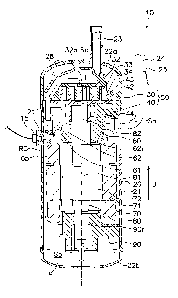
FIG. 1 is a schematic diagram for describing a
configuration of a longitudinal section of a scroll
compressor 10 according to an embodiment.
FIG. 2 is a schematic diagram for describing the
configuration of the longitudinal section of the scroll
compressor 10 according to the embodiment (enlarged view of
a part of FIG. 1).
FIG. 3 is a schematic diagram illustrating a
configuration of a first temperature sensor 15 according to
the embodiment.
FIG. 4 is a schematic diagram illustrating a
configuration of a guide plate 65 according to the
embodiment.
FIG. 5 is a diagram illustrating an example of a test
result of temperature estimation.
FIG. 6 is a diagram illustrating an example of a test
result of temperature estimation.
Date Recue/Date Received 2020-09-10
CA 03093659 2020-09-10
- 7 -
FIG. 7 is a diagram for describing an example of a
configuration of a refrigeration cycle apparatus 100
including the compressor 10 according to the embodiment.
FIG. 8 is a schematic diagram for describing a
configuration of a control apparatus 5 according to the
embodiment.
FIG. 9 is a flowchart for describing opening degree
control of a second expansion mechanism according to the
embodiment.
DESCRIPTION OF EMBODIMENTS
(1) Configuration of Scroll Compressor
FIG. 1 is a schematic diagram for describing a
configuration of a longitudinal section of a scroll
compressor 10 according to an embodiment. FIG. 2 is an
enlarged view of a part of FIG. 1. To be noted, FIGS. 1 and
2 are not precise sectional views, and are sectional views
as viewed in different directions, that is, sectional views
of right side and left side as viewed from the center. In
addition, some parts of constituent members are
appropriately omitted.
As illustrated in FIG. 1, the scroll compressor 10
includes a casing 20, a partitioning member 28, a scroll
compression mechanism 50 including a fixed scroll 30 and a
movable scroll 40, a housing 60, a driving motor 70, a crank
shaft 80, and a lower bearing portion 90.
In the description below, expressions such as "upward"
and "downward" may be used for describing positional
Date Recue/Date Received 2020-09-10
CA 03093659 2020-09-10
- 8 -
relationships and the like of constituent members. Here, the
direction of an arrow U in FIG. 1 will be referred to as an
upward direction, and a direction opposite to the arrow U
will be referred to as a downward direction. In addition, in
the description below, expressions such as "vertical",
"horizontal", "longitudinal", and "lateral" may be used, and
an up-down direction will be referred to as a vertical
direction and also a longitudinal direction.
(1-1) Casing
The scroll compressor 10 includes the casing 20 of a
sealed dome type having an elongated cylindrical shape. The
casing 20 includes a body portion 21 having an approximately
cylindrical shape opening on the upper side and the lower
side, and an upper lid 22a and a lower lid 22b respectively
disposed at the upper end and lower end of the body portion
21. The body portion 21, the upper lid 22a, and the lower
lid 22b are fixed to each other by welding so as to keep
airtightness.
The casing 20 accommodates constituent devices of the
scroll compressor 10 including the scroll compression
mechanism 50, the driving motor 70, the crank shaft 80, and
the lower bearing portion 90. The scroll compression
mechanism 50 is disposed in an upper portion in the body
portion 21. In addition, an oil reservoir space So is
defined in a lower portion of the casing 20. A refrigerating
machine oil 0 for lubricating the scroll compression
mechanism 50 and the like is reserved in the oil reservoir
Date Recue/Date Received 2020-09-10
CA 03093659 2020-09-10
- 9 -
space So.
An inlet tube 23 penetrating through the upper lid 22a
is provided in an upper portion of the casing 20. A lower
end of the inlet tube 23 is connected to an inlet connecting
port of the fixed scroll 30. As a result of this, the inlet
tube 23 communicates with a compression chamber Sc of the
scroll compression mechanism 50 that will be described
later. A low-pressure refrigerant of a refrigeration cycle
before being compressed by the scroll compressor 10 flows
into the inlet tube 23. Then, a gas refrigerant is supplied
to the scroll compression mechanism 50 through the inlet
tube 23.
A discharge tube 24 through which a refrigerant to be
discharged to the outside of the casing 20 passes is
provided in the body portion 21 of the casing 20. A high-
pressure gas refrigerant compressed by the scroll
compression mechanism 50 flows out from an inner space of
the casing 20 to the outside through the discharge tube 24.
To be noted, as the refrigerant of the scroll
compressor 10, for example, R32 can be used.
(1-2) Scroll Compression Mechanism
The scroll compression mechanism 50 is disposed inside
the casing 20, compresses a sucked refrigerant, and
discharges the compressed refrigerant to refrigerant
channels (including refrigerant channels R1 to R3) formed in
the inner space of the casing 20.
Specifically, as illustrated in FIGS. 1 and 2, the
Date Recue/Date Received 2020-09-10
CA 03093659 2020-09-10
- 10 -
scroll compression mechanism 50 includes the fixed scroll 30
disposed above the housing 60 and the movable scroll 40 that
defines the compression chamber Sc in combination with the
fixed scroll 30.
(1-2-1) Fixed Scroll
As illustrated in FIGS. 1 and 2, the fixed scroll 30
includes a fixed-side mirror plate 32 having a flat plate
shape, a fixed-side lap 33 having a spiral shape and
projecting from a front surface of the fixed-side mirror
plate 32, and an outer edge portion 34 surrounding the
fixed-side lap 33. The fixed-side lap 33 is formed to extend
in a spiral shape from a discharge port 32a that will be
described later to the outer edge portion 34. In addition,
an inlet port is provided in the outer edge portion 34 of
the fixed scroll 30. A refrigerant flowing in through the
inlet tube 23 is introduced, through this inlet port, into
the compression chamber Sc of the scroll compression
mechanism 50. To be noted, a check valve that prevents a
backward flow of the refrigerant is provided in the inlet
port.
A discharge port 32a communicating with the compression
chamber Sc of the scroll compression mechanism 50 is formed
at a center portion of the fixed-side mirror plate 32 to
penetrate the fixed-side mirror plate 32 in a thickness
direction. The refrigerant compressed in the compression
chamber Sc is discharged through the discharge port 32a, and
flows into a high-pressure space Si through a first
Date Recue/Date Received 2020-09-10
CA 03093659 2020-09-10
- 11 -
refrigerant channel R1 formed in the fixed scroll 30 and the
housing 60.
(1-2-2) Movable Scroll
As illustrated in FIGS. 1 and 2, the movable scroll 40
includes a movable-side mirror plate 42 having a flat plate
shape, a movable-side lap 43 having a spiral shape and
projecting from a front surface of the movable-side mirror
plate 42, and a boss portion 44 having a cylindrical shape
and projecting from a back surface of the movable-side
mirror plate 42.
Here, the fixed-side lap 33 of the fixed scroll 30 and
the movable-side lap 43 of the movable scroll 40 are
combined such that a lower surface of the fixed-side mirror
plate 32 and an upper surface of the movable-side mirror
plate 42 oppose each other. As a result of this, the
compression chamber Sc is formed between the fixed-side lap
33 and the movable-side lap 43 that are adjacent to each
other. Then, as a result of the movable scroll 40 revolving
around the fixed scroll 30, the volume of the compression
chamber Sc periodically changes. As a result of this, the
refrigerant sucked in through the inlet tube 23 is
compressed in the compression chamber Sc.
The boss portion 44 has a cylindrical shape whose upper
end is closed. An eccentric portion 82 of the crank shaft 80
is inserted in a hollow portion of the boss portion 44. As a
result of this, the movable scroll 40 and the crank shaft 80
are coupled to each other. The boss portion 44 is disposed
Date Recue/Date Received 2020-09-10
CA 03093659 2020-09-10
- 12 -
in an eccentric portion space Sn defined between the movable
scroll 40 and the housing 60. The eccentric portion space Sn
communicates with the high-pressure space 51 through an oil
supply path in the crank shaft 80 or the like, and a high
pressure is applied to the eccentric portion space Sn. As a
result of this pressure, a lower surface of the movable-side
mirror plate 42 in the eccentric portion space Sn is pushed
upward toward the fixed scroll 30. As a result of this, the
movable scroll 40 comes into firm contact with the fixed
scroll 30.
To be noted, the movable scroll 40 is supported by the
housing 60 via an oldham ring. An oldham ring is a member
that prevents rotation of the movable scroll 40 and causes
the movable scroll 40 to revolve.
(1-3) Housing
The housing 60 is press-fitted in the body portion 21,
and an outer peripheral surface thereof is entirely fixed to
the body portion 21 in the peripheral direction. In
addition, the housing 60 and the fixed scroll 30 are fixed
to each other with bolts or the like such that an upper end
surface of the housing 60 is in firm contact with a lower
surface of the outer edge portion 34 of the fixed scroll 30.
In the housing 60, a concave portion 61 recessed in a
center portion of the upper surface and a bearing portion 62
disposed below the concave portion 61 are formed.
The concave portion 61 surrounds the side surface of
the eccentric portion space Sn where the boss portion 44 of
Date Recue/Date Received 2020-09-10
CA 03093659 2020-09-10
- 13 -
the movable scroll 40 is disposed.
In the bearing portion 62, a bearing 62r that rotatably
supports a main shaft 81 of the crank shaft 80 is disposed.
The bearing 62r rotatably supports the main shaft 81
inserted in the bearing 62r.
(1-4) Driving Motor
The driving motor 70 includes a ring-shaped stator 71
fixed to an inner wall surface of the body portion 21, and a
rotor 72 rotatably accommodated inside the stator 71 with a
gap (air gap path) therebetween.
The rotor 72 is coupled to the movable scroll 40 via
the crank shaft 80 disposed to extend in the up-down
direction along the axial center of the body portion 21. The
rotor 72 rotates, and thus the movable scroll 40 revolves
around the fixed scroll 30.
In addition, the driving motor 70 is disposed to form a
refrigerant channel R3 in part of a space between the outer
periphery of the driving motor 70 and the inner wall of the
casing 20. Details of the refrigerant channel R3 will be
described later.
(1-5) Crank Shaft
The crank shaft 80 (drive shaft) is disposed inside the
body portion 21, and drives the scroll compression mechanism
50. Specifically, the crank shaft 80 transmits a driving
force of the driving motor 70 to the movable scroll 40. The
crank shaft 80 is disposed to extend in the up-down
direction along the axial center of the body portion 21, and
Date Recue/Date Received 2020-09-10
CA 03093659 2020-09-10
- 14 -
couples the rotor 72 of the driving motor 70 and the movable
scroll 40 of the scroll compression mechanism 50 to each
other.
The crank shaft 80 includes the main shaft 81 whose
center axis coincides with the axial center of the body
portion 21, and the eccentric portion 82 eccentric with
respect to the axial center of the body portion 21. The main
shaft 81 is rotatably supported by the bearing 62r of the
bearing portion 62 of the housing 60 and a bearing 90r of
the lower bearing portion 90. The eccentric portion 82 is
inserted in the boss portion 44 of the movable scroll 40 as
described above.
Inside the crank shaft 80, an oil supply path is formed
for supplying the refrigerating machine oil 0 to the scroll
compression mechanism 50 and the like. The lower end of the
main shaft 81 is positioned in the oil reservoir space So
formed in a lower portion of the casing 20, and the
refrigerating machine oil 0 in the oil reservoir space So is
supplied to the scroll compression mechanism 50 and the like
through the oil supply path.
(1-6) Lower Bearing Portion
The lower bearing portion 90 is provided in a lower
portion of the body portion 21, and rotatably supports the
crank shaft 80. Specifically, the lower bearing portion 90
includes the bearing 90r on the lower end side of the crank
shaft 80. As a result of this, the main shaft 81 of the
crank shaft 80 is rotatably supported. To be noted, an oil
Date Recue/Date Received 2020-09-10
CA 03093659 2020-09-10
- 15 -
pickup communicating with the oil supply path of the crank
shaft 80 is fixed to the lower bearing portion 90.
(2) Operation of Scroll Compressor
Next, the operation of the scroll compressor 10
described above will be described.
First, the driving motor 70 is activated. As a result
of this, the rotor 72 rotates with respect to the stator 71,
and the crank shaft 80 fixed to the rotor 72 rotates. When
the crank shaft 80 rotates, the movable scroll 40 coupled to
the crank shaft 80 revolves around the fixed scroll 30.
Then, the low-pressure gas refrigerant of the refrigeration
cycle is sucked into the compression chamber Sc through the
inlet tube 23 from the peripheral side of the compression
chamber Sc. As the movable scroll 40 revolves, the inlet
tube 23 and the compression chamber Sc cease to communicate
with each other. Then, as the capacity of the compression
chamber Sc decreases, the pressure in the compression
chamber Sc starts increasing.
The refrigerant in the compression chamber Sc is
compressed as the capacity of the compression chamber Sc
decreases, and eventually becomes a high-pressure gas
refrigerant. The high-pressure gas refrigerant is discharged
through the discharge port 32a positioned near the center of
the fixed-side mirror plate 32. Then, the high-pressure gas
refrigerant flows into the high-pressure space Si through
the refrigerant channel R1 formed in the fixed scroll 30 and
the housing 60, and is discharged through the discharge tube
Date Recue/Date Received 2020-09-10
CA 03093659 2020-09-10
- 16 -
24.
(3) Measurement of Refrigerant Temperature
Next, a configuration for measuring the temperature of
the refrigerant in the scroll compressor 10 described above
will be described.
(3-1) Configuration of Temperature Sensor
The scroll compressor 10 includes a first temperature
sensor 15 and a second temperature sensor 25 for measuring
the temperature of the refrigerant compressed by the scroll
compression mechanism 50.
As illustrated in FIG. 3, the first temperature sensor
includes a temperature sensing portion 15a and a screw-
shaped portion 15n. The temperature sensing portion 15a
includes a thermistor that measures the temperature, and a
15 metal cover that protects the thermistor. The metal is, for
example, copper. As illustrated in FIG. 2, the metal cover
of the temperature sensing portion 15a is disposed to be in
contact with the refrigerant flowing in the second
refrigerant channel R2. In other words, the temperature
sensing portion 15a is disposed so as to directly measure
the temperature of the refrigerant. Here, the second
refrigerant channel R2 is a space continuous from the first
refrigerant channel R1 formed in the housing 60. In
addition, "directly measure" means directly measuring the
temperature of the refrigerant instead of measuring the
temperature of a pipe in which the refrigerant flows or a
part that receives heat transmission from the refrigerant.
Date Recue/Date Received 2020-09-10
CA 03093659 2020-09-10
- 17 -
The first temperature sensor 15 is disposed to
penetrate the casing 20. The first temperature sensor 15 can
be fixed and disposed by being screwed to a screw-in joint
21f provided to the body portion 21 of the casing 20 and by
being sealed. In addition, since the first temperature
sensor 15 is screwed at the screw-shaped portion 15n, the
first temperature sensor 15 can be easily attached from the
outside of the casing 20. In addition, the temperature
sensing portion 15a of the first temperature sensor 15 is
thermally insulated from the casing 20. The first
temperature sensor 15 is disposed at a position near an
outlet port of the refrigerant channel R1 of the housing 60.
To be noted, the temperature sensing portion 15a is formed
from copper or the like having high thermal conductivity. In
addition, the joint 21f is formed from iron or the like
having low thermal conductivity.
The second temperature sensor 25 is disposed at a
different position from the first temperature sensor 15.
Here, as illustrated in FIG. 1, the second temperature
sensor 25 is disposed on the surface of the discharge tube
24, and measures the temperature of the surface of the
discharge tube 24. In addition, the second temperature
sensor 25 is disposed within a range where the length of a
channel from the casing 20 is 1 m or less. Therefore, the
second temperature sensor 25 is disposed on the surface of
the discharge tube 24 within a range of 1 m from the body of
the compressor 10.
Date Recue/Date Received 2020-09-10
CA 030939 2020.0
- 18 -
(3-2) Placement of Guide Plate
The scroll compressor 10 includes a guide plate 65 as
illustrated in FIGS. 1 and 2. The first temperature sensor
15 described above measures the temperature in a space
(second refrigerant channel R2) defined by the guide plate
65.
The guide plate 65 is disposed inside the casing 20,
and reduces the channel cross-sectional area of the second
refrigerant channel R2. Specifically, the guide plate 65 is
disposed to guide the refrigerant to the third refrigerant
channel R3, which is a space defined below the housing 60
and defined in part of the space between the outer periphery
of the driving motor 70 and the inner wall of the casing 20.
In other words, the second refrigerant channel R2 and the
third refrigerant channel R3 are continuous from each other
via the guide plate 65.
To be noted, the guide plate 65 has a shape as
illustrated in FIG. 4, and defines the second refrigerant
channel R2 such that the second refrigerant channel R2 is
concentrated in a part (core cut portion of one pole part of
the stator 71) of the space between the outer periphery of
the driving motor 70 and the inner wall of the casing 20.
Therefore, other core cut portions can be used for oil
return or the like.
(3-3) Calculation of Refrigerant Temperature
The scroll compressor 10 is connected to the control
apparatus 5 that will be described later. The control
Date Recue/Date Received 2020-09-10
CA 03093659 2020-09-10
- 19 -
apparatus 5 functions as a calculation unit 5a that
calculates a temperature estimation value HTp of the
refrigerant at the discharge port 32a on the basis of a
measurement value Tp of the first temperature sensor 15 and
a measurement value Td of the second temperature sensor 25.
Specifically, the control apparatus 5 (calculation unit 5a)
estimates the temperature of the refrigerant on the basis of
the following formula (1). To be noted, K represents a
correction coefficient, and is set on the basis of a
measured value of the refrigerant temperature at the
discharge port 32a measured in an experimental environment.
In addition, n is a natural number.
[Math. 1]
HTp = Tp+ K (Tp ¨Td) n = = = ( 1 )
(3-4) Example of Test of Temperature Estimation
The scroll compressor 10 according to the present
embodiment includes the first temperature sensor 15 and the
second temperature sensor 25 described above and estimates
the refrigerant temperature at the discharge port 32a, and
this is based on the following findings by the present
inventors. In other words, as a result of intensive effort,
the present inventors found that the refrigerant temperature
at the discharge port 32a can be estimated with high
accuracy by using the formula (1) described above.
For example, a result illustrated in FIG. 5 was
obtained for the measurement values of the temperature
sensors when the scroll compressor 10 was controlled. Here,
Date Recue/Date Received 2020-09-10
CA 03093659 2020-09-10
- 20 -
the measured value of the refrigerant temperature at the
discharge port 32a, the measurement value of the first
temperature sensor 15, and the measurement value of the
second temperature sensor 25 are respectively indicated by
lines T, Tp, and Td in FIG. 5. In addition, the temperature
estimation value calculated by using the formula (1)
described above is indicated by a line HTp. To be noted, in
FIG. 5, the horizontal axis represents the time, and the
vertical axis represents the temperature.
Focusing on dotted parts Al and A2 in FIG. 5, it can be
recognized that the line HTp follows well the line T
indicating the measured value, even when sudden temperature
change is caused by change in the performance or the like.
To be noted, the safety can be improved by configuring such
that the error has a positive value when the temperature of
the discharge port 32a, which needs to be protected,
increases.
In addition, a result illustrated in FIG. 6 was
obtained when the horizontal axis was set to represent the
measured value T of the refrigerant temperature at the
discharge port 32a and the vertical axis was set to
represent the temperature estimation value HTp calculated by
using the formula (1) described above. Here, it can be
recognized that the estimation accuracy is approximately
within 10 C.
As described above, it was confirmed that the
refrigerant temperature at the discharge port 32a can be
Date Recue/Date Received 2020-09-10
CA 03093659 2020-09-10
- 21 -
estimated with high accuracy by using the scroll compressor
including the first temperature sensor 15 and the second
temperature sensor 25 described above.
(4) Refrigeration Cycle Apparatus
5 (4-1) Configuration of Refrigeration Cycle Apparatus
FIG. 7 is a diagram for describing an example of a
configuration of the refrigeration cycle apparatus 100
including the compressor 10 according to the present
embodiment.
10 Here, the refrigeration cycle apparatus 100 is a water
heating apparatus and/or cooling apparatus using a heat
pump. Specifically, the refrigeration cycle apparatus 100 as
a water heater or a water cooler supplies heated or cooled
water. In addition, the refrigeration cycle apparatus 100
heats or cools a room by using the heated or cooled water as
a medium.
As illustrated in FIG. 7, the refrigeration cycle
apparatus 100 includes the scroll compressor 10, an
accumulator 102 a four-way switching valve 103, an air heat
exchanger 104, a check valve bridge 109, a first expansion
mechanism 107, a second expansion mechanism (flow rate
adjustment mechanism) 108, an economizer heat exchanger 110,
and a water heat exchanger 111. Further, the refrigeration
cycle apparatus 100 includes a fan 105 for passing air
through the air heat exchanger 104, and a motor 106 that
drives the fan 105. To be noted, the devices and a branching
portion 112 are interconnected by pipes 141 to 154.
Date Recue/Date Received 2020-09-10
CA 03093659 2020-09-10
- 22 -
In addition, each apparatus is controlled by the control
apparatus 5.
To be noted, in the present embodiment, an "expansion
mechanism" refers to one that can reduce the pressure of the
refrigerant, and for example, an electronic expansion valve
and a capillary tube correspond thereto. In addition, the
opening degree of the expansion mechanism can be
appropriately adjusted.
(4-2) Operation of Refrigeration Cycle Apparatus
In the refrigeration cycle apparatus 100, the control
apparatus 5 performs the following control on each
constituent device. To be noted, the control apparatus 5 is
constituted by a microcomputer, a memory storing a program,
and so forth.
(4-2-1) Circulation Control
The control apparatus 5 includes a circulation control
unit 5h as illustrated in FIG. 8, and controls each
constituent device of the refrigeration cycle apparatus 100
to perform control to circulate the refrigerant.
Specifically, the refrigeration cycle apparatus 100 performs
control to circulate the refrigerant when heating or cooling
water.
For example, when water is heated, the gas refrigerant
is delivered to the scroll compressor 10 under the control
of the control apparatus 5. Then, the gas refrigerant is
compressed by the scroll compressor 10. The compressed gas
refrigerant is delivered to the water heat exchanger 111
Date Recue/Date Received 2020-09-10
CA 03093659 2020-09-10
- 23 -
that functions as a condenser. In the water heat exchanger
111, heat is exchanged between the gas refrigerant and
water, and thus the refrigerant is liquified. Subsequently,
the refrigerant is delivered to the first expansion
mechanism 107. The first expansion mechanism 107 reduces the
pressure of the refrigerant. Next, the refrigerant is
delivered to the air heat exchanger 104 that functions as an
evaporator. In the air heat exchanger 104, heat is exchanged
between the refrigerant and air, and thus the refrigerant is
evaporated. Then, the evaporated refrigerant is delivered to
the scroll compressor 10 again. Thereafter, the refrigerant
circulates among the constituent devices of the
refrigeration cycle in a similar manner.
Then, at or after the timing when the circulation of
the refrigerant is started, water is delivered from a water
inlet pipe 161 to the water heat exchanger 111. At this
time, a high-temperature refrigerant is flowing in the water
heat exchanger 111. Therefore, in the water heat exchanger
111, water is heated by the refrigerant. The heated water is
discharged through a water outlet pipe 162. The heated water
is supplied in this manner.
To be noted, the water can be cooled by changing the
flow of the refrigerant by switching the four-way switching
valve 103. In this case, the water heat exchanger 111
functions as an evaporator of the refrigerant.
(4-2-2) Injection Control
The control apparatus 5 includes an injection control
Date Recue/Date Received 2020-09-10
CA 03093659 2020-09-10
- 24 -
unit 5i as illustrated in FIG. 8, and performs injection
control when performing the circulation control described
above. In the refrigeration cycle apparatus 100 according to
the present embodiment, the second expansion mechanism 108,
the economizer heat exchanger 110, the branching portion
112, and the pipes 152 to 154 constitute a so-called
injection circuit.
For example, in the case of heating water, the gas
refrigerant compressed by the scroll compressor 10 is
delivered under the control of the control apparatus 5 to
the water heat exchanger 111 functioning as a condenser. In
the water heat exchanger 111, heat is exchanged between the
gas refrigerant and water, and thus the refrigerant is
liquified. The liquified refrigerant is branched at the
branching portion 112 and delivered to the second expansion
mechanism 108.
Here, the second expansion mechanism 108 functions as a
flow rate adjustment mechanism. Specifically, under the
control of the control apparatus 5, the opening degree and
the like of the second expansion mechanism 108 is adjusted.
As a result of this, the flow rate of the branched
refrigerant is adjusted. At this time, the pressure and
temperature of the refrigerant is reduced as a result of a
throttling-expansion effect of the second expansion
mechanism 108. Then, the refrigerant is delivered from the
second expansion mechanism 108 to the economizer heat
exchanger 110.
Date Recue/Date Received 2020-09-10
CA 03093659 2020-09-10
- 25 -
The economizer heat exchanger 110 functions as a
gasification mechanism. Specifically, in the economizer heat
exchanger 110, heat is exchanged between the refrigerant
flowing from the pipe 153 to the pipe 154 (refrigerant
flowing in the injection circuit) and the refrigerant
flowing from the pipe 147 to pipe 146 (refrigerant flowing
in the main refrigeration cycle), and thus the refrigerant
flowing from the pipe 153 to the pipe 154 (refrigerant
flowing in the injection circuit) is gasified. Then, the
gasified refrigerant is injected during compression by the
scroll compressor 10. As a result of this, the discharge
temperature of the gas refrigerant compressed by the scroll
compressor 10 is adjusted so as not to be excessively high.
To be noted, the "gasification" in the injection circuit
used herein is satisfied as long as at least part of the
liquid refrigerant is gasified (gas-rich state), and does
not necessarily mean gasifying all of the liquid
refrigerant.
(4-2-3) Rotation Number Control of Driving Motor
The control apparatus 5 includes a rotation number
control unit 5b as illustrated in FIG. 8, and controls the
number of rotations of the driving motor 70. Specifically,
the rotation number control unit 5b controls the number of
rotations of the driving motor 70 such that the temperature
estimation value HTp of the refrigerant calculated by the
calculation unit 5a described above reaches a discharge
target temperature.
Date Recue/Date Received 2020-09-10
CA 03093659 2020-09-10
- 26 -
For example, in the case of supplying water of high
temperature, the control apparatus 5 performs control such
that the number of rotations of the driving motor 70 of the
scroll compressor 10 increases. As a result of this, the
amount of circulation of the refrigerant in the
refrigeration cycle increases, and the amount of heat
dissipation from the refrigerant in the water heat exchanger
111 per unit time increases. As a result of this, the
temperature of the water with which heat is exchanged
increases, and water of high temperature can be supplied. To
be noted, the control apparatus 5 stops the rotation of the
driving motor 70 when the temperature of the water is higher
than a set temperature.
(4-2-4) Opening Degree Control of First Expansion Mechanism
The control apparatus 5 includes a first opening degree
control unit 5c as illustrated in FIG. 8, and controls the
opening degree of the first expansion mechanism 107.
Specifically, the first opening degree control unit Sc
controls the opening degree of the first expansion mechanism
107 on the basis of the temperature estimation value HTp of
the refrigerant calculated by the calculation unit 5a
described above.
For example, the control apparatus 5 performs control
such that the opening degree of the first expansion
mechanism 107 increases in the case where the estimation
value of the discharge temperature of the refrigerant
discharged from the scroll compressor 10 is higher than a
Date Recue/Date Received 2020-09-10
CA 03093659 2020-09-10
- 27 -
target discharge temperature. As a result of this, the flow
rate of the refrigerant passing through the air heat
exchanger 104 increases, and the degree of superheating of
the refrigerant sucked into the scroll compressor 10
decreases. Therefore, the discharge temperature of the
refrigerant becomes closer to the target discharge
temperature.
In addition, the control apparatus 5 may control the
opening degree of the first expansion mechanism 107 such
that the degree of subcooling of the refrigerant at an
outlet portion of the water heat exchanger 111 or the degree
of subcooling of the refrigerant at an outlet portion of the
economizer heat exchanger 110 reaches a target degree of
subcooling.
(4-2-5) Opening Degree Control of Second Expansion Mechanism
The control apparatus 5 includes a second opening
degree control unit 5d as illustrated in FIG. 8, and
controls the opening degree of the second expansion
mechanism 108.
Specifically, the opening degree of the second
expansion mechanism 108 is controlled by a procedure
illustrated in FIG. 9. First, the calculation unit 5a of the
control apparatus 5 obtains the measurement value Tp of the
first temperature sensor 15 (S1). In addition, the
calculation unit 5a obtains the measurement value Td of the
second temperature sensor 25 (S2). Here, the timings of the
step Si and the step S2 may be revered or the same. Then,
Date Recue/Date Received 2020-09-10
CA 03093659 2020-09-10
- 28 -
the calculation unit 5a calculates the temperature
estimation value HTp of the refrigerant at the discharge
port 32a of the scroll compression mechanism 50 from the
measurement value Tp of the first temperature sensor 15 and
the measurement value Td of the second temperature sensor 25
(S3). Next, the second opening degree control unit 5d of the
control apparatus 5 controls the opening degree of the
second expansion mechanism 108 on the basis of the
temperature estimation value HTp of the refrigerant
calculated by the calculation unit 5a described above (S4).
For example, the control apparatus 5 performs control
such that the opening degree of the second expansion
mechanism 108 increases in the case where the estimation
value of the discharge temperature of the refrigerant
discharged from the scroll compressor 10 is higher than the
target discharge temperature. As a result of this, the flow
rate of the refrigerant flowing into the injection circuit
increases, and the temperature of the refrigerant sucked
into the scroll compressor 10 is reduced. Therefore, the
discharge temperature of the refrigerant becomes closer to
the target discharge temperature.
(5) Features
(5-1)
As described above, the scroll compressor 10 of the
present embodiment includes the casing 20, the scroll
compression mechanism 50, the discharge tube 24, the first
temperature sensor 15, and the second temperature sensor 25.
Date Recue/Date Received 2020-09-10
CA 03093659 2020-09-10
- 29 -
Here, the first temperature sensor 15 includes the
temperature sensing portion 15a. The temperature sensing
portion 15a is disposed in the second refrigerant channel
R2. The temperature sensing portion 15a is capable of
directly measuring the temperature of the refrigerant
(measurement value Tp). "Directly measure" means directly
measuring the temperature of the refrigerant instead of
measuring the temperature of a pipe in which the refrigerant
flows or a part that receives heat transmission from the
refrigerant. Therefore, temperature quickly following the
change of the discharge temperature immediately after the
discharge port 32a of the scroll compression mechanism 50
can be measured by using the first temperature sensor 15.
In addition, the second temperature sensor 25 measures
the temperature of the surface of the discharge tube 24
(measurement value Td). Therefore, temperature reflecting an
influence of the heat capacity of constituent members of the
scroll compressor 10 can be measured by using the second
temperature sensor 25.
Therefore, in the scroll compressor 10 of the present
embodiment, by using the two temperature values measured by
the first temperature sensor 15 and the second temperature
sensor 25, the temperature of the refrigerant immediately
after the discharge port 32a of the scroll compression
mechanism 50 (temperature estimation value HTp) can be
estimated with high accuracy. As a result, the scroll
compressor 10 of high reliability can be disposed.
Date Recue/Date Received 2020-09-10
CA 03093659 2020-09-10
- 30 -
Here, additional description will be given on the
effect of the scroll compressor 10 of the present
embodiment. In the scroll compressor 10, constituent members
therein may be damaged when the discharge temperature of the
refrigerant becomes excessively high, and therefore control
is performed such that the discharge temperature of the
refrigerant does not exceed a predetermined value. Further,
as a first method for performing the control described
above, there is a method of measuring the temperature of the
discharge tube 24 extending from the casing 20 of the scroll
compressor 10 and estimating a value corrected in
consideration of heat loss or the like as the discharge
temperature. In addition, as a second method, there is a
method of disposing a temperature sensor at the position of
the discharge port 32a of the scroll compressor 10 where the
temperature becomes the highest, and estimating the
measurement value thereof as the discharge temperature.
In the case of the first method, delay or retardation
of response to temperature change derived from the heat
capacity of the casing 20 or the like of the scroll
compressor 10, or temperature reduction derived from heat
dissipation to the surroundings occurs. Here, the amount of
temperature change greatly differs depending on the
operation conditions. Therefore, in some cases, the
temperature at the discharge port 32a of the scroll
compressor 10 cannot be accurately estimated. As a result,
in some cases, the discharge temperature exceeds an
Date Recue/Date Received 2020-09-10
CA 03093659 2020-09-10
- 31 -
acceptable upper limit, and the scroll compressor 10 may be
damaged. Alternatively, in some cases, an excessively large
error is taken into consideration for ensuring reliability,
thus the compressor is overdesigned, and the cost may
increase. In addition, as a result of setting the upper
limit of the discharge temperature to be low, in some cases,
an operation allowable area of the compressor may become
small, or the operation of the scroll compressor 10 may be
inefficient. Further, in some cases, cooling is performed by
liquid injection or the like such that the temperature at
the discharge port 32a does not exceed the upper limit.
However, in some cases, the timing of the cooling is delayed
due to the delay in the response of temperature measurement,
and superheating occurs or discharge wetting occurs due to
subcooling. As a result, the reliability of the scroll
compressor 10 may be degraded in some cases.
Meanwhile, using the second method to resolve the
problems of the first method can be also considered.
However, in the second method, a temperature sensor needs to
be disposed inside the casing 20 of the scroll compressor
10. Therefore, attaching the temperature sensor is
complicated, and the cost increases. In addition, due to a
structure for attaching the temperature sensor near the
discharge port 32a, leakage of refrigerant, loss of
pressure, and the like sometimes occur inside the
compressor. In addition, since the temperature sensor is
exposed to a high-temperature high-pressure atmosphere,
Date Recue/Date Received 2020-09-10
CA 03093659 2020-09-10
- 32 -
malfunction is likely to occur. Further, once malfunction
occurs, a problem arises that, for example, the temperature
sensor cannot be easily replaced.
The scroll compressor 10 according to the present
embodiment includes the two temperature sensors, that is,
the first temperature sensor 15 that is disposed in a
refrigerant channel in the casing 20 and directly measures
the temperature of the refrigerant and the second
temperature sensor 25 that measures the surface temperature
of the discharge tube 24, and therefore can calculate the
discharge temperature of the refrigerant with high accuracy.
As a result, the problems that arise in the first method and
the second method described above can be avoided, and the
scroll compressor 10 of high reliability can be disposed.
(5-2)
In addition, in the scroll compressor 10 according to
the present embodiment, the first temperature sensor 15 is
disposed to penetrate the casing, and is detachably attached
to the casing 20 from the outside. Therefore, maintenance
can be easily performed even if the first temperature sensor
15 is out of order. In addition, since a structure in which
the first temperature sensor 15 can be easily replaced is
employed, the durability does not need to be considered more
than necessary. As a result, the production cost can be
suppressed.
(5-3)
In addition, in the scroll compressor 10 according to
Date Recue/Date Received 2020-09-10
CA 03093659 2020-09-10
- 33 -
the present embodiment, the temperature sensing portion 15a
of the first temperature sensor 15 is thermally insulated
from the casing 20. Therefore, the temperature of the
refrigerant can be measured with high accuracy.
(5-4)
In addition, the scroll compressor 10 according to the
present embodiment further includes the guide plate 65 that
is disposed inside the casing 20 and reduces the channel
cross-sectional area of the refrigerant channel. Here, since
the guide plate 65 is disposed such that the channel cross-
sectional area is reduced, the flow rate of the refrigerant
in that space increases. Then, the first temperature sensor
measures the temperature in the space (second refrigerant
channel R2) defined by the guide plate 65. Therefore,
15 according to such a configuration, the temperature of the
refrigerant of high flow rate is measured, and therefore the
responsiveness can be improved.
(5-5)
In addition, in the scroll compressor 10 according to
the present embodiment, the driving motor 70 is disposed to
form the third refrigerant channel R3 in part of the space
between the outer periphery of the driving motor 70 and the
inner wall of the casing 20. In addition, the guide plate 65
is disposed so as to guide the refrigerant to the third
refrigerant channel R3 between the outer periphery of the
driving motor 70 and the inner wall of the casing 20.
Therefore, the scroll compressor 10 can be manufactured in a
Date Recue/Date Received 2020-09-10
CA 03093659 2020-09-10
- 34 -
small size. Specifically, according to the configuration
described above, a core cut portion of the outer periphery
of the driving motor 70 can be used as a channel. Therefore,
no additional space needs to be provided, and thus reduction
of the size and cost of the scroll compressor 10 can be
realized.
To be noted, here, the guide plate 65 is disposed such
that the refrigerant is concentrated in part (core cut
portion of one pole portion) of the space between the outer
periphery of the driving motor 70 and the inner wall of the
casing 20. Therefore, other core cut portions can be used
for oil return or the like.
(5-6)
In addition, in the scroll compressor 10 according to
the present embodiment, among a region near the inner wall
of the casing 20, the discharge tube 24 is disposed
approximately on the opposite side to the region defined by
the guide plate 65 in plan view. According to such a
configuration, the second temperature sensor 25 can measure
a temperature reflecting an influence that is not reflected
in the first temperature sensor 15. In addition, the first
temperature sensor 15 can measure a temperature not greatly
reflecting an influence of the heat capacity of constituent
members of the scroll compressor 10. Meanwhile, the second
temperature sensor 25 can measure a temperature greatly
reflecting the influence of the heat capacity of constituent
members of the scroll compressor 10. Therefore, the
Date Recue/Date Received 2020-09-10
CA 03093659 2020-09-10
- 35 -
temperature measurement value of the second temperature
sensor 25 reflects an influence not reflected in the first
temperature sensor 15.
(5-7)
In addition, in the scroll compressor 10 according to
the present embodiment, the second temperature sensor 25 is
disposed within the range where the length of a channel from
the casing 20 is 1 m or less. According to such a
configuration, influence of heat loss and heat capacity can
be suppressed.
(5-8)
As described above, in the refrigeration cycle
apparatus 100 according to the present embodiment, the water
heat exchanger 111 and the air heat exchanger 104 can be
respectively used as a condenser and an evaporator. In this
case, the refrigeration cycle apparatus 100 has a
refrigeration cycle in which the refrigerant flows in the
order of the scroll compressor 10, the condenser (water heat
exchanger 111), the first expansion mechanism 107, and the
evaporator (air heat exchanger 104).
Here, the refrigeration cycle apparatus 100 further
includes the calculation unit 5a that calculates the
temperature of the refrigerant discharged from the scroll
compression mechanism 50, by using the first temperature
sensor 15 and the second temperature sensor 25.
Therefore, the refrigeration cycle apparatus 100 can
estimate the refrigerant temperature immediately after the
Date Recue/Date Received 2020-09-10
CA 03093659 2020-09-10
- 36 -
discharge port 32a of the scroll compression mechanism 50
with high accuracy.
(5-9)
In addition, the refrigeration cycle apparatus 100
according to the present embodiment further includes the
rotation number control unit 5b that controls the number of
rotations of the driving motor 70 on the basis of the
temperature of the refrigerant calculated by the calculation
unit 5a. According to such a configuration, the
refrigeration cycle apparatus 100 of high reliability can be
disposed.
For example, the pressure in a high-pressure state can
be reduced by reducing the number of rotations of the
driving motor 70 under the control of the rotation number
control unit 5b. As a result of this, the discharge
temperature can be lowered, and problems such as
deterioration of oil and damage to mechanical parts can be
avoided.
(5-10)
In addition, the refrigeration cycle apparatus 100
according to the present embodiment further includes the
pipes 152 to 154 (injection pipes), the second expansion
mechanism 108 (flow rate adjustment mechanism), and the
second opening degree control unit 5d. Here, the pipes 152
to 154 are branched from a pipe extending from the water
heat exchanger 111 (condenser) to the first expansion
mechanism 107, and are connected to the scroll compressor
Date Recue/Date Received 2020-09-10
CA 03093659 2020-09-10
- 37 -
10. The second expansion mechanism 108 adjusts the flow rate
of the refrigerant in the pipes 152 to 154. The second
opening degree control unit 5d controls the opening degree
of the second expansion mechanism 108 on the basis of the
temperature of the refrigerant calculated by the calculation
unit 5a. According to such a configuration, the
refrigeration cycle apparatus 100 of high reliability can be
disposed.
For example, by estimating the discharge temperature
with high accuracy, occurrence of superheating, discharge
wetting, or the like derived from response delay of
temperature measurement can be avoided.
(5-11)
In addition, the refrigeration cycle apparatus 100
according to the present embodiment further includes the
economizer heat exchanger 110 (gasification mechanism) that
gasifies the liquid refrigerant flowing in the pipes 152 to
154. According to such a configuration, control can be
performed with higher accuracy such that the discharge
temperature of the refrigerant reaches a target value.
(5-12)
To be noted, the refrigeration cycle apparatus 100
according to the present embodiment is suitable for a use in
which the temperature of the refrigerant discharged from the
scroll compressor 10 needs to be high. Particularly, in the
case of using R32 as the refrigerant, since the discharge
temperature is high, the refrigeration cycle apparatus 100
Date Recue/Date Received 2020-09-10
CA 03093659 2020-09-10
- 38 -
according to the present embodiment is suitably used. For
example, the refrigeration cycle apparatus 100 according to
the present embodiment is suitably applied to a water-
heating air-heating machine using a heat pump, as a
substitute for a combustion heater.
(6) Modification Examples
(6-1)
In the description above, the scroll compressor 10 and
the control apparatus 5 have been described as separate
apparatuses, but part or all of the functions of the control
apparatus 5 may be incorporated in the scroll compressor 10.
In other words, the scroll compressor 10 may have the
function of estimating the temperature of the refrigerant at
the discharge port 32a.
(6-2)
Although the second temperature sensor 25 has been
described as the temperature sensor measuring the
temperature of the surface of the discharge tube 24 in the
description above, the second temperature sensor 25 is not
limited thereto. Specifically, the second temperature sensor
may be disposed at a different position from the first
temperature sensor 15 and measure the temperature of one of
the surface of the discharge tube 24, an inner space of the
discharge tube 24, and the surface of the casing 20. Even if
25 the second temperature sensor 25 is disposed in these
positions, the temperature of the refrigerant at the
discharge port 32a can be estimated with high accuracy by
Date Recue/Date Received 2020-09-10
CA 03093659 2020-09-10
- 39 -
using the measurement value of the first temperature sensor
15 in combination.
(6-3)
Although the refrigeration cycle apparatus 100 has been
described as heating or cooling water in the description
above, the refrigeration cycle apparatus 100 is not limited
thereto. For example, the refrigeration cycle apparatus 100
may heat and cool a brine as a fluid different from water,
or heat and cool a room as a direct-expansion air
conditioner by using an indoor unit in which the water heat
exchanger is replaced by an air heat exchanger.
(6-4)
Although the description above has been given by
describing the scroll compressor 10, the compressor is not
limited thereto. The compressor according to the present
embodiment may be a different compressor such as a rotary
compressor.
<Other Embodiments>
Embodiments have been described above, and it should be
understood that the embodiments and details can be modified
in various ways without departing from the gist and range of
the scope of claims.
In other words, the present disclosure is not limited
to the original embodiments described above. The present
disclosure can be materialized by modifying the constituent
elements within the range not departing from the gist
thereof at the stage of implementation. In addition, the
Date Recue/Date Received 2020-09-10
CA 03093659 2020-09-10
- 40 -
present disclosure can make up various disclosures by
appropriately combining a plurality of constituent elements
disclosed in the embodiments described above. For example,
some constituent elements may be eliminated from all the
constituent elements described in the embodiments. Further,
constituent elements may be appropriately combined with a
different embodiment.
REFERENCE SIGNS LIST
5: control apparatus
5a: calculation unit
5b: rotation number control unit
Sc: first rotation number control unit
5d: second opening degree control unit (opening degree
control unit)
5h: circulation control unit
5i: injection control unit
10: scroll compressor
20: casing
15: first temperature sensor
15a: temperature sensing portion
24: discharge tube
25: second temperature sensor
50: scroll compression mechanism
65: guide plate
70: driving motor
100: refrigeration cycle apparatus
104: air heat exchanger (condenser)
Date Recue/Date Received 2020-09-10
CA 03093659 2020-09-10
- 41 -
107: first expansion mechanism (expansion mechanism)
108: second expansion mechanism (flow rate adjustment
mechanism)
110: economizer heat exchanger (gasification mechanism)
111: water heat exchanger (condenser)
152: pipe (injection pipe)
153: pipe (injection pipe)
154: pipe (injection pipe)
R1: first refrigerant channel
R2: second refrigerant channel
R3: third refrigerant channel
CITATION LIST
PATENT LITERATURE
PTL 1: JP2-241998
Date Recue/Date Received 2020-09-10