Note: Descriptions are shown in the official language in which they were submitted.
87192887
1
CARDBOARDTRAYWITWMPROVEDSEAL
FLANGES, AND RELATED METHOD
The invention relates to a cardboard tray folded
from an unfolded sheet of cardboard.
In the packaging industry there is trend to reduce
the amount of plastics used in packaging. Currently, still a
large amount of plastic trays are used to package vegetables,
fruits and precooked meals. Some of the plastic trays are
exchanged for cardboard trays, which are flow packed with
foil.
With flow packed cardboard trays, the look and feel
of the packaging still resembles more a plastic tray than a
cardboard tray. As a result attempts are made to top seal a
cardboard tray, such that only the opening of a cardboard tray
is closed of by a sea] foil.
In order to top seal a cardboard tray, a horizontal
peripheral flange is provided along the access opening of the
tray. Typically, the cardboard tray is folded out of a
unfolded sheet. The flanges of such a tray are sheet parts
folded into a horizontal plane to provide a circumferential
horizontal flange. When a foil is top sealed onto this flange,
the foil will tend to pull the flanges towards each other,
such that the top seal foil is no longer under tension. As the
top seal foil is no longer under tension, the top sealed
cardboard trays cannot be stacked on top of each other.
A further disadvantage of the flanges being pulled
towards each other is that the cardboard tray loses rigidity,
which detracts from the look and feel of the packaging.
Connecting the flange parts of a cardboard tray is
virtually impossible with current conical gluing systems, for
example sold by the company Heiber und Schroder. Due to the
weak flanges, which tend to fold back upwards, a magazine of
gluing system cannot keep the flange parts of a folded tray in
Date Recue/Date Received 2022-02-08
87192887
2
such position, that the flange parts can be adhered together.
Furthermore, overlapping flange parts are
disadvantageous for top sealing a foil, which typically
requires a flat horizontal circumferential flange, due to the
difference in thickness of the flange part itself and the
overlapping flange portion, which are twice as thick.
US 2944721 discloses a cardboard tray folded from an
unfolded sheet of cardboard. The cardboard tray comprises a
top edge composed out of four elongate parts connected
parallel to each other and to the top edge of the walls.
The first, second and third elongate parts provide
in cross-section a triangular shape, while the fourth elongate
part is adhered to the wall and secures the triangular shape
in position.
Due to the triangular cross-section and because the
top edge extends along the full circumference of the tray, a
ridged top edge is provided, which does not allow for any
flexibility. Furthermore, the top edge is not suitable to be
provided with a top seal, as the top edge having the
triangular cross-section is not suitable for arrangement in a
top sealer.
Accordingly, it is an object of the invention to
provide a cardboard tray, in which the above mentioned
disadvantages are reduced or even removed.
For example, in trays for packaging fruit and
vegetables, the top seal foil does not need to be adhered to a
circumferential flange. When the foil is only adhered to the
first flange parts and the top seal foil is tensioned due to
the first, second and third flange part sections, then a
suitable tray is obtained, which can be stacked and wherein
the fruit and vegetables are contained.
Date Recue/Date Received 2022-02-08
87192887
3
Because the first flange parts are double folded
flange part sections additional strength is obtained.
Furthermore, the second flange part section is folded against
the first flange part section and extends on both ends, such
that the extending portions overlap with an adjacent second
flange part of an adjacent wall part. As a result a
circumferential flange is formed by alternately second flange
parts and first flange part sections of the first flange
parts. Because the extending portions of the second flange
part sections, which are folded double and therefore offset
over at least the thickness of the cardboard, provide the
connection with the second flange parts of adjacent walls, a
flat circumferential flange is obtained without any height
differences, such that a top foil can be reliably sealed
thereto. The arrangement of the top foil ensures that the tray
obtains strength.
As the top seal foil is arranged on the
circumferential flange, it is also easy to separate the
plastic from the cardboard to discard the waste separately.
If the cardboard is made of sugar cane, the
cardboard may even be disposed as biodegradable waste. The top
seal foil could he made out of polyactic acid (PLA) such that
the full packaging can be disposed of as biodegradable waste.
However, a more common plastic for the seal foil will be a
polyethylene (PE) - polyethylene terephthalate (PET) laminate.
In a preferred embodiment of the cardboard tray
according to the invention the first flange parts further
comprise a third elongate flange part section, which third
elongate flange part section is connected parallel and along
an elongate edge to the second elongate flange part section
and wherein Lhe Lhird elongale flange parL sect...ion is adhered
Date Recue/Date Received 2022-02-08
CA030M5632021
WO 2019/179930 PCT/EP2019/056684
4
to the outside of the respective wall part.
With the third elongate flange adhered to the
outside of the respective wall part, the position of the first
flange part section is secured. Especially when a top foil is
sealed to the circumferential flange, the third elongate
flange prevents the first flange part section from being
folded up, such that the sealed top foil remains under tension
and sealed cardboard trays according to the invention can
easily be stacked.
The position at which the third flange part section
is adhered to the outside of the respective wall part, allows
for determining the angle of the first flange part section. By
having the first flange part section hanging downwards, the
tension on a top seal foil can be reliably maintained and even
be increased. When the cardboard tray is arranged in a top
sealer, the first flange part section will be urged towards a
horizontal position, when the top foil is sealed to the
flange. When the sealed tray is removed from the top sealer,
the first flange part section will bend back towards the
downwards hanging position, which will further tension the top
seal foil.
The first, second and third flange part sections
also provide strength to the tray, which allows for a
reduction of the thickness of the unfolded cardboard sheet,
for example to a thickness of only 300 micron. The reduced
thickness has the additional advantage that heat penetrates
the cardboard more quickly allowing for a faster connection of
the overlapping parts of the second flange part section and
the second flange part when a heat seal adhesive is used.
In this embodiment, the second flange parts are not
required. For example, in trays for packaging fruit and
vegetables, the top seal foil does not need to be adhered to a
circumferential flange. When the foil is only adhered to the
CA030M5632021
WO 2019/179930 PCT/EP2019/056684
first flange parts and the top seal foil is tensioned due to
the first, second and third flange part sections, then also a
suitable tray is obtained, which can be stacked and wherein
the fruit and vegetables are contained.
5 Preferably, the first elongate flange part section
is sloping downwards from the respective wall part towards the
second elongate flange part section.
The sloping first elongate flange part section
allows for additional tension in the top seal foil, when
arranged on the circumferential flange of the tray.
In a further preferred embodiment of the cardboard
tray according to the invention the width of the first
elongate flange part section is larger than the width of the
second elongate flange part section.
This ensures that when the first flange part is
double folded, the second flange part section does not
contacts the outside surface of the wall part and does not
push the first flange part section upwards.
Preferably, the width of the second elongate flange
part section is the thickness of the cardboard less than the
thickness of the first elongate flange part section. Such
width difference would typically be 0,5 millimeters or more.
In the embodiment, where a third flange part section
is provided, the unfolded sheet can be arranged in an
available folding machine, for example sold by Heiber und
Schroder, which folding maching folds the first flange part
double and adheres the third flange part section to the
outside of the respective wall part. Due to the width
difference between the first and second flange part sections,
the first flange part section will automatically be bend
downwards, such that additional tension in a top foil can be
achieved.
In yet another embodiment of the tray according to
CA030M5632021
WO 2019/179930 PCT/EP2019/056684
6
the invention the extending portions of the second flange part
section are adhered to the second flange parts of adjacent
wall parts.
By adhering the extending portions and second flange
parts together, a strong flange is obtained also with the top
seal foil removed from the circumferential flange.
An additional advantage of the double folded first
flange part, is that the overlapping parts of the second
flange part section and the second flange part can be provided
with a heat seal coating or a suitable polyethylene laminate,
which can be applied to the unfolded sheet from a single side.
Once the folded cardboard tray is arranged in a top sealer and
heat is applied to seal a foil to the circumferential flange,
the coated overlapping parts are also subjected to heat and
pressed together, such that a strong and rigid circumferential
flange is provided, which allows for a top seal to be arranged
under tension and which provides a strong cardboard tray.
In another embodiment of the cardboard tray
according to the invention adjacent wall parts are connected
to each other by at least one overlapping glue flap arranged
to one of the two adjacent wall parts and being adhered to the
other of the two adjacent wall parts.
The connection via glue flaps provides further
strength and rigidity to the tray of the invention.
In yet another embodiment of the cardboard tray
according to the invention corner parts are arranged between
each of two adjacent wall parts and the bottom wall, which
corner parts are folded double and adhered to one of the two
adjacent wall parts.
The corner parts ensure that the bottom wall and
wall parts can be folded out of an unfolded sheet, without
providing any cuts. The resulting tray is therefor fully
closed along the adjacent wall parts and along the wall parts
87192887
7
and the bottom wall. So, a cardboard tray according to this
embodiment will not leak due to the construction of double
folded corner parts.
In a further preferred embodiment a plastic liner is
arranged on the unfolded sheet and each double folded corner
part is sealed by this plastic liner to one of the two
adjacent wall parts.
The additional plastic liner further improves the
leak-tight construction of the cardboard tray and allows even
for storage of more fluid foodstuff. The plastic liner can
also be used to adhere the double folded corner parts to the
wall parts, such that an additional adhesive is not necessary.
In still a further preferred embodiment, the
cardboard tray of the invention a top seal foil is arranged on
the flange parts to cover the tray.
The invention also relates to a method for arranging
a top seal foil on a cardboard tray according to the
invention, wherein a third elongate flange part section is
provided, which method comprises the steps of:
- providing a top sealer;
- providing a cardboard tray as described herein,
wherein the first elongate flange part section slopes downward
towards the outer edge of the flange part;
- arranging the cardboard tray in the top sealer
such that the first elongate flange part is pressed to an
horizontal position;
- providing a top seal foil over the cardboard tray;
- sealing the top seal foil to the first and second
flange parts.
By arranging the cardboard tray with downward
sloping first elongate flange part section in the top sealer,
the first flange parts will be urged towards a horizontal
position. After the top seal foil is arranged on the
Date Recue/Date Received 2022-02-08
87192887
8
circumferential flange and the tray is removed from the top
sealer, the first flange parts will try to move back towards
the downward sloping position causing additional tension in
the top seal foil. The resulting trays with tensioned top
seal foil are easily stackable, without damaging the content
of the tray.
According to an embodiment, there is provided method
for arranging a top seal foil on a cardboard tray, which
method comprises the steps of:
- providing a top sealer;
- providing a cardboard tray folded from an unfolded
sheet of cardboard, which tray comprises:
- a bottom wall with a circumferential edge composed
out of an even number of straight edges;
- wall parts each arranged to a straight edge of the
bottom wall;
- first flange parts alternately arranged to
subsequent wall parts along the circumferential edge, which
flange parts are arranged to an edge of said wall part
opposite of the respective straight edge of the bottom wall;
wherein the first flange parts comprise at least a first, a
second, and a third elongate flange part section, which are
connected parallel and along an elongate edge to each other,
wherein, for each first flange part, the first elongate
flange part section is arranged to a respective wall part,
the third elongate flange part section is connected parallel
and along an elongate edge to the second elongate flange
part section, the third elongate flange part section is
adhered to the outside of the respective wall part, and the
second flange part section is double folded against the
first flange part section, wherein for each first flange
part, the first elongate flange part section is sloping
downwards from the respective wall part towards the second
Date Recue/Date Received 2022-02-08
87192887
8a
elongate flange part section;
- arranging the cardboard tray in the top sealer
such that the first elongate flange part section is pressed
to a horizontal position;
- providing a top seal foil over the cardboard tray;
- sealing the top seal foil to the flange parts.
According to another embodiment, there is provided
cardboard tray folded from an unfolded sheet of cardboard,
which tray comprises:
- a bottom wall with a circumferential edge composed
out of an even number of straight edges;
- wall parts each arranged to a straight edge of the
bottom wall;
- first and second flange parts alternately arranged
to subsequent wall parts along the circumferential edge,
which flange parts are arranged to an edge of said wall part
opposite of the respective straight edge of the bottom wall;
wherein the first flange parts comprise at least a first and
a second elongate flange part section, which are connected
parallel and along an elongate edge to each other, wherein,
for each first flange part, the first elongate flange part
section is arranged to a respective wall part and the second
elongate flange part section is double folded against the
first elongate flange part section, and wherein, for each
first flange part, the second elongate flange part section
extends on two ends in longitudinal direction beyond the
first elongate flange part section and overlaps with second
flange parts of adjacent wall parts, wherein the first
flange parts further comprise a third elongate flange part
section, which third elongate flange part section is
connected parallel and along an elongate edge to the second
elongate flange part section and wherein the third elongate
flange part section is adhered to the outside of the
Date Recue/Date Received 2022-02-08
87192887
8b
respective wall part, wherein for each first flange part,
the first elongate flange part section is sloping downwards
from the respective wall part towards the second elongate
flange part section.
These and other features of the invention will be
elucidated in conjunction with the accompanying drawings.
Figure 1 shows a top view of an unfolded sheet for a
cardboard tray according to the invention.
Figure 2 shows in perspective view the unfolded
sheet of figure 1 folded to a cardboard tray according to
the invention.
Figures 3A and 3B show a schematic cross-sectional
view of the folding of the first flange part.
Figure 4 shows a cross-sectional view along the line
IV-IV in figure 2.
Figures 5A - 5C show schematic cross-sectional views
of the method according to the invention.
Figure 6 shows a top view of an unfolded sheet for a
second embodiment of a cardboard tray according to the
invention.
Figure 7 shows a top view of an unfolded sheet for a
third embodiment of a cardboard tray according to the
invention.
Figure 1 shows an unfolded sheet 1 for a cardboard
tray according to the invention. The unfolded sheet 1 has a
bottom wall 2 with a circumferential edge composed out of
straight edges 3.
Wall parts 4 are arranged to each straight edge 3.
The wall parts 4 are provided with glue flaps 5 to connect
adjacent wall parts 4 together.
The wall parts 4 are alternately provided with
Date Recue/Date Received 2022-02-08
CA030M5632021
WO 2019/179930 PCT/EP2019/056684
9
either first flange parts 6 or second flange parts 7. The
second flange parts 7 are composed out of a single section,
while the first flange parts 6 have a first flange part
section 8 arranged to the respective wall part 4, a second
flange part section 9 and a third flange part section 10.
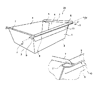
Figure 2 shows in perspective view an embodiment of
a cardboard tray 20 according to the invention folded from the
unfolded sheet 1 shown in figure 1.
The wall parts 4 are folded up and connected via
glue flaps 5. The first flange part 6 has the second flange
part section 9 double folded against the bottom surface of the
first flange part section 8, while the third flange part
section 10 is adhered to the respective wall part 4.
The second flange part section 9 has on both ends
extending portions 21, which extend in longitudinal direction
beyond the first flange part section 8. The extending portions
21 overlap with the ends of the second flange part V.
Preferably, the overlapping parts of the second
flange part section 9 and the second flange part 7 are coated
with a heat seal coating, such that the overlapping parts can
be adhered to each other with a top sealer.
Figures 3A shows how the first flange part 8, 9, 10
is folded using a conical erector device or conical gluing
system, for example sold by the company Heiber und Schroder.
The first, second and third flange part sections are folded
into a Z-shape and the third flange part section is adhered to
the respective wall part 4.
After the adhesive is set, the first and second
flange part sections are bend towards a horizontal position.
However, due to the width difference between the width wl of
the first flange part section and the width w2 of the second
flange part section, the first flange part section remains
sloping downwards towards the outside of the tray 20.
CA030M5632021
WO 2019/179930 PCT/EP2019/056684
Figure 4 shows a cross-sectional view along the line
IV-IV in figure 2. The second flange part 7 is in line with
the respective wall part 4. It is further clear that the
extending portions 21 extend beyond the first flange part
5 section 8, such that the second flange part 7 can be folded
onto these extending portions 21 and that a circumferential
flange is provided composed out of the second flange parts 7
and the first flange part sections 8.
Figure 5A shows a first step of an embodiment of the
10 method according to the invention. A cardboard tray 20 as
shown in figure 2, is arranged in a top sealer having a lower
ring 22 and a top ring 23. Either or both rings 22, 23 are
heated. A top seal foil 24 is furthermore provided over the
tray 20.
The first flange part section 8 slopes downward,
because the width of the first flange part section 8 is larger
than the second flange part section 9, such that when the
third flange part section 10 is adhered to the outside of wall
4, the first flange part section 8 is urged into a downward
sloping position.
In figure 5B, both rings 22, 23 are pressed
together, such that the first flange part 8, 9, 10 and the
second flange part 7, as well as the top seal foil 24 are
pressed together. This pressing action causes the first flange
part 8, 9, 10, which generally slopes downward, to a
horizontal position and the respective wall part 4 to bulge
outwardly.
After sealing the top foil 24 to the first flange
part section 8 and the second flange part 7, and after sealing
the overlapping parts of the flange parts 6, 7, the tray 20 is
removed as well as the pressure by the rings 22, 23. As a
result, the bulging wall part 4 will straighten and the second
flange part section 9 and the overlapping second flange part 7
CA030M5632021
WO 2019/179930 PCT/EP2019/056684
11
will return to the downward sloping position, such that the
top seal foil 8 is further tensioned, such that cardboard
trays 20 according to the invention can be stacked.
Figure 6 shows a second embodiment 30 of an unfolded
sheet, which can be folded into a box according to the
invention. The sheet 30 is similar to the sheet 1 as shown in
figure 1 and similar features are designated with the same
reference signs.
The unfolded sheet 30 has in stead of glue flaps 5,
corner parts 31 arranged between each of two adjacent wall
parts 4 and the bottom wall 2. The corner parts 31 each
comprise a folding line 32, which extends from the bottom 2.
This allows for the corner part 31 to be folded double and
against one of the adjacent walls 4.
As a result of the corner parts 31, a leak-tight
tray is provided, when the unfolded sheet 30 is folded.
Preferably, a foil 33 is laminated to at least the wall parts
4, the bottom wall 2 and the corner parts 31, such that even
an airtight tray can be obtained.
The flanges 6, 7 are folded and adhered in the same
way as with the unfolded sheet 1 and as explained with regard
to figures 1 - 5.
With the corner parts 31 a strong tray can be
provided which allows for packaging a cake, which can be baked
while being arranged in the tray. The strong walls due to the
corner parts prevent bulging, such that a well shaped cake
will be obtained.
Figure 7 shows a top view of an unfolded sheet 50
for a third embodiment of a cardboard tray, which unfolded
sheet can be folded into a box according to the invention.
The unfolded sheet 50 has a bottom wall 51 with a
circumferential edge composed out of straight edges 52. Wall
parts 53, 54 are arranged to each straight edge 52. The wall
CA030M5632021
WO 2019/179930 PCT/EP2019/056684
12
parts 54 are provided with glue flaps 55 to connect adjacent
wall parts 53 together.
The opposite positioned wall parts 54, which are
provided with the glue flaps 55, are also provided with first,
second and third flange part sections 56, 57, 58.
When folding the unfolded sheet 50 to a box, the
second flange part section 57 will be double folded against
the first flange part section 56, while the third flange part
section 58 will be folded against and adhered to the wall part
54.
The wall parts 53 are provided with a single flange
59, which will border the rounded ends of the first and second
flange part sections 56, 57, when the sheet 50 is folded into
a box. As a result, the single flanges 59 and the first flange
part sections 56 will form a peripheral horizontal flange
around the opening of the formed box.
When a top foil is sealed onto this peripheral
horizontal flange, the flange part sections 56, 57, 58 will
ensure that the foil is provided with tension, as described
above, while the arrangement of the foil on the full
peripheral horizontal flange will provide additional rigidity
to the box. The adhering of the foil to the single flanges 59
further contributes to the rigidity of the sealed box.
However, the single flanges 59 could also be left out,
resulting in a box, which has less rigidity, but still has a
tensioned foil.