Note: Descriptions are shown in the official language in which they were submitted.
CA 03094813 2020-09-18
WO 2(119/182561
PCT/1JS2018/023226
HIGH TEMPERATURE THERMO-ACOUSTIC BARRIER
WITH LOW SMOKE AND ODOR
TECHNICAL FIELD
This disclosure relates generally to heat shield barriers and more
particularly to high
temperature barriers for use as heat shields in the automotive and other
industries. The
disclosure also relates to high temperature barriers that also exhibit
acoustic absorption
properties.
BACKGROUND
Heat shield material has long been used in automotive manufacturing to shield
panels, electronics, wiring, and other components from the heat of adjacent
hot surfaces
such as an exhaust manifold or a catalytic converter. In recent years,
increasing engine
efficiencies and increasing emissions standards have resulted in higher engine
and exhaust
.. system temperatures. As a result, certain components of engines, and
exhaust systems in
particular, in modern vehicles can be significantly hotter in operation than
in the past. For
example, un-bumt gasoline in an exhaust stream is sometimes intentionally
burned in the
catalytic converters thereby increasing the temperature of the converters'
outer surfaces
compared to older technology. Surrounding panels and components must be
protected from
.. this heat.
Traditional heat shields and thermal barriers in vehicles typically have a
three-layer
construction comprising a thermal insulation material sandwiched between two
aluminized
steel plates. As temperatures have increased, these traditional heat shields
have begun to
exhibit various problems and shortcomings. For example, some original
equipment
manufacturers (OEMs) have received customer complaints of a campfire-like odor
accompanied by smoke being detected in the passenger cabin during the initial
operation of
new vehicles. The root cause of the odor and smoke has often been determined
to be the
bum-out of organic components such as binders and cellulosic fibers in the
thermal barrier
material of heat shields.
LY10001
The demand for quieter vehicles has resulted in requirements for better
acoustic
absorption as well. Much of the need for acoustic absorption is beneath the
floor panels of
vehicles where hot surfaces of exhaust systems exist. This poses a challenge
because
acoustic absorption materials are not always able to withstand high
temperatures present
near exhaust components of a vehicle. This is a related problem in need of a
solution.
Accordingly, a need exists for a thermal barrier material that addresses and
solves
the problems of ignition, smoke, and unpleasant odors encountered with
traditional prior art
thermal barriers when exposed to high temperatures in modern vehicles. A
further need
exists for a thermal barrier that also exhibits acoustic absorption properties
in regions of
high temperatures. These thermal and acoustic absorption materials should be
producible on
traditional paper making machines and should be moldable to desired shapes
without losing
their integrity. It is to the provision of a thermo-acoustic barrier material
that addresses
these and other needs that the present invention is primarily directed.
SUMMARY
Briefly described, a high temperature thermal barrier material is provided
that is
able to withstand temperatures up to 1000 C without producing significant
amounts of smoke
and unpleasant odor. The material is made in sheets on a traditional paper
making or
Fordenier machine and may be formed into desired shapes and configurations
before or
after it is completely dry. In one embodiment for use in lower temperature
environment, the
barrier material has demonstrated the ability to withstand temperatures of 650
C (1112 F)
for extended periods of time without burning, producing smoke, or emitting
unpleasant
odors. This embodiment will be referred to herein as the TI650 embodiment. In
another
embodiment, the barrier material has demonstrated the ability to withstand
temperatures of
1000 C (1832 F) without these undesirable effects. This embodiment is
referred to herein
as the TI1000 (TI1K) embodiment.
2
Date Recue/Date Received 2022-04-11
CA 03094813 2020-09-18
WO 2019/182561
PCT/US2018/023226
In another embodiment, the thermal barrier material is bonded to one side of
an
acoustic absorption material to form a therrno-acoustic barrier, In a heat
shield, the thermal
barrier is oriented so that it faces a hot surface such as the surface of a
catalytic converter
with the acoustic absorption material facing away from the hot surface. The
thermal barrier
$ has a low thermal conductivity so that heat does not pass easily through
to the acoustic
absorption material. The acoustic absorption material is thus protected from
the heat and
functions to absorb sound that might otherwise penetrate into the passenger
compartment.
The result is a quieter cooler vehicle in which panels, wiring, and other
components are
shielded from the high temperatures of the exhaust system.
A method of forming the high temperature thenno-acoustic shield also is
disclosed.
Briefly, the method comprises spreading a layer of thermal barrier material in
the form of a
slurry on the surface of an acoustic absorption material to form a layered
thermo-acoustic
composite. The acoustic absorption material may be perforated before the
thermal barrier
material is spread on its surface. The thermal barrier material flows into the
perforations and
bonds the two layers of material securely together. The thermal barrier
material is then de-
watered and dried in a paper making machine. Finally, the thermo-acoustic
material may be
formed into a specific desired configuration to fit in a designated area and
sandwiched
between aluminized metal plates for support, durability, and heat reflection.
These and other aspects, features, and advantages of the invention will be
appreciated better upon review of the detailed description set forth below
made in
conjunction with the accompanying drawing figures, which are briefly described
as follows.
BRIEF DESCRIPTION OF THE DRAWINGS
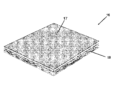
Fig. "1 is a perspective view of a thermo-acoustic barrier in flat sheet form
that
embodies principles of the invention.
Fig. 2 is a side etevational view of the barrier of Fig. I showing the layered
construction of the barrier.
3
CA 03094813 2020-09-18
WO 2019/182561
PCT/US2018/023226
Fig. 3 is a perspective view of the therrno-acoustic barrier as seen from the
opposite
side.
Fig. 4 is a photograph of a test device designed to test the cold formability
of the
thermal barrier material of the thermo-acoustic barrier.
Fig. 5 is a photograph of a cup-shaped piece of the thermal barrier material
formed
according to the method of Fig. 3 and following heat and breakage test.
Fig. 6 is a photograph showing the side-by-side testing of a prior art thermal
barrier
and a thermal barrier of the present invention for smoke and offensive odor
emissions when
heated.
Fig. 7 is a chart showing results of the smoke and offensive odor test shown
in Fig. 5.
Fig. 8 is a photograph showing the side-by-side testing of a prior art thermal
barrier
and a thermal barrier of the present invention for flame ignition point when
heated.
Fig. 9 shows charts and associated graphs illustrating the results of side-by-
side
testing of a prior art thermal barrier and a thermal barrier of the present
invention for thermal
conductivity (thermal mapping).
Fig. 10 is a chart showing results of the side-by-side testing of a prior art
thermal
barrier and a thermal barrier of the present invention for toxicity of gasses
generated when
heated.
Fig. 11 is a summary chart compiling the results of various tests conducted on
the
TI1000 thermal barrier of the present invention and a prior art thermal
barrier with similar
performance specifications.
Fig. 12 is a summary chart compiling the results of various tests conducted on
the
TI650 thermal barrier of the present invention and a prior art thermal barrier
with similar
performance specifications.
4
CA 03094813 2020-09-18
WO 2019/182561
PCT/US2018/023226
DETAILED DESCRIPTION
Reference will now be made in more detail to the drawing figures, wherein like
reference numerals indicate like parts throughout the several views. Fig. 1
illustrates a
thermo-acoustic barrier that embodies principles of the invention in one
preferred form. The
thermo-acoustic barrier 16 comprises a high temperature thermal barrier layer
17 bonded to
an acoustic absorption layer 18. The term "high temperature" as used herein
means
temperatures encountered adjacent hot surfaces of modem engines and exhaust
systems.
Such temperatures generally range from between 650 C and 10002 C 112' F and
1832'
F) but can be somewhat lower or higher in specific cases. The high temperature
thermal
barrier layer 17 is formulated and fabricated as detailed below to withstand
high
temperatures while generating very low (compared to the prior art) smoke and
very low odor
intensity and offensiveness.
An acoustic absorption layer 18 is secured to the thermal barrier layer 17 on
one side
thereof. The acoustic absorption layer 18 can be secured to the thermal
barrier layer by any
1.5 appropriate means such as with an adhesive for example. One preferred
method of
securing the layers together is shown in Figs. 2 and 3. Fig. 2 shows the
thermo-acoustic
barrier 16 with the acoustic absorption layer facing up and Fig. 3 shows a
cross section of
the thermo-acoustic barrier. In this embodiment, the acoustic absorption layer
18 is punched
to form a plurality of holes 19 that extend through the acoustic absorption
layer.
The thermal barrier layer 17 is initially applied in the form of a slurry onto
an upwardly
facing surface of the acoustic absorption layer 18. The slurry flows partially
into the holes 19
as perhaps best illustrated in Fig. 2. As the slurry is dewatered and dried,
preferably using a
Fourdrinier or other type of paper making machine, the thermal barrier
material in the holes
19 dries and locks the thermal barrier layer 18 and the acoustic absorption
layer 17 together
with a mechanical bond.
The acoustic absorption layer 18 may be formed of any material that performs
the
function of absorbing sound before it enters the passenger compartment of a
vehicle. In the
preferred embodiment, the acoustic absorption layer 18 is made of a non-woven
fiberglass
5
CA 03094813 2020-09-18
WO 2019/182561
PCT/US2018/023226
sound absorbing material such as that available from Owens Corning Corporation
of Toledo,
Ohio and other suppliers. Other possible materials that may be suitable for
the acoustic
absorption layer include, without limitation, cotton and organic sound
absorbing batts, silica
fiber mats, and sound absorbing foam to mention a few.
$ While the thermo-acoustic barrier is shown as a flat sheet or tile in
Figs. 1 and 2, it
should be understood that in use the barrier often will be shaped to fit in a
specific tight
space between a hot surface such as a catalytic converter and the floor panels
of a vehicle.
Furthermore, the thermo-acoustic panel may be adhered to one side of a shaped
aluminized
metal sheet or sandwiched between two metal sheets that can be pressed into a
desired
1.0 shape and also serve as thermal reflectors. So, the flat sheet or tile
shown in the illustrative
embodiment is not intended to limit the invention, but only to illustrate the
layered
construction of the barrier in a simple and easily understood form.
As detailed below, it has been found through experimentation that the smoke
and
unpleasant odors often produced by prior art thermal barriers (of which
consumers complain)
15 result from the bum-off of organic binders and other organic compounds
present in the
material of these barriers. In contrast, the materials from which the thermal
barrier of the
present invention is made are very low in organic compounds and binders
compared to prior
art thermal barriers. In one preferred embodiment: the thermal barrier of this
invention may
be made as follows.
MAKING THE THERMAL BARRIER
Table I below shows the ingredients used to make the thermal barrier of the
present
invention and, for each ingredient, the percent-by-weight of the ingredient
used in a slurry to
be made into the thermal barrier in a paper making machine.
6
LY10001
TI650 TI1K
magnesium silicate 17-23 8-12
aluminum phyllosilicate clay 2-5 2-5
hydrous aluminum silicate 17-23 8-12
hydrous magnesium silicate 12-18 12-18
phyllosilicate (mica) 4-7 4-7
alumina trihydrate 17-23 35-43
alumino-borosilicate glass 2-6 2-6
dye 1-1.5 .5-1.5
rock wool 6-8 6-8.5
basalt fiber 1-6 4-7
acrylamide copolymer coagulant .05-1.5 .05-1.5
acrylic latex .07-1.2 .05-.95
fatty alcohol alkoxAate .01-.05 .01-.05
anionic polyacrylamide .5-1.5 .5-1.5
cellulose fiber 1-1.8 0
Table 1
Except for the basalt fibers, the fibers and clays in Table 1 are combined
with water
(between 7 and 50 C) into a slurry using a pulper. To maintain the length of
the basalt
fibers, they are added directly to the mixing chest and homogenized into the
mixing stock to
avoid the shear forces generated in the pulper. The latex is then added and
precipitated
onto the fiber and fillers. The resulting slurry is spread onto the conveyor
belt at the wet end
of a traditional Fourdrinier paper making machine forming a wet web of fibers,
If the thermal
barrier is to be combined with an acoustic absorption barrier, the slurry may
be spread onto
a thin sheet of the acoustic absorption material, which may have been prepared
with holes to
facilitate binding the two layers together. In the machine, the wet web is
dewatered and
dried. The resulting web can then be cut into desired shapes and molded if
desired to fit into
areas where it is to be used.
7
Date Recue/Date Received 2022-04-11
LY10001
TESTING
Most of the tests described below were carried out according to the
corresponding
established industry method (typically an ASTM standard). However, due to the
subjective
nature of the offensive odor testing, internal testing methods were developed
that quantified
the intensity and offensiveness of odors produced by prior art thermal barrier
materials and
by thermal barrier materials of the present invention. An objective test for
the presence of
chemicals known to produce offensive odors also was carried out. In addition,
the thermal
masking tests were conducted using an internal testing method historically
used to assess
various thermal conduction properties of heat shield insulating material.
These tests are
detailed below.
1. Cold Formability and Vibration Testing
Figs. 4 and 5 illustrate devices used to test the cold formability of thermal
barrier
material made according to the above described process. The test was carried
out
according to test method WI-TP-033_0. Both the TI650 and the TI1000 (TI1K)
embodiments
of the thermal barrier materials were tested. For each material, a circular
sample 23 of the
material was die-cut from a sheet and positioned over a spherical depression
on the anvil of
a press 22. A spherical ram 24 was then pressed onto the sample until the
sample was
urged into the depression, thereby molding the sample into a bowl shaped
configuration.
After each sample was molded into a bowl shape as described, it was heated in
a
furnace to 400 C for 30 minutes and then placed in a tabletop shaker 26 (Fig.
5) for 5
minutes. Flat die cut specimens that had not been molded also were heated and
shaken in
this manner. This test sought to simulate the heat and vibration that might be
experienced
by the material when used in a vehicle. If the sample breaks into several
pieces after
heating and shaking or displays large separations, then it is likely that the
material will crack
or break up during crash forming of a commercial heat shield or during normal
use. As
shown in the summary test results chart of Fig. 11, the test revealed for the
TI650 material
that there were no cracks and the sample was in-tact after heating and
vibration as
8
Date Recue/Date Received 2022-04-11
CA 03094813 2020-09-18
WO 2019/182561
PCT/US2018/023226
described. The 111000 material was observed to exhibit some small cracks, but
the sample
was otherwise in-tact after heating and vibration. The conclusion is that the
therrnal barrier
material of the present invention exhibits acceptable cold formability
properties.
To determine loss of mass due to dusting compared to prior art thermal barrier
$ materials, die-cut and cold formed thermal barrier samples of the present
invention and
samples of prior art thermal barrier materials were tested. In each case, a
sample was
weighed, heated to 400G C for 30 minutes, placed in a table top shaker for 5
minutes, and
then weight again. Any loss in weight is due to dusting of material away from
the sample
during the heating and shaking process. Fig. 5a shows the results of these
tests. As can be
seen, for the three prior art samples tested. total loss of weight due to
dusting (loss from die-
cut sample plus loss from cold formed sample) ranged between 0.65% and 1.04%.
Loss
from the die cut sample was significantly less than loss from the cold formed
sample for
each of these prior art thermal barrier material.
In stark contrast, the total loss of weight due to dusting for the T11000
thermal barrier
sample under the same test conditions was a mere 0.14% with about half of the
loss (.06%)
being due to die-cut sample loss. For the 11650 sample of the present
invention, total loss of
weight was still a mere 0.14% but the great majority of the loss (0.12%) was
due to dusting
losses from the die-cut sample. The cold formed sample lost only 0.02% of its
weight during
the test. The conclusion is that heat barriers formed according to the present
invention
exhibit far less weight loss due to dusting than do the prior art heat
barriers tested.
2. Smoke and Offensive Odor Test
Figs. 6 and 7 illustrate subjective testing of the thermal barrier material of
this
invention for the production of smoke and offensive odor at high temperatures.
As
discussed above, consumer complaints have focused on this unpleasant aspect of
the prior
art. For this test, a lab hot plate 29 was heated to 400 C. A sample of prior
art thermal
barrier material 28 was placed on the hot plate 29 and held down by weights
33. The
material was then observed by members of a panel who focused on odor produced
by the
9
LY10001
sample over time as its temperature rose. Members of the panel rated odors
produced by
the sample for intensity and offensiveness over a 5 minute period. All
responses of the
panel members were then tabulated.
The same test was carried out with a sample of the TI1000 (TI1K) thermal
barrier
sample 29 made according to the present invention and a prior art thermal
barrier with
similar specifications. Again, the pane! members rated the intensity and
offensiveness of
odors produced by the sample just as they had done with the prior art sample
28. The
results of this test are shown in the chart 36 of Fig. 7, which plots the
results of the tests on
a scale of rating vs. time. As can be seen, the intensity of odors produced by
the prior art
thermal barrier material 39 was rated between 4 and 5 from .5 minutes until 2
minutes before
slowly settling at a rating of about 1 after 2.5 minutes. The offensiveness 40
of these odors
was rated even higher at 6 until 2 minutes into the test before slowly falling
to 1 at 4
minutes.
In contrast, the intensity 38,42 of odors produced by the TI1000 (TI1K) and
TI650
samples made according to the present invention rated very low at just above
zero for the
full duration of the test. Offensiveness 37, 41 of these odors for these
samples rated
between 1 and 1.5 at the beginning, ramping down to just above zero at one
minute into the
test. Thus, thermal barriers made according to the present invention showed a
drastic
reduction in intensity and offensiveness of odors produced at high
temperatures compared
to those produced by the prior art thermal barrier.
In addition to these subjective tests, an objective odor evaluation was
commissioned
by an outside laboratory. The laboratory tested liberated gases from a sample
of prior art
thermal barrier material and a sample of thermal barrier material made
according to the
present invention when heated as described above. Gas Chromatography (GC) and
Mass
Spectrometry (MS) techniques were used to determine the presence of 1-butano
and
Dimethoxymethane, both deemed by most humans to be associated with and
indicative of
offensive odors.
Date Recue/Date Received 2022-04-11
LY10001
As can be seen from the summary chart of Fig. 11, the prior art sample was
determined to produce 4.58 parts per million (ppm) of 1-butanol while a sample
of the
present invention produced less than 3 ppm, less than 1 ppm and, in this test,
no detectable
1-butanol. As for Dimethoxymethane, the prior art sample produced 190 ppm
while the
sample of the present invention produced less than 100 ppm, less than 50 ppm
and
specifically 42.6 ppm. Such levels are considered indicative of low levels of
offensive odors
to humans.
Fig. 12 shows the same data for the TI650 thermal barrier sample vs the
comparative
prior art sample. The prior art sample produced 6.14 ppm of 1-butanol while
the TI650
sample produced less than 4 ppm, less than 2 ppm, and in this particular test.
no 1-butanol.
The prior art sample produced 224 ppm Dimethoxymethane while the TI650 sample
of the
present invention produced less than 150 ppm, less than 100 ppm and, in this
particular test,
55 ppm. Such ranges are considered to be indicative of low amounts of
offensive odors.
This objective testing supports the conclusions of the subjective tests that a
thermal barrier
of the present invention produces far less offensive odors when heated than
does the prior
art.
The density of produced smoke for the barriers of the present invention also
was
measured according to the ISO 5659-2:2006(E) standard. The measured density
for both
the TI650 and the TI1000 (TI1K) samples was less than 5 g/cm3, less than 2
g/cm3 and
more specifically measured to be about 0.88 g/cm3. Such smoke densities are
considered
barely detectable. As can be seen in Fig. 6, which shows the prior art sample
28 and the
TI1000 (TI1K) sample 29 side-by-side on a 400 C hotplate 27, the density of
smoke 32
produced by the TI1000 (TI1K) sample 29 is far less than the density of smoke
31 produced
by the prior art sample 28. The conclusion is that the high temperature
thermal barrier
material of the present invention produces negligible smoke when heated to
high
temperatures whereas the prior art produces significant smoke of which
consumers
complain.
11
Date Recue/Date Received 2022-04-11
LY10001
3. Shock Flame Testing
A prior art thermal barrier material and the TI1000 (TI1K) thermal barrier
material of
the present invention were tested to determine their tendency to ignite at
high temperatures.
These two products have similar maximum temperature specifications of 1000 C.
The test
setup is shown in Fig. 8. A furnace 43 was preheated to a temperature of 650
C before
placing a 2 inch by 6 inch prior art sample and a 2 inch by 6 inch sample of
the TI1000
(TI1K) thermal barrier 46 in the furnace. A viewing port in the furnace wall
allowed the flame
point and smoke production, if any, to be visually determined. After a short
time in the
furnace, the prior art thermal barrier sample 44 caught fire 45 as seen in
Fig. 8 and began to
burn. This is considered a catastrophic failure of the barrier. The TI1000
(TI1K) thermal
barrier sample 46 of the present invention did not ignite at 650 C. In fact
TI1000 (TI1K)
thermal barrier 46 was subsequently tested at its design temperature of 1000
C and again
did not ignite or fail.
Similarly, a prior art thermal barrier material and the TI650 thermal barrier
material of
the present invention were tested for ignition using the same procedure. These
two products
have similar maximum temperature specifications of 650 C. Again, the two
samples were
placed in a furnace pre heated to 650 C and observed. As shown in the
photograph of Fig.
12, the prior art sample ignited and failed at this temperature while the
TI650 sample of the
present invention did not.
4. Thermal Mapping Tests
Prior art thermal barriers and thermal barriers of the present invention were
tested to
determine the thermal conductivity of the material. This test is sometimes
referred to as a
thermal mapping test and was carried out according to ASTM standard F433. In
the test, a
sample of interest was placed directly on a pre-heated 400 C hotplate. An
infrared
thermometer was used to map the rise in temperature of the top (exposed) side
of the
sample. The test was conducted for samples of thickness 0.8 mm and 1.0 mm for
each of a
prior art thermal barrier material, the TI650 barrier of the present
invention, and the TI1000
barrier of the present invention. The results are shown in Fig. 7 where the
charts on the right
12
Date Recue/Date Received 2022-04-11
LY10001
shown graphically that the prior art thermal barrier conducted significantly
more heat to its
exposed face than did either the TI650 or the IT1000 samples of the present
invention. This
is true for both the 0.8 and 1.0 mm thicknesses of the samples.
The test results are shown numerically on the left in Fig. 9. For the 0.8 mm
thick
samples, the exposed face of the prior art sample rose to a temperature of 324
C while the
exposed faces of the TI650 and TI1000 samples rose to only 313 C and 304 C
respectively. Similarly for the 1.0 mm thick samples, the exposed face of the
prior art
sample rose to 323 C while the exposed faces of the IT650 and TI1000 samples
rose to
temperatures of 312 C and 289 C respectively. These results demonstrate a
thermal
conductivity (thermal K) for the prior art thermal barrier material of 0.188
while the
conductivity of the thermal barriers of this invention were 0.114 for the
TI650 material and
0.095 for the TI1000 material. The conclusion is that thermal barriers of the
present
invention have significantly lower thermal conductivities than the prior art
and transmit less
heat from one surface to the opposite surface.
5. Toxicity of Generated Gases Test
A sample of prior art thermal barrier material and a sample of the TI1000
(TI1K)
barrier material of the present invention were tested according to ASTM
standard 800
relating to Measurement of Gases Present or Generated During Fires.
Specifically, gasses
produced by these samples when burned were collected and analyzed using
Fourier
Transform Infrared Spectroscopy (FTIR) for toxic compounds contained in the
resulting
smoke. The testing measured the presence of the following compounds: CO; CO2;
HCL;
HCN; HBr; HF; NO; NO2.; and SO2. With the exception of carbon monoxide (CO)
and
carbon dioxide (CO2), none of the toxic compounds were present. As for CO and
CO2
levels in the gasses were determined and are presented in the table of Fig.
10. As can be
seen, the TI1000 (TI1K) thermal barrier material produced more than 8 times
less CO and
more than 13 times less CO2 than the prior art thermal barrier material, a
substantial and
13
Date Recue/Date Received 2022-04-11
LY10001
significant improvement. The sample of the TI1000 (TI1K) thermal barrier
material
produced less than 100 ppm CO gas, less than 50 ppm, and about 46 ppm as
measured
according to ASTM 800 standards. The sample of the TI1000 (TI1K) thermal
barrier
material produced less than 700 ppm of CO2 gas, less than 600 ppm, and about
599 ppm
as measured according to ASTM 800 standards.
13A
Date Recue/Date Received 2022-04-11
CA 03094813 2020-09-18
WO 2019/182561
PCT/US2018/023226
6. Summary of Testing
Fig. 11 presents a table comparing results of the above described testing and
other
tests for a sample of the T11000 thermal barrier material. Also shown are the
results of the
$ same tests for a sample of prior art thermal barrier material with
similar performance
specifications. Results for the prior art sample are shown in column 4 while
results for the
T11000 sample of the present invention are shown in column 5. First, the
caliper (thickness)
and density of each sample was measured using the indicated ASTM standards.
The
Caliper of the prior art sample was determined to be 0.80 mm and its density
was
.. determined to be 1.15 gicm3. This compares to the T11000 sample of the
present invention,
which had a caliper of 0.857 mm and a density of 0.90 worn, The two samples
were very
similar in thickness and density.
A horizontal flame spread test was conducted on the two samples according to
SAE
J369 testing standards. In this test, each sample was suspended in a
horizontal orientation
1.5 .. and a Bunsen burner was placed beneath one end of the sample. If the
sample ignited and
the flame did not self-extinguish, a rate at which the flame was observed to
spread would be
tabulated. In this test, the prior art sample did not ignite (DN1) and the
sample of the T11000
thermal barrier also did not ignite.
A compression/recovery test was conducted on both samples according to ASTM
F36K standards using an Armstrong Static Indentation Machine. This test
measures the
ability of the material to absorb compressive forces and, once compressed, how
well the
material returns to its original caliper. The thickness of the sample is
measured and then the
sample is subjected to an extreme load for a specified time sufficient to
compress the
material. The load is then removed and the material is allowed to rebound
partially to its
original thickness. The final thickness is then measured. The rebounded
thickness divided
by the original thickness represents the compression/rebound measurement
expressed as a
percentage. Greater rebound is desirable. in these tests, the prior art sample
rebounded by
16/28 or 57% while the sample of the present invention rebounded by 20/27 or
74%. Thus,
14
CA 03094813 2020-09-18
WO 2019/182561
PCT/US2018/023226
a thermal barrier of the present invention is more tolerant of Compressive
loads than the
thermal barrier of the prior art.
The thermal conductivity of each sample was measured according to the
procedure
outlined above. The results are tabulated again in the summary chart of Fig.
11.
$ Fig. 12 presents a table comparing results of the above described testing
and other
tests for a sample of the T1650 thermal barrier material. Also shown are the
results of the
same tests for a sample of prior art thermal barrier material with similar
performance
specifications. As with tests for the T11000 sample, results for the prior art
sample are
shown in column 4 while results for the T1650 sample of the present invention
are shown in
column 5. As can be seen from Fig.12, the T1650 sample made according to the
present
invention performed significantly better than the prior art sample in
virtually every test.
The invention has been described herein in terms of example embodiments
considered by the inventor to represent the best modes of carrying out the
invention. It will
be understood by one of skill in the art, however, that a wide gamut of
additions, deletions,
and modifications, both subtle and gross, can be made to the illustrative
embodiments
without departing from the spirit and scope of the invention, which is
delineated only by the
claims.