Note: Descriptions are shown in the official language in which they were submitted.
CA 03095110 2020-09-24
1
Method for machining at least one switchgear cabinet
The invention relates to a method for machining at least one switch cabinet.
The method
comprises providing of at least one switchgear cabinet which is constructed in
several
parts and has at least one detachably mounted component. For example, an
electrical
cabinet usually has an electrical cabinet frame with flat panels attached
thereto, for
example side walls, a door element, a roof element, and a mounting plate
mounted in
the electrical cabinet. The flat panels and the mounting plate are usually
detachably
connected to the frame, e.g. by screw connections, whereby the frame forms the
supporting structure of the switch cabinet. Such a switch cabinet, consisting
of a frame,
flat panels attached to it and a mounting plate mounted inside the switch
cabinet, is a
common high volume product of a switch cabinet manufacturer.
Switch cabinets are used to accommodate switchgear, which can be designed very
differently depending on the application and can therefore also have different
requirements for the structure of the switch cabinet. For example, depending
on the type
of switchgear, the switchgear must be cooled. For this purpose, for example,
an opening
must be formed in a side wall of the switchgear cabinet housing through which
a cooling
unit mounted on or in the side wall draws heated air from the switchgear
cabinet
housing and blows it back into the switchgear cabinet housing as cooled air.
If the
switch cabinet is to be used in a data center, for example, it may be intended
that the
switch cabinet is to be placed in a row of switch cabinets of the same type,
whereby the
switch cabinets of the row are not only mechanically connected to each other,
but also
often form a continuous assembly space that spans several switch cabinets and
is used
for the arrangement of server racks and the like, for example. For example, it
is
common practice that a power supply for the switchgear cabinet row is provided
via a
continuous busbar arrangement that extends through all the switchgear cabinets
of the
switchgear cabinet row in order to provide a power supply for the electrical
and/or
electronic components of an electrical switchgear system that are accommodated
in the
respective switch cabinets. Although an IT-infrastructure is not an electrical
switchgear
according to the linguistic usage, it shall be covered by the term electrical
switchgear in
order to simplify the representation of the invention.
Date Recue/Date Received 2020-09-24
CA 03095110 2020-09-24
2
As a consequence, the switchgear cabinet provided by the switchgear cabinet
manufacturer as a standard product has to be subjected to a considerable
individualization until its actual use by the end user, and this concerns both
the
mechanical condition of the switchgear cabinet and the switchgear incorporated
in the
switchgear cabinet. This has led to the fact that in the value-added chain
between the
switch cabinet manufacturer and the end user of the switch cabinet housing,
for
example a machine builder, who controls a machine with the help of the
switchgear
accommodated in the switch cabinet, a branch of industry has formed around the
switch
cabinet construction, which is specialized in obtaining standardized series
switch
cabinets from the switch cabinet manufacturer, equipping them with the
switchgear
required by the end customer and thereby individualizing the switch cabinet to
the
extent required in each case by mechanical, mostly machining finishing.
This individualization is often associated with the fact that the at least one
removable
and post-processed component of the switch cabinet, for example a flat panel
or a
mounting plate, is disassembled from the switch cabinet, preferably from the
switch
cabinet frame, and removed from the switch cabinet in order to feed the
component to a
machining station for individualization, for example to make openings or
threaded
passages in the flat panel or mounting plate.
The mounting plate is also removed from the switchgear cabinet for equipping
the
mounting plate with the switchgear and is manually or automatically provided
with the
electrical and/or electronic components of the electrical switchgear,
including wiring of
the components and functional testing of the switchgear. Thus at least one
machining
step of the detachably mounted component takes place when it has been
disassembled
and removed from the switch cabinet. The processed component is then made
available
for reassembly on the associated switchgear cabinet. In order to enable a
reassignment
of the processed component provided for reassembly exactly to the
corresponding
switch cabinet, it has been common practice so far to temporarily mark the
removable
components and the switch cabinet, e.g. by means of manually applied markings.
This
is accordingly cumbersome and error-prone.
It is therefore the object of the invention to provide a method for the
machining of at
least one switch cabinet which is easy to perform and not prone to errors.
Date Recue/Date Received 2020-09-24
3
This object is solved by a method with the features as described below.
Accordingly, it is provided that the at least one switch cabinet has an
individual
machine-readable switch cabinet identification and the at least one removably
mounted
component has an individual machine-readable component identification which
are
assigned to each other, wherein the re-assignment of the component to the
switch
cabinet comprises the machine-reading of the machine-readable identifications
and the
bringing together of the component and the switch cabinet which have the
mutually
assigned identifications.
For example, at least two identical switch cabinets can be provided during
provision, for
example two switch cabinets that correspond to the standard product of a
specific article
number of a switch cabinet manufacturer. The two switch cabinets will
therefore not
differ from each other in their characteristics. In particular, the two switch
cabinets may
have a switch cabinet frame with flat panels fixed to it. The frames of the
two switch
cabinets, as well as the mounting plates and flat panels will therefore not
differ from
each other. At least one of the aforementioned detachably mounted components
of the
switchgear cabinet may have the switchgear cabinet identification, if
necessary in
addition to a component identification, if the component having the switchgear
cabinet
identification is a component detachably mounted on the switchgear cabinet,
for
example a flat panel, such as the switchgear cabinet door. Thus, each of the
two series
switch cabinets supplied by the switch cabinet manufacturer may have a
component
which has at least the switch cabinet identification. At least one component
of the other
components detachably mounted on the respective switch cabinet can have a
component identification which is assigned to the respective switch cabinet
identification.
It may also be provided that a frame of the respective switch cabinet does not
have a
component identification, since the frame is not processed and therefore, in
case of a
plurality of switch cabinets, an individual assignment of a certain frame to a
certain
switch cabinet, i.e. a certain switch cabinet identification, is not
necessary. For
consistency reasons, however, it is conceivable that the switch cabinet frame
also has a
component identification that is assigned to the switch cabinet
identification.
Date Recue/Date Received 2022-02-04
CA 03095110 2020-09-24
4
The component of the switch cabinet which has the switch cabinet
identification, to
which the different removable mounted components of the switch cabinet are
assigned
by their respective component identification, thus has the function of a
reference
component or a master component of a certain switch cabinet, to which certain
further
removable mounted components of the certain switch cabinet are assigned by
their
respective component identification.
In this way it is possible that in the case of several identical switchgear
cabinets, after
dismantling the removably mounted components and, if necessary, after
machining at
least one of the disassembled components, those components which were
originally
provided before the reworking are reassembled at the same switchgear cabinet.
Especially in the case of highly individually reworked switchgear cabinet
components,
such as flat panels of the switchgear cabinet, the previously described
assignment
ensures that after the machining of the disassembled components and the re-
assignment of the processed components to the corresponding switchgear
cabinet,
exactly the components that formed the switchgear cabinet before the
disassembly are
actually reassembled.
Providing of the at least one switchgear cabinet can include the manufacturing
of the
switchgear cabinet, whereby during the manufacturing of the switchgear cabinet
the
removably mounted component of the switchgear cabinet with the component
identification and the at least one further component of the switchgear
cabinet with the
switchgear cabinet identification are manufactured independently of each other
and
after their manufacture are assigned to each other for the first time by
reading in the
identifications.
The provision or the disassembly and removal of the removably mounted
component of
the switch cabinet may involve the generation of a first data set describing a
target
machining state of the component, the first data set being assigned to the
component
via the component identification, and the storage of the first data set for
remote access.
In this way, it is also possible, for example, for the switchgear cabinet
manufacturer to
carry out individualization measures on the series product as early as the
switchgear
cabinet production stage, such as forming cut-outs in flat panels or in the
mounting
plate.
Date Recue/Date Received 2020-09-24
,
CA 03095110 2020-09-24
It is possible that the first data set describing the target machining state
of the
component is already transmitted to the switch cabinet manufacturer before the
switch
cabinet is manufactured, or during this process, for example by a switch
cabinet
manufacturer. Similarly, the target machining state can be transmitted in the
form of a
CAD design from the panel builder to the switch cabinet manufacturer, who
generates
the first data set from it and assigns it to the component identification of
the component
during the manufacture of the detachably mounted component. It may also be
provided,
for example, that a panel builder transmits a CAD design to the switchgear
cabinet
manufacturer which concerns at least the mechanical reworking of the series
switchgear
cabinet, for example the formation of at least one opening in at least one
flat panel of
the switchgear cabinet. The switchgear cabinet manufacturer can then generate
from
the CAD design relating to the post-processing of the switchgear cabinet a
first data set
for each of the components of the switchgear cabinet affected by the post-
processing,
or a common data set describing the target machining state of the component
concerned, the respective first data set then being assigned to the respective
component by means of the respective component identification, for example as
soon
as the respective component concerned has been manufactured in the raw
production
of the components of the switchgear cabinet and has been provided with the
component
identification individually identifying the component. It is thus possible
that already in the
earliest possible manufacturing process of the switch cabinet the individual
components
of the switch cabinet are assigned the information concerning the post-
processing of the
respective component via the link with the component identification. The
control cabinet
component can thus already be highly individualized in the raw production
process,
even if only by assigning a data set relating to the component to the
component.
It is possible, for example, that the components of the control cabinet to be
reworked
compared to the series product may undergo individual reworking before they
are first
assembled to form a control cabinet, so that the control cabinet product
delivered by the
control cabinet manufacturer to the switchgear manufacturer exhibits a certain
degree of
individualization compared to the series product, for example in the form of
cut-outs in
flat panels.
But even in series production, the identification of the switch cabinet and
the at least
one removable component in accordance with the invention can have advantages,
for
example by specifying at least one manufacturing step relating to the
component via the
data set assigned to the component identification, for example an intended
painting of
Date Recue/Date Received 2020-09-24
CA 03095110 2020-09-24
6
the component, an intended foaming to form a sealing element, an intended
sealing
function for attachment in the final assembly and the like.
The generation of the first data set describing the target machining state can
include the
storage of at least one machining step in the first data set, which is
required to transfer
the component from its actual state to the target machining state. The target
machining
state may differ from a final machining state.
Panel fabrication may include the fabrication of the removable mounted
component in
volume production, but the method may still have the steps:
- Capturing the component identification of the removable mounted component in
volume production;
- reading the first data set and detecting the target machining state or at
least one
machining step;
- separating the detachably mounted component from the series production and
feeding
the detachably mounted component to a machining station, wherein in the
machining
station the at least one machining step and/or a further machining step is
carried out to
bring the detachably mounted component closer to the target machining state;
and
- after the machining step has been carried out, reintegration of the
detachably mounted
component into the series production.
If the production of the switch cabinet comprises the production of the
detachably
mounted component in series production, wherein the detachably mounted
component
can pass through several machining stations, the component identification of
the
detachably mounted component can be read out at at least one machining
station, the
first data set assigned to the component identification can be recorded,
taking into
account the first data set and a CAD construction possibly contained therein,
at least
one machining step can be carried out in order to at least approximate the
component to
the target machining state. An updated machining state can be stored in the
first data
set and the first data set for remote access.
Date Recue/Date Received 2020-09-24
CA 03095110 2020-09-24
7
Thus, the method can also include a documentation of performed machining steps
in
the first data set. The first data set can thus reflect the current machining
state of the
component in question during the production of the component between different
machining stations. This ensures that the first data set can be used to
monitor the
expected machining success of the removably mounted component at any time
during
production, i.e. an approximation to the target machining state.
The first data set may contain mechanical design information of a hole pattern
for
machining the detachably mounted component, such as a mounting plate or a flat
panel,
for example for a switchgear to be produced on the mounting plate or for the
mounting
of a switch cabinet air conditioner in or on a flat panel. The design
information can be
provided as CAD data, for example. Manufacturing the removable mounted
component
may involve mechanical machining of the removable mounted component, including
lasers, to produce the hole pattern. For example, the assembled component may
be a
mounting plate that has a hole pattern to form the electrical switchgear on
the mounting
plate. The mounted component can be, for example, a side wall of the
switchgear
cabinet into which a hole pattern is inserted in order to mount a switchgear
cabinet air
conditioning unit on or in the side wall of the switchgear cabinet and to
connect it
fiuidically with the interior of the switchgear cabinet.
Furthermore, the method can include the generation of a second data set, which
is
assigned to the switch cabinet via the switch cabinet identification and
stored for remote
access, whereby the second data set includes a circuit diagram of a switchgear
to be
created or already created in the switch cabinet. The second data set can be
generated
from the first data set, for example by enriching the data concerning the
circuit diagram.
The unique identification of the control cabinet makes it possible to
establish a clear
assignment between a control cabinet and a switchgear to be created or already
created in the control cabinet. Before the switchgear is created in the
switchgear
cabinet, the switchgear to be created in the "empty" switchgear cabinet can
thus already
be assigned to the switchgear to be created in it, at least in the form of a
circuit diagram
describing the switchgear and, if necessary, further information, such as a
component
parts list. This considerably simplifies the logistics of the switchgear
manufacturer, who
has to subject the switchgear cabinet to various post-processing operations at
different
machining stations of his production line in order to manufacture the
switchgear.
Date Recue/Date Received 2020-09-24
CA 03095110 2020-09-24
8
Since the electrical switchgear is permanently assigned to the switch cabinet
in which it
is installed after its construction, due to the high degree of
individualization of the switch
cabinet, a clear identification of the switchgear can be made by means of the
switch
cabinet identification of the switch cabinet in which it is installed.
For example, a second data set assigned to the switch cabinet identification
can be
generated, which contains a circuit diagram of the switchgear accommodated in
the
switch cabinet. Alternatively, the second data set can contain further
information
concerning the switchgear, for example a component parts list, a maintenance
plan or
similar. This also makes it possible that in the event of a change to the
switchgear or in
the event of maintenance, appropriate measures, which may also include a
corresponding adaptation of the circuit diagram, are documented in the second
data set
and stored for remote access. It is therefore no longer necessary to keep a
paper circuit
diagram and a paper maintenance history. Due to the fixed assignment between
switch
cabinet labeling and switchgear, confusion between the circuit diagram and the
actual
switchgear and the loss of the circuit diagram, which is quite possible with
paper
documentation, is also prevented. The second data set can be obtained from the
first
data set by modifying, in particular by enriching the first data set.
The method can also include changing the circuit diagram according to a
recorded
change of the switchgear and updating the second data set so that the updated
second
data set contains the modified circuit diagram. The recording of a change to a
switchgear can be done manually via a human-machine interface or, for example,
partially automated, for example with optical or component recognition.
in the case of semi-automated detection, it may be provided that all
components of the
electrical switchgear, or at least some of the electrical components of the
switchgear,
have individual component identification. This marking should preferably be
contactiess
and preferably optically readable and can be provided in the form of a QR
code, for
example, but is not limited to QR codes. With the help of such a detection,
e.g. optical
detection, it can be determined which components the switchgear has, at least
to the
extent that the components are provided with a component identification. The
second
data set may, for example, contain a list of components of the switchgear
which can be
updated on the basis of the recorded components if, for example, a change in
the
component population of the switchgear occurs during a revision of the
switchgear or
=
Date Recue/Date Received 2020-09-24
CA 03095110 2020-09-24
9
during maintenance. For example, it may be intended that the recording of a
change in
the switchgear includes the recording of the component identifications of the
components of the electrical switchgear, whereby a change in the component
equipment of the electrical switchgear can be recorded by comparing the
recorded
component identifications with the circuit diagram.
With the help of the component identification, however, a recording of the
relative
arrangement of the components to each other is basically also possible beyond
the
provision of a parts list. For this purpose, it may be provided that the
method comprises
the at least partial optical or electromagnetic detection of an interior of
the switchgear
cabinet, in particular of a mounting side of a mounting plate on which the
electrical
switchgear is arranged, wherein the detection comprises the detection of at
least one
component identification of at least one component of the switchgear, wherein
the
detection comprises, in addition to the detection of the component
identification, further
the detection of a location information of the component relative to at least
one further
component of the switchgear with a further component identification.
Furthermore, the
acquisition can include the acquisition of a correct positioning of at least
one component
of the switchgear. This can include the alignment of a 2D or 3D layout with
the acquired
location information. The acquisition can also include the acquisition of the
completeness of the electrical switchgear. A component list can be compared
with the
captured components.
The electrical components of the switchgear with the component identification
can also
include the wiring of the electrical switchgear. For example, a wire routed
between a first
and a second component and electrically connecting them may have a component
identification at its opposite ends, with which it is connected to the first
component or to
the second component, so that the method can also be used to compare the
wiring of
the components and, if necessary, to compare the detected wiring with a wiring
stored
in a circuit diagram and, if necessary, to document a deviation or change. The
circuit
diagram can in turn be stored as a data set for remote access via the switch
cabinet
identification or also via a component identification of the mounting plate on
which the
switchgear described by the circuit diagram is formed.
The method can further include the creation of an electrical switchgear in the
switch
cabinet, starting from a CAD design of the switchgear, which is assigned to
the switch
Date Recue/Date Received 2020-09-24
CA 03095110 2020-09-24
cabinet via the switch cabinet identification, whereby data sheet information
of electrical
components of the electricai switchgear is linked with information about their
interconnection in the electrical switchgear and is stored in a central
archive database
under the switch cabinet identification in at least one data set.
The method can also include the technical approve of the switchgear, whereby
test and
approval information of the switchgear is added to the at least one data set.
If the
required test and approval information is complete, a commissioning release
for the
switchgear can be triggered. The switchgear can then be commissioned, whereby
commissioning information of the switchgear is added to the at least one data
set,
preferably via a human-machine interface.
The switchgear cabinet identification can thus be used during the various
stages of the
construction of a switchgear and even already during the manufacture of the
switchgear
cabinet that will house the switchgear in the future to allocate the measures
required
with the construction and commissioning of the switchgear to each other. In
principle, it
is possible to produce a complete design of the switchgear and the switchgear
cabinet
containing it, including information on the technical acceptance of the
switchgear and
the commissioning of the switchgear, before the switchgear cabinet is
manufactured
and before the switchgear is built, using suitable design tools such as MCAD
and ECAD
tools. This complete design of the switchgear can be assigned to a specific
switchgear
cabinet and its components by means of the unique switchgear cabinet
identification
and the component identifications linked to it, so that at each stage of the
switchgear
cabinet or switchgear, from manufacture through operation to disposal, the
information
required in each case from the bundle of information assigned to the
identifications can
=
be retrieved by the respective shareholder.
In this way, the method can continue to include the performance of maintenance
or
repair of the switchgear after commissioning of the switchgear as well as the
addition of
maintenance information or repair information to at least one data set stored
in the
archive database. The method can also include the execution of a switchgear
repair,
whereby a three-dimensional CAD design of the switchgear is used.
The triggering of a commissioning release can include the connection of at
least one
energy source to the switchgear and/or at least one connection from the
switchgear
Date Recue/Date Received 2020-09-24
CA 03095110 2020-09-24
11
cabinet to the switchgear to activate it. If commissioning is carried out
after the
switchgear has been given commissioning release, the at least one data set in
the
archive database can be further enriched with supplementary commissioning
information of the electrical switchgear.
It is thus possible to create a documentation already at the time of the
manufacturing of
the electrical switchgear, which offers a higher depth of information than a
usual
switchgear cabinet folder in paper form, by not only reproducing the
components
installed in the switchgear, but also implementing their data sheet
information in the
documentation. In addition, function information linked to this can provide
information
about the function of a specific electrical component of the switchgear in its
respective
installation situation in the concrete electrical switchgear, for example the
control of a
frequency converter for a three-phase motor of a pump or similar.
All information concerning the switchgear can be carried along and dynamically
updated
over the entire product life cycle of the switchgear and the switch cabinet in
which the
switchgear is installed.
The method can also include the reading of the switchgear cabinet
identification and the
provision of a CAD design of an electrical switchgear to be formed in the
switchgear
cabinet, whereby the CAD design is assigned to the switchgear cabinet via the
switchgear cabinet identification. The method can also include the import of
the CAD
design into a computer-aided assistance unit. The computer-aided assistance
unit can
be set up to fragment the CAD design. The CAD design can be broken down into
individual assembly steps that build on each other in order to determine an
efficient
assembly step sequence of the electrical switchgear, for example on a mounting
plate of
the switchgear cabinet.
The assembly step sequence can include at least two consecutive wiring steps
of two
components of the electrical switchgear or at least two consecutive component
positioning steps of two components of the electrical switchgear.
The computer-aided assistance unit can be set up to break down the CAD design,
which has at least a three-dimensional layout and a parts list of the
individual electrical
Date Recue/Date Received 2020-09-24
CA 03095110 2020-09-24
12
components of the electrical switchgear, into individual assembly steps that
build on
each other.
The computer-aided assistance unit can have a tolerance evaluation device for
step
sequence control, with the help of which sensor-registered actual installation
positions
of mounted components of the switchgear can be compared with target
specifications
according to the circuit diagram, taking into account specified installation
tolerances.
The sensoric acquisition of the actual installation positions can be done
optically and
with the help of image processing. For easier recognition of the components by
the
computer-aided assistance unit, the components of the electrical switchgear
can each
have a component identification, so that each component marked with the
component
identification can be clearly distinguished from the other components.
Furthermore, the method can also include the visualization of a manually
executable
assembly step of the assembly step sequence by a display unit installed at an
assembly
site, which outputs image and/or text information as assembly instructions.
The method
may further include the execution of the manually executable assembly step
according
to the displayed image and/or text information. Furthermore, the method may
include
the acknowledgement of the completed assembly step via an input unit installed
at the
assembly site and the logging of the completion of the assembly step as well
as the
retrieval of a next assembly step of the assembly step sequence. At the latest
after
completion of all assembly steps of the assembly step sequence, a protocol
data set
assigned to the switch cabinet identification can be generated and stored for
remote
access, which has a protocol of the completed assembly steps of the assembly
step
sequence.
Furthermore, the method can include the configuration of an electrical
switchgear for the
switch cabinet, which is at least composed of several electrical and/or
electronic
components. The configuration may include the creation of an electrical
circuit diagram
of the electrical switchgear or, if already existing, the provision of the
electrical circuit
diagram.
Furthermore, the method may include the conversion of the electrical circuit
diagram
into a three-dimensional assembly layout of the switchgear cabinet interior,
in particular
Date Recue/Date Received 2020-09-24
CA 03095110 2020-09-24
13
into a three-dimensional mounting plate layout representing an arrangement of
the
electrical and/or electronic components on a mounting plate of the switchgear
cabinet.
Furthermore, the method can comprise the modification of the three-dimensional
layout
to generate at least one alternative three-dimensional layout, wherein a
quality function
is applied which takes an extremum if the electrical switchgear is optimized
with respect
to a physical parameter, preferably with respect to a packing density of the
electrical
and/or electronic components of the switchgear, a thermal load of the
switchgear, an
electrical energy consumption of the switchgear, at least one cable length for
the wiring
of the electrical and/or electronic components of the switchgear.
Furthermore, the method may include the generation of a third data set
representing the
alternative three-dimensional layout, the assignment of the switchgear cabinet
identification to the third data set and the storage of the third data set for
remote access.
For the modification of the created three-dimensional layout into the
alternative three-
dimensional layout, a modification algorithm can be applied, which applies the
quality
function. The quality function represents the goal, which is to be achieved
with the
modification, for example the increase of the space utilization ratio of the
electrical
switchgear. If several goals are to be achieved simultaneously, compromises in
the
sense of a lowest common denominator can be found in case of conflicting
goals.
Instead of the quality function, it is also possible to specify boundary
conditions that
must be precisely maintained, for example a maximum temperature or maximum
energy
consumption of the electrical switchgear.
When disassembling and removing the at least one component from at least one
switchgear cabinet, at least two components designed as identical parts can be
disassembled and removed, which differ in at least one feature after
machining.
The component identifications of the at least two components designed as
identical
parts may furthermore each be assigned to a unique and different local feature
comprising an assembly position of the respective component on the switch
cabinet, the
re-assignment of the machined components further comprising an assignment of
the
machined components to their respective assembly position on the switch
cabinet.
Date Recue/Date Received 2020-09-24
CA 03095110 2020-09-24
14
During the disassembly and removal of the component from the respectively
associated
cabinet, at least two identical or nearly identical components of different
cabinets can be
disassembled and removed.
When machining the identical or almost identical components, the components
can be
processed differently, so that the components differ in at least one feature
after
machining.
The reading of at least one of the characteristics may involve the reading of
an optically
readable identification, in particular a barcode or a multidimensional code,
such as a QR
code, and/or the reading of an electromagnetic, inductive or capacitive
readable
identification, in particular an RFID transponder
Providing of the at least one switchgear cabinet may include the manufacture
of the
switchgear cabinet, at least one of the components being a shaped sheet metal
part
formed from a steel sheet blank by shaping and, if necessary, machining and/or
further
sheet metal working measures and, if necessary, subsequent painting. Before
painting,
the sheet metal shaped part may be provided with the machine-readable
identification
which is overpainted during the painting of the sheet metal shaped part so
that the
surface of the sheet metal shaped part and the component identification are
covered
with an uninterrupted paint layer.
Providing of the at least one switchgear cabinet may include the manufacture
of the
switchgear cabinet, at least one of the components being a formed sheet metal
part
which is formed from a steel sheet blank by shaping and, if necessary,
machining
measures, the machine-readable identification being printed on the formed
sheet metal
part with a color which is visible or invisible in the optical wavelength
range.
Providing of the at least one switchgear cabinet can comprise the manufacture
of the
switchgear cabinet, wherein at least one of the components is a sheet metal
shaped
part which is formed from a steel sheet blank by shaping and optionally
machining
measures and optionally a subsequent lacquering, wherein a phase change
material or
a matrix of individual fields of a phase change material is applied to the
sheet metal
shaped part or optionally to the lacquering and optionally lacquered over with
the
lacquering of the sheet metal shaped part, wherein the phase change material
or the
Date Recue/Date Received 2020-09-24
¨
CA 03095110 2020-09-24
matrix is described by thermal and/or electrical action to form the
identification with the
at least one feature.
Furthermore, an accessory component can be mounted on or in the at least one
switch
cabinet, which has a unique accessory identification which is assigned to the
switch
cabinet identification, wherein the accessory identification is assigned to
the switch
cabinet identification before, after or during the mounting of the accessory
component
on or in the switch cabinet. The accessory identification can be assigned a
data set
containing installation information of the accessory component, e.g. an
installation
location of the accessory identification in the switch cabinet.
The method may include providing of at least two identical components to be
mounted
in or on the switch cabinet, each with a component identification, whereby the
component identifications of the identical components are assigned an
individual
location feature for differentiation from one another when the respective
component is
mounted in or on the switch cabinet.
The method can comprise the generation of a fourth data set which is assigned
to the
switch cabinet via the switch cabinet identification, the data set comprising
information
concerning the use of the switch cabinet, the maintenance of the switchgear
accommodated in the switch cabinet and/or the intended disposal of the switch
cabinet,
which is taken during manufacture from the planning data stored in the
database and
stored in the identifiers, and/or which is added to the identifiers or updated
in them as
required over the life cycle of the switch cabinet.
Providing can comprise the provision of a switch cabinet with a frame and at
least one
flat panel, whereby the frame and/or the flat panel has an electrical contact.
The
electrical contact can have a protective cover with a non-volatile memory in
which at
least one data set relating to the frame or flat panel having the electrical
contact is
stored, preferably a component identification which uniquely identifies the
frame or flat
panel having the electrical contact. The protective cover may have a part
which is firmly
connected to the electrical contact and a part which is detachable from the
electrical
contact, the firmly connected part having the non-volatile memory. The part
firmly
connected to the electrical contact may be connected to the part detachable
from the
electrical contact via a predetermined breaking point.
Date Recue/Date Received 2020-09-24
CA 03095110 2020-09-24
16
Further details of the invention are explained using the figures below.
Therein:
Figure 1 schematically shows the production of a switch cabinet by an
electrical
cabinet manufacturer;
Figure 2 schematically shows the machining of a removable part mounted
on an
switch cabinet at a switchgear manufacturer;
Figure 3 shows the maintenance of electrical switchgear at the end user;
Figure 4 shows an embodiment of a component identification; and
Figure 5 shows the assembly and use of the embodiment as shown in Figure
4,
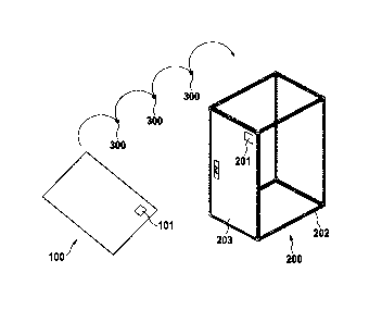
Figures 1 to 3 show an exemplary embodiment of a method according to the
invention
for the machining of at least one switchgear cabinet 200. Figure 1 shows the
manufacture of the switchgear cabinet by the switchgear cabinet builder. This
includes
the raw production of a flat panel 100, for example a switch cabinet side
wall, a switch
cabinet door, or a mounting plate. The flat panel 100 has a component
identification
101, by which the flat panel 100 can be clearly identified.
It is possible that the component identification 101 is arranged on the flat
panel 100 as
early as possible and thus already during the unfinished production of the
flat panel 100
gives the switch cabinet manufacturer the possibility to store the
manufacturing
information individually concerning the flat panel via a data set linked to
the component
identification '101. Thus, for example, it is possible that a data set is
uniquely assigned
via the component identification 101, which contains processing information
during the
manufacturing process of the flat panel 100, for example a mounting plate.
This can
include, for example, the insertion of cut-outs in the mounting plate already
during the
raw production of the mounting plate. If the flat panel 100 is to become a
side panel for
a switch cabinet housing 200, it is possible that already after the production
of the bent
sheet metal blank the component identification 101 is applied to the bent
sheet metal
blank. The data set linked via the component identification 101 can contain
information
regarding the further finishing of the sheet metal blank. This may include,
for example,
Date Recue/Date Received 2020-09-24
CA 03095110 2020-09-24
17
the application of a paint finish, a foamed gasket, or the insertion of fixing
holes for
mounting the flat panel on the switch cabinet. These machining steps are
marked in
Figure 1 with the reference numeral 300 and are generally not limited to any
specific
machining steps.
Depending on the nature of the scope of the machining steps 300 with which the
flat
panel blank 100 is to be finished, it is necessary to design the component
identification
101 in a suitable manner. If, for example, the component identification 101 is
to be
applied before dip coating of the flat panel 100, it is necessary that the
component
identification 101 can be recoated or can still be read in a recoated state.
In the case of
an embodiment of the invention, however, it may be provided that the component
identification 101 is provided in the form of a printed QR code which can only
be applied
after dip coating of the flat panel 100. In this form of the invention, the
painting is not
one of the machining steps which can be carried out after the application of
the
component identification 101 and is therefore not a machining step 300 which
is stored
in the data set associated with the component identification 101.
With reference to Figures 4 and 5, a component identification is presented
which can be
applied before the flat panel is coated and is therefore still fully
functional even when
overcoated.
After the flat panel 100 with the part identification 101 has passed through
the
machining steps 300, it can be assigned to a specific control cabinet 200 via
a control
cabinet identification 201 on the control cabinet 200. If the part 100 is a
standard series
part, the assignment can be done after the flat panel 100 has been completed,
i.e., after
the flat panel 100 has passed all machining steps 300. If the part 100 is a
part that has
undergone individual machining, it may be useful to assign the part 100 to a
specific
control cabinet 200 or a specific control cabinet identification 201 via its
part
identification 101 already during its creation, especially before its
individualization, so
that a clear assignment between the flat panel 100 and the later control
cabinet 200 is
already established when the flat panel 100 is created.
It is thus possible, for example, to assign a data set to the control cabinet
label 201,
which contains project data of the finished control cabinet with the
switchgear
incorporated therein, for example MCAD data, which, among other things, relate
to the
Date Recue/Date Received 2020-09-24
CA 03095110 2020-09-24
18
post-processing of at least one detachably mounted component 100. In this
case, it is
useful to link the MCAD data concerning the component 100 to a specific
component
100 via the component identification 101 already during the manufacturing
process of
the component 100,
The MCAD part number 201 itself can be located on a detachably mounted part of
the
cabinet 200, e.g., on a door 203, where the corresponding part 203, in this
case a door,
can still have a part number 201 as well as the MCAD part number 201.
The component 201 turns the component, in this case the door 203, which has
the
switch cabinet identification 201, into a master component, to which at least
all
removable components of the switch cabinet 200 with a component identification
101
are assigned by assigning the switch cabinet identification 201 to at least
one
component identification 101 of a component 100. All detachably mounted
components,
in particular all flat panels, can have a component identification 101,
regardless of
whether the respective detachably mounted component 100 undergoes individual
post-
processing or whether it is still a standard series product after completion
of the switch
cabinet with the switchgear mounted.
The frame 202 of the switchgear cabinet 200 is usually not subjected to any
reworking
and is a standardized component at least with regard to its geometry, subject
to the fact
that switchgear cabinets with different external dimensions and
correspondingly with
switchgear cabinet frames of different sizes exist.
In principle, the frame 202 can also have a component identification 101,
which is
assigned to the switch cabinet identification 201, which may be desired, for
example, for
order picking work, in order to enable a clear traceability of the frame 202
as well. It is
also conceivable, for example, that the control cabinet identification 201 is
formed on
frame 202. After completion of the control cabinet 200, a data set can be
stored via the
control cabinet label 201, which reflects the product specification of the
finished control
cabinet 200, including, if necessary, individual machining of the cabinet by
the
manufacturer.
Figure 2 illustrates the situation for the panel builder who receives from the
panel builder
the control cabinet 200 described with reference to Figure 1. As has already
been
Date Regue/Date Received 2020-09-24
CA 03095110 2020-09-24
19
described with reference to Figure 1, the enclosure supplied to the panel
builder by the
panel builder can be a series product, or a 200 panel enclosure which,
according to
project data supplied to the panel builder by the panel builder, already has a
certain
degree of individualization, e.g. cut-outs in side panels for the installation
of an air
conditioning unit or the like.
The panel builder will therefore remove at least the mounting plate 100 from
the switch
cabinet housing 1 to form the switch cabinet 104. Accordingly, in Figure 2,
the
detachably mounted component 100 with component identification 101 represents
a
mounting plate. A machining step of the mounting plate 100, after it has been
disassembled and removed from the switchgear housing 200 by the panel builder,
is to
form openings 103 in the mounting plate 100 which are necessary for the
formation of
the switchgear on the mounting plate 100, e.g. for the cable routing or for
the air routing
of cooling air. However, as already described with reference to Figure 1, the
openings
103 can in principle also be formed at the switchgear cabinet manufacturer's
premises,
which is achieved precisely by the data continuity between trades, which is
made
possible precisely by the unambiguous component and switchgear cabinet
identification
of the type specified in the invention.
A further processing step 302 comprises the equipping of the mounting plate
100 with
electrical and/or electronic components 105 and the wiring of the components
to each
other. Corresponding parts lists, a circuit diagram, a wiring diagram and
further auxiliary
assembly information can in turn be assigned via the component identification
101. For
example, the panel builder can be supported in the assembly of the mounting
plate and
the wiring of the components by reading in the identification 101 and
retrieving a data
set linked to the component identification 101, for example with the aid of
"Augmented
Reality". For improved machine recognition of components 105 on the mounting
plate
100, components 105 can have a machine-readable component identification 106.
For
example, by reading in the component identification 101, a data set can be
transferred
to a human-machine interface which displays a circuit diagram linked to the
component
identification 101. Reading in the component identification 106 serves to
illustrate to a
fitter the correct arrangement and wiring of the respective component 106 on
the
mounting plate.
Date Recue/Date Received 2020-09-24
CA 03095110 2020-09-24
Figure 3 illustrates the situation for the end user of the electrical
switchgear. There, the
switchgear cabinet 200 containing the switchgear 104 may be lined up in a row
of
several switchgear cabinets 200. The switchgear 104 on the mounting plate 100
at the
switchgear manufacturer's site as shown in Figure 2 is located in the middle
switchgear
cabinet 200 in the illustration in Figure 3. The end user of the electrical
switchgear 104
is particularly interested in ensuring the operation of the switchgear and the
maintenance of the switchgear by the simplest possible technical means. Here,
too, the
component identification in accordance with the invention can be of
assistance.
For example, the end user of the electrical switchgear can read in the
component
identification 101 during operation of the electrical switchgear. The
operating
parameters of the electrical switchgear 104 are stored in a data set assigned
to the
component identification 101. This can include, for example, the retrieval of
fault
messages or the monitoring of the switchgear operation, for example the output
of at
least one energy consumption value.
If the electrical switchgear 104 has a monitoring unit which monitors the
operation of the
electrical switchgear 104 and corresponding operating parameters are stored in
the data
set which can be retrieved via the component identification 101, the user of
the electrical
switchgear can retrieve the operating parameters recorded by the monitoring
unit via a
man-machine interface 400 by reading the identification 101, for example with
the aid of
an optical camera module of the man-machine interface 400. The corresponding
data
set can be stored in a cloud, which the human-machine interface accesses. In
the
representation shown in Figure 3, a circuit diagram 402 of the electrical
switchgear 104
is shown on a display 401 of the man-machine interface 400. The data set of
the
switchgear monitoring device can be superimposed on the circuit diagram, so
that, for
example, operationally relevant parameters of the individual components of the
electrical switchgear 104 can be displayed in the circuit diagram 402 on the
display 401
assigned to corresponding component symbols, which considerably facilitates
the
maintenance of the electrical switchgear 104.
On the inside of the switchgear cabinet door 109 a circuit diagram pocket 108
with a
further identification 107 can be arranged. Via the identification 107 a data
set can be
deposited analogous to the component identification 101, which shows essential
operating parameters of the electrical switchgear 104. Furthermore, the data
set can
Date Recue/Date Received 2020-09-24
CA 03095110 2020-09-24
21
contain a circuit diagram, a component parts list, physical operating
parameters of the
individual components, a maintenance history of the electrical switchgear and
further
information, which is usually kept in a classical paper circuit diagram
folder, as well as
additional information, such as commissioning information of the electrical
switchgear.
Figure 4 shows an exemplary embodiment of a repaintable component
identification,
which is designed as an electrical contact. It features a weld-on stud 1 with
an external
thread 8 and a socket 10. Via the socket 10, weld-on stud 1 can be welded to a
flat
panel 100 as shown in Figure 1 and thus also electrically connected. Welding
can be
carried out before painting the switch cabinet housing or the flat panel. The
base 10 has
an undercut contour 11 on its outer circumference which can be used to form a
joining
connection between the weld-on stud 1 and the protective cover 2 also shown.
The protective cover 2 can be designed in the form of a plastic cap, for
example. In
deviation from the paint protection caps known from the state of the art, the
protective
cover 2 shown has a part 4 at the bottom edge of the protective cover 2 which
can be
firmly connected to the electrical contact 1 and a part 5 which can be
detached from the
electrical contact 1. The paint protection caps known from the state of the
art are one-
piece. Part 5, which can be detached from electrical contact 1, can, for
example, have
an internal thread corresponding to the external thread 8, via which part 5
can be
screwed onto contact 1. However, part 5, which can be detached from electrical
contact
1, can also be designed in the manner of a cap without internal thread, which
is held on
the weld-on stud 1 only via its predetermined breaking point and the firmly
connected
part 4. Part 4, which is firmly connected to the weld-on stud 1, may, for
example, be
joined to contact 1 via the undercut 11 at the base of contact 1.
The firmly connected part 4 has the non-volatile memory 3 for storing a
component
identification. Part 4, which is firmly connected to weld-on stud 1, is
connected to part 5,
which can be detached from weld-on stud 1, via a predetermined breaking point
6. The
non-volatile memory 3 is a wireless readable memory 3, for example an RFID
transponder. An antenna 7 of the wirelessly readable memory 3 is located along
the
outer circumference of the electrical contact 1 when the protective cover 2 is
placed on
the contact, for example by joining the fixed part 4 to the socket 10. As the
antenna 7
extends along the outer circumference of the socket 10, it is not
electromagnetically
shielded by the weld-on stud 1, which is a metal part. The antenna 7 can be
embedded
Date Recue/Date Received 2020-09-24
CA 03095110 2020-09-24
22
in the firmly connected part 4. Accordingly, the material of the firmly
connected part 4
does not have a significant electromagnetic shielding effect and is, for
example, a
plastic material.
The protective cover 2 has a cover part 12 which is connected at its free edge
9 via a
predetermined breaking point 6 to the part 4 of the protective cover which can
be firmly
connected to the base 10 of the grounding bolt.
Since the non-volatile storage tank 3 with at least one data set, e.g. a
component
identification, is located in the part 4 of the protective cover 2 that can be
firmly
connected to the electrical contact, the storage tank 3 remains on the switch
cabinet
housing when the cover part 12 is detached from the fixed part 4 via the
predetermined
breaking point 6 and the cover part 12 is removed. This means that the
information
stored in memory 3 is retained even if, for example, the cover part 12 of the
protective
cover 2 is unscrewed or released from the thread 8 of the electrical contact
and
removed from the switch cabinet housing to establish an earth contact for
equipotential
bonding.
Figure 5 illustrates an exemplary manufacturing and application process of
weld-on stud
1. In a first step, weld-on stud 1 can be manufactured by connecting it to
protective
cover 2 consisting of the permanently connectable part 4 and the detachable
part 5 in
one joining step with weld-on stud 1.
Subsequently, the weld-on stud 1 provided with the protective cover 2 can be
connected
to a flat panel 22 of a switch cabinet housing via a welding process. If the
protective
cover 2 is then removed from the electrical contact, whereby the weld-on stud
1 is at
least partially exposed and the non-volatile accumulator 3 remains at the
electrical
contact 1, an electrical connection to the switch cabinet housing or the flat
panel 22 can
be established by contacting the electrical contact 1 with a protective
conductor 23. The
protective conductor 23 may have a wire eyelet which is placed on the threaded
section
8 of the weld-on stud 1 and locked with a nut 24. For improved illustration,
Figure 5
shows the farthest right partial representation without the outer casing of
the fixed part
4, so that the non-volatile storage device 3 still remaining at the electrical
contact 1 after
removal of the detachable part 5 is visible in the fixed part 4, even if in
the concrete
Date Recue/Date Received 2020-09-24
CA 03095110 2020-09-24
23
application it is protectively accommodated within a plastic casing of the
fixed part 4, as
shown from the right in the second illustration.
The features of the invention disclosed in the above description, in the
drawings as well
as in the claims may be essential for the realization of the invention either
individually or
in any combination.
Date Recue/Date Received 2020-09-24
. _
CA 03095110 2020-09-24
24
List of reference numerals
1 weld-on stud
2 protective cover
3 non-volatile memory
4 firmly connected part
detachable part
6 predetermined breaking point
7 antenna
8 external thread
9 edge
base
11 undercut contour
12 cover part
switch cabinet housing
21 frame
22 flat panel
23 protective conductor
24 nut
100 detachably mounted component
101 component identification
103 breakthrough
104 switchgear
105 electrical and/or electronic components
106 component identification
107 circuit diagram drawing
108 circuit diagram holder
109 control cabinet door
Date Recue/Date Received 2020-09-24
_
CA 03095110 2020-09-24
200 switch cabinet
201 control cabinet labeling
202 frame
203 control cabinet door
300 machining step
301 insertion of apertures
302 construction of the electrical switchgear
400 human-machine interface
401 display
402 digital circuit diagram
Date Recue/Date Received 2020-09-24
_ _