Note: Descriptions are shown in the official language in which they were submitted.
CA 03095181 2020-09-24
WO 2019/199567
PCT/US2019/025775
- 1 -
PERFORATING SYSTEMS AND
FLOW CONTROL FOR USE WITH WELL COMPLETIONS
TECHNICAL FIELD
This disclosure relates generally to equipment and techniques used in
conjunction with a subterranean well and, in an example described below, more
particularly provides perforating systems and flow control for use with well
completions.
BACKGROUND
Perforating systems are designed to form perforations through a well
casing or other wellbore lining. The perforations permit fluid communication
.. between an earth formation penetrated by the wellbore and an interior of
the
casing. In this manner, fluids can be produced from the formation into the
casing
and then to surface. In other examples, fluids can be injected from the
interior of
the casing into the formation via the perforations.
It will, therefore, be readily appreciated that improvements are continually
needed in the arts of constructing and operating perforating systems, and
controlling flow through perforations. Such improvements can be useful in a
wide
variety of different types of well completions.
CA 03095181 2020-09-24
WO 2019/199567
PCMJS2019/025775
- 2 -
BRIEF DESCRIPTION OF THE DRAWINGS
FIGS. 1A-D are representative partially cross-sectional views of
successive steps in an example of a well completion system and associated
method which can embody principles of this disclosure.
FIG. 2 is a representative partially cross-sectional view of an example of a
perforating assembly that may be used in the FIGS. 1A-D system and method,
and which can embody the principles of this disclosure.
FIGS. 3A & B are representative partially cross-sectional views of
successive steps in another example of the well completion system and
associated method.
FIG. 4 is a representative partially cross-sectional view of another example
of the well completion system and associated method.
FIG. 5 is a representative partially cross-sectional view of another example
of the well completion system and associated method.
FIGS. 6A & B are representative partially cross-sectional views of
successive steps in another example of the well completion system and
associated method.
FIGS. 7A & B are representative partially cross-sectional views of
successive steps in another example of the well completion system and
associated method.
FIGS. 8-13 are representative partially cross-sectional views of additional
examples of the perforating assembly.
FIG. 14 is a representative partially cross-sectional view of another
example of the well completion system and associated method.
FIG. 15 is a representative partially cross-sectional view of another
example of the well completion system and associated method.
- 2a -
SUMMARY
Accordingly, there is described a well completion system, comprising: fluid
flow through a flow passage of a casing having first perforations formed
therein; and
one or more first diverters deployed into the flow passage downhole of a
perforating
assembly, in which the one or more first diverters are deployed separately
from the
perforating assembly, and in which the one or more first diverters and the
perforating
assembly are concurrently displaced through the flow passage by the fluid
flow.
There is also described a well completion method, comprising: flowing fluid
through a flow passage of a casing lining a wellbore; deploying one or more
diverters
and a perforating assembly into the flow passage, in which the perforating
assembly
includes at least one sensor; displacing the diverters and the perforating
assembly
together through the flow passage by the fluid flow; the at least one sensor
detecting
the fluid flow out of existing perforations at a location longitudinally
spaced apart
along the flow passage from the perforator; and ceasing the fluid flow,
thereby
placing a perforator of the perforating assembly at a desired location for
forming new
perforations through the casing.
Date Recue/Date Received 2021-08-11
CA 03095181 2020-09-24
WO 2019/199567
PCT/US2019/025775
- 3 -
DETAILED DESCRIPTION
Representatively illustrated in FIG. 1 is a well completion system 10 and
associated method for use with a subterranean well, which system and method
can embody principles of this disclosure. However, it should be clearly
understood that the system 10 and method are merely one example of an
application of the principles of this disclosure in practice, and a wide
variety of
other examples are possible. Therefore, the scope of this disclosure is not
limited
at all to the details of the system 10 and method described herein and/or
depicted in the drawings.
Using the system 10, multiple zones 12a-c of an earth formation 12
penetrated by a wellbore 14 are to be individually perforated and fractured.
Although three zones 12a-c are depicted in the drawings and described herein,
any number of zones may be completed using the system 10 and method. In
addition, although the zones 12a-c in the FIG. 1 system 10 and method are
completed individually, in other examples multiple zones could be
simultaneously
completed.
In the FIG. 1 example, the wellbore 14 is lined with casing 16 and cement
18. The casing 16 could be any type of segmented, continuous or formed in situ
tubular or wellbore liner, including (but not limited to) the types known to
those
skilled in the art as casing, liner, tubing, pipe, etc. The scope of this
disclosure is
not limited to use of any particular type of casing, or to use of any casing
in the
formation 12.
The cement 18 could be a Portland cement composition or any other type
of seal or sealant for isolating the zones 12a-c from each other in an annulus
20
formed between the wellbore 14 and the casing 16. In other examples, external
casing packers, swellable seals or other sealing devices could be used in
place
of the cement 18. The scope of this disclosure is not limited to use of any
particular type of cement, or to use of any cement in the formation 12.
CA 03095181 2020-09-24
WO 2019/199567
PCT/US2019/025775
- 4 -
The wellbore 14 is illustrated in the figures as being generally horizontal or
highly deviated from vertical. Although the system 10 and method provide
certain
advantages in situations where a well completion is to be performed in a
horizontal or highly deviated wellbore, the wellbore 14 could be generally
vertical
or otherwise deviated in keeping with the scope of this disclosure.
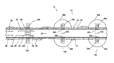
As depicted in FIG. 1A, a perforating assembly 22a is displaced to a
location in the wellbore 14 at which it is desired to form perforations 24a
through
the casing 16 and cement 18, in order to establish fluid communication between
the zone 12a and an interior flow passage 26 of the casing. Although the
perforating assembly 22a and the perforations 24a are both depicted in FIG.
1A,
in some examples the perforating assembly 22a may break up, disintegrate,
dissolve, disperse, degrade or otherwise cease to exist as a distinct
structural
entity as/once the perforations 24a are/have been formed.
For example, the perforating assembly 22a could be made up of materials
that are friable, frangible, dissolvable, subject to galvanic corrosion, or
otherwise
dispersible or degradable in a well environment. The disintegration,
dispersal,
degrading, dissolution, etc., of the perforating assembly 22a may begin at any
point in the method, such as, at introduction of the perforating assembly into
the
well, in response to contact with a particular activating fluid (for example,
a fluid
having a particular pH level or chemical composition) already present or later
introduced into the well or released from a container, in response to shock
produced when a perforator 28 of the perforating assembly is fired to form the
perforations 24a, in response to exposure to an elevated temperature or
pressure, or in response to another event or stimulus. However, note that it
is not
necessary for the perforating assembly 22a to break up, disintegrate,
dissolve,
disperse, degrade or otherwise cease to exist as a distinct structural entity
in
keeping with the scope of this disclosure.
In the FIG. 1A example, the perforating assembly 22a includes the
perforator 28, a firing head 30, a control module 32 and a flow restrictor 34.
In
other examples, the perforating assembly 22a could include other, different,
more
CA 03095181 2020-09-24
WO 2019/199567 PCT/US2019/025775
- 5 -
or less components. The scope of this disclosure is not limited to use of any
particular components or combination of components in a perforating assembly.
The perforator 28 in this example comprises an explosive shaped charge-
type perforator or perforating gun, in which one or more explosive shaped
charges are contained in an outer tubular gun body (see FIG. 2). The shaped
charges are detonated, in order to form the perforations 24a. Other types of
perforators (such as, drills, bullet-type perforating guns, etc.) may be used
in
other examples.
The firing head 30 in this example functions to detonate the shaped
charges in the perforator 28 when desired, for example, by initiating
detonation of
a detonating cord extending to each of the shaped charges. The firing head 30
may initiate the detonation mechanically, electrically, chemically or in any
other
manner, or in response to any event, stimulus or condition. The scope of this
disclosure is not limited to use of any particular type of firing head.
The control module 32 in this example is used to control when or if the
perforator 28 is fired, such as, by controlling when or if the firing head 30
detonates the shaped charges. The control module 32 may cause the firing head
30 to fire the perforator 28 in response to any predetermined number or
combination of events, stimuli or conditions, such as, elapse of time,
pressure or
pattern of pressure variations, flow or pattern of flow variations,
temperature,
vibration or pattern of vibration changes, acceleration or pattern of
acceleration
variations, etc. The scope of this disclosure is not limited to any particular
number
or combination of events, stimuli or conditions that will cause the control
module
to activate the firing head 30.
The flow restrictor 34 in this example is used to restrict flow through an
annulus 36 formed radially between the perforating assembly 22a and the casing
16. As depicted in FIG. 1A, the flow restrictor 34 comprises multiple swab
cups or
cup-type packers that do not necessarily fully seal against the casing 16, but
that
do at least substantially restrict flow through the annulus 36 past the
perforating
assembly 22a (although the flow restrictor could seal against the casing, if
desired).
CA 03095181 2020-09-24
WO 2019/199567 PCT/US2019/025775
- 6 -
In other examples, the flow restrictor 34 could be in the form of a tortuous
path, outwardly extending stiff fibers or bristles, or a gauge ring or other
enlarged
diameter on the perforating assembly 22a. In further examples, the perforating
assembly 22a could be dimensioned so that flow through the annulus 36 is
significantly restricted, without use of a separate flow restrictor. Thus, the
scope
of this disclosure is not limited to use of any particular type of flow
restrictor, or to
use of a flow restrictor at all in the perforating assembly 22a.
Although the perforator 28, firing head 30, control module 32 and flow
restrictor 34 are depicted in the drawings as being separate connected-
together
components of the perforating assembly 22a, in other examples any or all of
the
perforating assembly components could be integral or combined. For example,
the firing head 30 and control module 32 could be a single integrated
component,
the perforator 28, firing head, control module and flow restrictor 34 could be
combined in a single outer housing, etc. Thus, the scope of this disclosure is
not
limited to any particular structural form of the perforating assembly 22a.
In the FIG. 1A example, the perforating assembly 22a is displaced,
transported or conveyed to the desired location for forming the perforations
24a
by a flow of fluid 38 in the flow passage 26. The fluid 38 may be pumped
through
the flow passage 26 by use of one or more pumps at surface (see FIG. 14).
However, the scope of this disclosure is not limited to use of fluid flow to
convey
the perforating assembly 22a, to use of pumps to cause the fluid flow, or to
use of
pumps at any particular location.
The perforating assembly 22a may be conveyed to a desired location by
flowing a corresponding volume of the fluid 38 through the flow passage 26. In
a
simplified example, the volume of fluid required to displace the perforating
assembly 28 a certain distance is given by the formula: V = A x D, in which V
is
the required volume, A is the cross-sectional area of the flow passage 26, and
D
is the distance to the desired location.
As those skilled in the art will appreciate, this simplified example does not
account for variations in the flow passage 26 cross-sectional area, leakage of
the
fluid 38 past the flow restrictor 34, etc. Described more fully below is a
CA 03095181 2020-09-24
WO 2019/199567
PCT/US2019/025775
- 7 -
"calibration" method whereby the volume required to displace the perforating
assembly 22a to a desired location along the wellbore 14 can be determined
(see
FIG. 15).
Once it is known what volume of the fluid 38 is required to be flowed
through the flow passage 26 to displace the perforating assembly 22a to the
desired location, this volume may be measured by use of various techniques or
equipment, such as, by counting pump strokes, by use of a flow meter, etc. The
scope of this disclosure is not limited to use of any particular technique or
equipment for measuring the volume of the fluid 38.
Once the perforating assembly 22a is at the desired location for forming
the perforations 24a, the perforator 28 is fired to thereby form the
perforations. In
one example, the control module 32 may be configured to require the
perforating
assembly 22a to remain motionless for a predetermined period of time, prior to
the perforator 28 being fired. In other examples, the control module 32 could
cause the firing head 30 to fire the perforator 28 immediately upon detecting
that
the perforating assembly 22a is positioned at the desired location, whether or
not
the perforating assembly is motionless. The scope of this disclosure is not
limited
to any particular combination or sequence of events, stimuli or conditions
that will
cause the perforator 28 to be fired at the desired location.
Referring additionally now to FIG. 1B, the zone 12a is fractured after the
perforations 24a are formed. To fracture the zone 12a, a fracturing fluid is
pumped under elevated pressure from the flow passage 26, through the
perforations 24a and into the zone 12a, until the earth fractures (see
fractures
40a depicted in FIG. 1B).
The fracturing fluid may be the same as, or may be pumped concurrently
with, the fluid 38 used to displace the perforating assembly 22a through the
flow
passage 26. Thus, the zone 12a can be fractured immediately after the
perforations 24a are formed. In other examples, the fracturing fluid could be
different from the fluid 38, or the fractures 40a may not be formed
immediately
after the perforations 24a are formed (for example, a period of time may
elapse
after the perforations are formed, e.g., to allow sufficient time for the
perforating
CA 03095181 2020-09-24
WO 2019/199567 PCT/US2019/025775
- 8 -
assembly 22a to dissolve, degrade, be dispersed, etc., prior to the fracturing
operation). The scope of this disclosure is not limited to any particular
timing,
combination or sequence of events associated with forming the perforations 24a
and the fractures 40a.
In addition to the actual fracturing of the zone 12a, the fracturing operation
may include a variety of different techniques or procedures of the type well
known
to those skilled in the art. For example, various stages may be pumped as part
of
the fracturing operation, such as, including pads, gels, breakers, proppant,
stimulation fluids, conformance agents, permeability enhancers, etc. The scope
of this disclosure is not limited to use of any particular number or
combination of
fluids, substances or other agents in procedures associated with the
fracturing
operation.
After or during the fracturing operation (including any associated propping,
breaking, stimulating, conformance or other procedures), one or more plugs or
diverters 42a is/are used to isolate the zone 12a from pressure in the flow
passage 26, so that further fracturing of the zone is prevented. The
diverter(s)
42a may plug the perforations 24a during the fracturing operation (e.g., so
that
flow is diverted from perforations taking more flow to perforations taking
less
flow), or the diverter(s) may plug the perforations at the conclusion of the
fracturing operation. The scope of this disclosure is not limited to any
particular
timing of the diverter(s) 42a preventing outward flow through any or all of
the
perforations 24a.
The diverter(s) 42a may be any type of plugging device or substance
capable of entirely preventing or substantially restricting flow outward into
the
zone 12a via the perforations 24a. The diverter(s) 42a could in some examples
be discrete plugging devices, such as, frac balls or those plugging devices
described more fully in US patent nos. 9523267, 9567824, 9567825, 9567826,
9708883, 9816341, or in US application nos. 15/567779, 15/138685, 15/138968,
15/615136 or 15/609671. The discrete plugging devices may be dispensed into
the flow passage 26 using any of the techniques described more fully in the
above-mentioned US patents and applications, or in US application nos.
- 9 -
15/745608, 15/162334, 15/837502, 62/588150 or 62/638059. However, it should be
clearly understood that discrete plugging devices and dispensing techniques
other
than those described in the above-listed patents and application may be used,
in
keeping with the scope of this disclosure.
The diverter(s) 42a could in some examples be in particulate, gel or other non-
discrete form. For example, substances such as sand, calcium carbonate, poly-
lactic
acid (PLA), ploy-glycolic acid (PGA), polyvinyl alcohol (PVA), anhydrous boron
compounds, particulate nylon, etc., may be used. Many such plugging substances
are described in the US patents and applications listed above, although other
substances may be used in other examples.
The diverter(s) 42a may be dissolvable, dispersible, melt-able, corrodible, or
otherwise degradable in the well. The diverter(s) 42a may self-degrade, or a
particular activating fluid or other condition or stimulus may be required to
cause the
diverter(s) to degrade. In some examples, the diverter(s) 42a may comprise a
mixture
or combination of degradable and non-degradable materials. In other examples,
the
diverter(s) 42a may not be degradable in the well at all. The scope of this
disclosure
is not limited to any particular form, composition or degradability of the
diverter(s)
42a.
The diverter(s) 42a may enter the perforations 24a and seal against a surface
or face of the zone 12a or the fractures 40a. In other examples, the
diverter(s) 42a
may seal off the perforations 24a at an interior of the casing 16, as depicted
in FIG.
1B. The scope of this disclosure is not limited to any particular location at
which the
diverter(s) 42a prevent flow into the zone 12a.
As depicted in FIG. 1B, another perforating assembly 22b has been conveyed
.. or displaced to a desired location for forming perforations 24b into the
zone 12b. The
perforating assembly 22b may be the same as, or different in some respects
from,
the perforating assembly 22a.
Date Recue/Date Received 2021-04-20
CA 03095181 2020-09-24
WO 2019/199567 PCT/US2019/025775
- 10 -
The perforating assembly 22b may be conveyed or displaced to the
desired location in the same manner as described above for the perforating
assembly 22a (such as, by flowing a particular volume of the fluid 38 through
the
flow passage 26), or the perforating assembly 22b could be conveyed or
displaced using another technique (such as, using wireline, slickline, coiled
tubing, jointed tubing, a downhole tractor, etc.).
The perforating assembly 22b may be conveyed or displaced to the
location for forming the perforations 24b after or while the fractures 40a are
being
formed, or after or while the diverter(s) 42a are being used to prevent flow
into
the zone 12a. For example, the perforating assembly 22b could be introduced
into the well and displaced through the wellbore 14 by flow of the fluid 38
while
the fluid is also being used to form the fractures 40a or place the
diverter(s) 42a.
Thus, the scope of this disclosure is not limited to any particular relative
timing
between conveyance of the perforating assembly 22b, forming the fractures 40a
and placing the diverter(s) 42a.
The zone 12b is fractured after the perforations 24b are formed. To form
fractures 40b in the zone 12b, a fracturing fluid is pumped under elevated
pressure from the flow passage 26, through the perforations 24b and into the
zone 12b. The fracturing fluid and associated fracturing operation may be the
same as, or different from, that described above for forming the fractures 40a
in
the zone 12a.
After or during the fracturing operation (including any associated propping,
breaking, stimulating, conformance or other procedures), one or more plugs or
diverters 42b (see FIG. 1C) is/are used to isolate the zone 12b from pressure
in
the flow passage 26, so that further fracturing of the zone is prevented. The
diverter(s) 42b may be the same as, or different from, the diverter(s) 42a
described above.
Referring additionally now to FIG. 1C, another perforating assembly 22c
has been conveyed or displaced to a desired location for forming perforations
24c
into the zone 12c. The perforating assembly 22c may be the same as, or
different
in some respects from, the perforating assemblies 22a,b described above.
CA 03095181 2020-09-24
WO 2019/199567
PCT/US2019/025775
- 11 -
The perforating assembly 22c may be conveyed or displaced to the
desired location in the same manner as described above for the perforating
assemblies 22a,b, or the perforating assembly 22c could be conveyed or
displaced using another technique. The perforating assembly 22c may be
.. conveyed or displaced to the location for forming the perforations 24c
after or
while the fractures 40b are being formed, or after or while the diverter(s)
42b are
being used to prevent flow into the zone 12b.
Referring additionally now to FIG. 1D, the zone 12c is fractured after the
perforations 24c are formed. To form fractures 40c in the zone 12c, a
fracturing
fluid is pumped under elevated pressure from the flow passage 26, through the
perforations 24c and into the zone 12c. The fracturing fluid and associated
fracturing operation may be the same as, or different from, that described
above
for forming the fractures 40a,b in the respective zones 12a,b.
The diverter(s) 42a,b may dissolve, melt, corrode, disperse or otherwise
degrade after the zones 12a-c have been fractured. In some examples, the
diverter(s) 42a,b may flow to surface with fluids 44a-c produced from the
respective zones 12a-c. The scope of this disclosure is not limited to any
particular technique or process for permitting flow between the zones 12a-c
and
the flow passage 26 after all of the zones have been fractured. Note that, in
some
.. examples, the well may be an injection well instead of, or in addition to,
a
production well, in which case production of the fluids 44a-c may not be an
ultimate goal of the well completion.
Referring additionally now to FIG. 2, an example of a perforating assembly
22 that may be used for any of the perforating assemblies 22a-c in the system
10
and method described above is representatively illustrated. In this example,
the
perforator 28, firing head 30 and control module 32 are contained in a same
generally tubular outer housing 46, but in other examples separate housings
may
be used. The scope of this disclosure is not limited to any particular details
of the
perforating assembly 22 as described herein or depicted in the drawings.
The perforator 28 in the FIG. 2 example comprises multiple explosive
shaped charges 48, a detonating cord 50 and an electrical detonator 52. When
CA 03095181 2020-09-24
WO 2019/199567 PCT/US2019/025775
- 12 -
an electric current is applied to the detonator 52, the detonator detonates
and
thereby initiates an explosive chain reaction, in which the detonating cord 50
detonates and thereby causes the shaped charges 48 to detonate.
The shaped charges 48, detonating cord 50 and detonator 52 can be
.. conventional components of the type well known to those skilled in the art,
and so
they are not described further herein. However, it should be understood that
other
mechanisms or techniques (such as, bullet-type perforators, percussive
detonators, drills, etc.) may be used to form perforations, without departing
from
the scope of this disclosure.
The firing head 30 in the FIG. 2 example includes electrical switches 54,
56 connected in series between a battery 58 and the detonator 52. The switch
54
is a fail-safe switch for absolutely preventing electrical current from
flowing
through the detonator 52, unless the switch is activated.
A mechanical or other type of safety mechanism 60 may be used to
prevent activation of the switch 54, for example, during transport of the
perforating assembly 22 to a wellsite, or immediately prior to deployment of
the
perforating assembly 22 into a well. In some examples, the fail-safe switch 54
could be a three-way switch that electrically connects electrical leads of the
detonator 52 to each other, to thereby preclude an electrical potential from
being
created across the leads, until the switch is activated by the safety
mechanism
60.
After the fail-safe switch 54 is activated, the switch 56 can be activated by
the control module 32 downhole. In this example, the control module 32
comprises a controller 62, a memory 64, a timer 66, a pressure sensor 68, a
temperature sensor 70 and an accelerometer or other type of motion sensor 72.
An optional collar locator 74 may be included in some examples.
The controller 62 may be a programmable logic controller (PLC), or
another type of controller capable of activating the switch 56 in response to
a pre-
programmed combination of events, stimuli or conditions as sensed, determined
or measured using the timer 66, pressure sensor 68, temperature sensor 70,
CA 03095181 2020-09-24
WO 2019/199567
PCT/US2019/025775
- 13 -
motion sensor 72 and/or collar locator 74. The memory 64 may be used to store
the combination of events, stimuli or conditions.
The memory 64 may in some examples be used to store well parameters,
such as, casing collar locations, expected downhole temperatures, expected
hydrostatic pressures, desired perforating location, etc. In this manner, the
perforating assembly 22 can be programmed so that it fires in response to
events, stimuli or conditions unique to a particular well completion,
including
unique to a particular zone to be perforated.
In one example, the memory 64 may store instructions that cause the
controller 62 to activate the switch 56 only after a certain minimum amount of
time has elapsed since the perforating assembly 22 was deployed into the well
(as measured by the timer 66), only if a certain level of pressure is detected
by
the pressure sensor 68, only if a certain level of temperature is detected by
the
temperature sensor 70, and only if the perforating assembly 22 has remained
motionless for a certain period of time (e.g., as detected using the motion
sensor
72 and the timer 66). If the collar locator 74 is included in the control
module 32,
the controller 62 may in addition only activate the switch 56 if a certain
number of
casing collars have been detected.
In other examples, different numbers and/or combinations of sensors,
memory, controllers, switches, etc., may be used in the control module 32.
Thus,
the scope of this disclosure is not limited to any particular configuration of
the
control module 32.
The flow restrictor 34 in the FIG. 2 example is in the form of a gauge ring
or other enlarged diameter secured on the outer housing 46. In other examples,
the enlarged diameter could be formed as part of the outer housing 46.
Although not depicted in FIG. 2, the perforating assembly 22 could include
a self-destruct capability, so that the perforating assembly disintegrates,
dissolves, breaks apart or otherwise degrades, if it is not properly fired at
the
desired location in the well (such as, if the sensors 66, 68, 70, 72, 74 do
not
detect a pre-programmed set of events, conditions or stimuli). For example,
the
CA 03095181 2020-09-24
WO 2019/199567
PCT/US2019/025775
- 14 -
perforating assembly 22 could include an explosive charge or a container of
activating fluid (such as an acid or corrosive fluid), whereby the explosive
charge
is detonated or the activating fluid is released in the perforating assembly
after a
certain period of time has elapsed (the period of time being greater than that
at
which it was expected that the pre-programmed set of events, conditions or
stimuli would occur).
The self-destruct capability can prevent a "live" perforating assembly from
being left downhole or retrieved to surface in an unknown or unsafe state.
Alternatively, if, for example, the perforating assembly 22 can reliably be
dissolved or otherwise degraded downhole, the self-destruct capability may not
be used.
Referring additionally now to FIGS. 3A & B, another example of the
system 10 and method are representatively illustrated. In this example, the
diverter(s) 42a are conveyed or displaced through the flow passage 26 with the
perforating assembly 22b after or during the forming of the fractures 40a in
the
zone 12a.
Note that the flow restrictor 34 in the FIGS. 3A & B example is spaced
apart from the remainder of the perforating assembly 22b as the perforating
assembly displaces through the flow passage 26. However, the flow restrictor
34
is connected to the perforator 28, firing head 30 and control module 32 by a
tether 76, so that the perforator is positioned a known distance from the flow
restrictor 34.
As depicted in FIG. 3A, a portion of the flow passage 26 is, thus, defined
between the flow restrictor 34 and the remainder of the perforating assembly
22b.
The diverter(s) 42a are positioned in this portion of the flow passage 26 as
the
perforating assembly 22b displaces through the flow passage.
As depicted in FIG. 3B, when the flow restrictor 34 passes the open
perforations 24a, the diverter(s) 42a can then engage the perforations or
enter
the perforations to thereby prevent flow through the perforations into the
zone
12a. At this point (the flow restrictor 34 having passed the open perforations
24a),
CA 03095181 2020-09-24
WO 2019/199567
PCT/US2019/025775
- 15 -
the perforator 28 is appropriately positioned in the desired location for
forming the
perforations 24b. Flow of the fluid 38 can be ceased, so that the perforating
assembly 22b becomes motionless, and the perforator 28 will eventually fire
(e.g., after a certain period of time, and at or above a certain minimum
pressure
level and temperature level, as described above). In some examples, the
perforator 28 may form the perforations 24b as soon as the control module 32
determines that the perforator is at the desired location for forming the
perforations.
A decreased pressure and/or increased flow rate may be detected by an
operator at surface as an indication that the flow restrictor 34 has passed
the
open perforations 24a. Then, the operator may detect an increased pressure
and/or decreased flow rate when the diverter(s) 42a prevent flow into the zone
12a. These or other indications may be used by the operator to confirm the
operation's progress and to determine when flow of the fluid 38 should be
ceased, so that the perforator 28 is positioned at the desired location for
forming
the perforations 24b.
The configuration of the perforating assembly 22b and diverter(s) 42a in
FIGS. 3A & B may be used in any portion of the system 10 and method. For
example, the FIGS. 3A & B configuration could be used for the perforating
assembly 22c and diverter(s) 42b (see FIG. 1C).
Referring additionally now to FIG. 4, another example of the system 10
and method is representatively illustrated. In this example, the diverter(s)
42 are
releasably attached to the tether 76, at least initially when the perforating
assembly 22 is deployed into the well.
For example, the diverter(s) 42 could be adhered, bonded or otherwise
secured to the tether 76 using a dissolvable material (such as PLA, PGA or
PVA)
so that, after deployment into the well, the diverters are released into the
portion
of the flow passage 26 between the flow restrictor 34 and the remainder of the
perforating assembly 22. In another example, the diverters 42 could be
released
from the tether 76 in response to firing of the perforator 28 (e.g., due to a
mechanical or pressure shock wave caused by the firing), in which case the
CA 03095181 2020-09-24
WO 2019/199567
PCT/US2019/025775
- 16 -
diverters can engage or otherwise prevent flow through the perforations 24
after
the perforator has been fired.
Referring additionally now to FIG. 5, another example of the system 10
and method is representatively illustrated. In this example, the diverter(s)
42 are
contained in a container 78, which may be attached or secured to the flow
restrictor 34 and/or the tether 76. The container 78 may be in the form of a
flexible bag or sack, or the container may be made of a rigid material.
The container 78 may be dissolvable, melt-able or otherwise degradable
downhole to thereby release the diverters 42 into the portion of the flow
passage
26 between the flow restrictor 34 and the remainder of the perforating
assembly
22 after deployment into the well. In some examples, the container 78 may be
designed to release the diverters 42 in response to firing of the perforator
28
(e.g., due to a mechanical or pressure shock wave caused by the firing), in
which
case the diverters can engage or otherwise prevent flow through the
perforations
24 after the perforator has been fired.
Referring additionally now to FIGS. 6A & B, another example of the
system 10 and method is representatively illustrated. In this example, the
diverter(s) 42a are deployed into the flow passage 26 before or "ahead of" the
perforating assembly 22. The perforating assembly 22 and the diverter(s) 42a
are
displaced together through the flow passage 26 by the flow of the fluid 38.
Eventually, the diverter(s) 42a engage the perforations 24a or otherwise
prevent flow through the perforations 24a. At or after this point, the flow of
the
fluid 38 is ceased, so that the perforator 28 is positioned at the desired
location
for forming the perforations 24b.
Additional diverter(s) 42b may be deployed into the flow passage 26 for
displacement with the perforating assembly 22 by the flow of the fluid 38. The
diverter(s) 42b can engage the perforations 24b or otherwise prevent flow out
of
the perforations after the perforator 28 has been fired.
Referring additionally now to FIGS. 7A & B, another example of the
system 10 and method is representatively illustrated. In this example, the
CA 03095181 2020-09-24
WO 2019/199567
PCT/US2019/025775
- 17 -
diverter(s) 42 are contained in the container 78, which is part of the
perforating
assembly 22, or which is attached or secured to the perforating assembly.
As depicted in FIG. 7A, the diverter(s) 42 are displaced or conveyed with
the perforating assembly 22 by the flow of the fluid 38 through the flow
passage
26. The container 78 may be dissolvable, melt-able or otherwise degradable
downhole to thereby release the diverters 42 into the flow passage 26 "ahead
of"
the perforating assembly 22 after deployment into the well.
In some examples, the container 78 may be designed to release the
diverters 42 in response to firing of the perforator 28 (e.g., due to a
mechanical or
pressure shock wave caused by the firing), in which case the diverters can
engage or otherwise prevent flow through the perforations 24 after the
perforator
has been fired. As depicted in FIG. 7B, the perforator assembly 22 and the
container 78 have dissolved, disintegrated or otherwise degraded after firing
of
the perforator 28, so that the diverter(s) 42 now prevent flow into the
perforations
24a, and fracturing fluid 38 can flow through the perforations 24b and into
the
zone 12b to form the fractures 40b.
Referring additionally now to FIG. 8, another example of the perforating
assembly 22 is representatively illustrated. In this example, the container
78, with
the diverter(s) 42 therein is secured to the perforating assembly 22 (similar
to the
FIG. 7A example). However, the perforator 28 includes an additional shaped
charge 80 or other explosive device (or a propellant and bullet, etc.) that is
directed toward the container 78.
When the perforator 28 is fired, the shaped charge or other device 80
pierces, opens, breaks, fractures, disperses or otherwise causes the
diverter(s)
42 to be released from the container 78. In this example, the container 78 may
be
made of a friable or frangible material and/or may be configured to
conveniently
break open in response to firing of the device 80.
Referring additionally now to FIG. 9, another example of the perforating
assembly 22 is representatively illustrated. In this example, the container
78, with
CA 03095181 2020-09-24
WO 2019/199567
PCT/US2019/025775
- 18 -
the diverter(s) 42 therein is secured to the perforating assembly 22 via the
tether
76.
When the perforator 28 is fired, the shaped charge or other device 80
pierces, opens, breaks, fractures, disperses or otherwise causes the
diverter(s)
42 to be released from the container 78, which may be made of a friable or
frangible material and/or may be configured to conveniently break open in
response to firing of the device 80. Alternatively, the firing of the device
80 could
release or break the tether 76, thereby allowing the container 78 with the
diverter(s) 42 therein to separate from the remainder of the perforating
assembly
22. The diverter(s) 42 could be released from the container 78 in response to
dissolution, corrosion, dispersal, melting, breaking or other degrading of the
container.
In the FIG. 9 example, the perforating assembly 22 also includes a drag
device 82 connected to the remainder of the perforating assembly by another
tether 76. As depicted in FIG. 9, the drag device 82 includes pads or arms 84
that
extend outward to resiliently engage an interior surface of the casing 16. In
some
examples, the drag device 82 could be similar to drag blocks of the type used
with mechanically-set packers.
Friction between the drag device arms 84 and the interior surface of the
casing 16 imparts a drag force via the tether 76 to the remainder of the
perforating assembly 22, thereby ensuring that the perforator 28 will remain
"behind" the diverter(s) 42 and container 78, as the perforating assembly 22
is
displaced through the flow passage by the flow of the fluid 38. In this
manner, the
diverter(s) 42 will continue downhole to previously formed perforations,
rather
than engage perforations formed by the perforator 28 to which the container 78
is
attached.
Note that the drag device 82 may be used with any of the perforating
assemblies 22 and methods described herein, in which the diverter(s) 42, 42a-c
are conveyed through the flow passage 26 concurrently with a perforating
assembly (for example, see FIG. 5).
CA 03095181 2020-09-24
WO 2019/199567
PCT/US2019/025775
- 19 -
Referring additionally now to FIGS. 10-13, additional examples of the
perforating assembly 22 are representatively illustrated. In these examples,
the
diverter(s) 42 are secured on an exterior of the perforating assembly 22.
The diverter(s) 42 may be released from the exterior of the perforating
assembly 22 examples of FIGS. 10-13 using any suitable technique. For
example, the diverter(s) 42 could be adhered or bonded to the exterior of the
perforating assembly 22 using a substance that dissolves, melts, corrodes or
otherwise degrades in the well environment, so that the diverter(s) are
released
from the perforating assembly downhole after deployment of the perforating
assembly into the well. In other examples, the diverter(s) 42 could be
attached to
the exterior of the perforating assembly 22 using frangible or friable
fasteners,
clamps or other attachment devices that break in response to shock produced
when the perforator 28 is fired. The scope of this disclosure is not limited
to any
particular technique for releasing the diverter(s) 42 from the exterior of the
perforating assembly 22 downhole.
As depicted in FIG. 10, the diverter(s) 42 are attached, fastened, clamped,
adhered, bonded or otherwise secured to an exterior of the outer housing 46.
The
diverter(s) 42 may be released from the perforating assembly 22 after the
perforating assembly is introduced into the well (e.g., due to contact with an
activating fluid or elevated temperature in the well), or in response to
firing of the
perforator 28.
As depicted in FIG. 11, the diverter(s) 42 are attached, fastened, clamped,
adhered, bonded or otherwise secured in a groove, channel or recess 86 on the
perforating assembly 22. In this example, the recess 86 is formed between
rails
88 secured on the outer housing 46, but in other examples the recess (or
multiple
recesses) could be formed directly in the outer housing, or otherwise arranged
on
the perforating assembly 22. The diverter(s) 42 may be released from the
perforating assembly 22 after the perforating assembly is introduced into the
well
(e.g., due to contact with an activating fluid or elevated temperature in the
well),
or in response to firing of the perforator 28.
CA 03095181 2020-09-24
WO 2019/199567 PCT/US2019/025775
- 20 -
As depicted in FIG. 12, the diverter(s) 42 are attached, fastened, clamped,
adhered, bonded or otherwise secured between multiple flow restrictors 34 on
the
perforating assembly 22. The diverter(s) 42 may be released from the
perforating
assembly 22 after the perforating assembly is introduced into the well (e.g.,
due
to contact with an activating fluid or elevated temperature in the well), or
in
response to firing of the perforator 28.
In other examples, the diverter(s) 42 may be contained between the flow
restrictors 34, without being attached, bonded, etc., to the outer housing 46.
For
example, the "lower" (further downhole) flow restrictor 34 could dissolve or
otherwise degrade downhole (for example, in response to contact with an
activating fluid in the well) to release the diverter(s) 42 from the
perforating
assembly 22.
As depicted in FIG. 13, the diverter(s) 42 are retained on the exterior of the
perforating assembly 22 by a degradable sleeve 90. For example, the sleeve 90
could be made of a material that is capable of "shrinking" onto the
perforating
assembly 22, so that the diverter(s) 42 are captured between the sleeve and
the
outer housing 46. The sleeve 90 could dissolve, melt or otherwise degrade
downhole (e.g., in response to contact with an activating fluid or elevated
temperature in the well), or the sleeve could disperse or break in response to
firing of the perforator 28.
Note that a separate flow restrictor 34 is not depicted for the FIG. 13
example. The perforating assembly 22 in this example could be used without a
separate flow restrictor, or the sleeve 90 could serve as the flow restrictor,
at
least until it degrades to release the diverter(s) 42 (at which point the
perforating
assembly may be disposed in a smaller diameter casing, so that the flow
restrictor 34 is not needed).
Referring additionally now to FIG. 14, an example surface installation 92
for practice of the system 10 and method is representatively illustrated. The
surface installation 92 is depicted as being attached to a wellhead 94 from
which
the casing 16 is hung.
CA 03095181 2020-09-24
WO 2019/199567
PCT/US2019/025775
- 21 -
However, as will be appreciated by those skilled in the art, multiple casing
strings are typically hung from a wellhead facility, so it should be
understood that
the single casing 16 is depicted in FIG. 14 merely for clarity of illustration
and
description. In addition, it is not necessary for the casing 16 in which
perforations
24 are formed in the method to be hung from a surface wellhead facility. Thus,
the scope of this disclosure is not limited at all to the details of the
surface
installation 92 as depicted in FIG. 14.
In the FIG. 14 example, a variety of valves 96 are connected between the
wellhead 94 and pumps 100, 102 for pumping fluid 38 into the flow passage 26.
The valves 96, pumps 100, 102 and a flow head 104 may be of the types
typically used in well fracturing operations.
The perforating assembly 22 may be contained in a tubular housing 106
connected above the flow head 104. The housing 106 and associated
connections, valves, etc., may be of the type commonly referred to by those
skilled in the art as a "lubricator," although other types of housings may be
used if
desired.
The perforating assembly 22 may be deployed into the flow passage 26 by
opening the valves 96 between the pump 102 and the wellhead 94, and
operating the pump 102 to flow the fluid 38 into the well. Any of the
perforating
assemblies 22, 22a-c described herein may be deployed using this technique.
If it is desired to deploy diverter(s) 42 with the perforating assembly 22,
the
diverter(s) may also be contained in the housing 106 with the perforating
assembly. Diverter(s) 42 may be positioned above and/or below the perforating
assembly 22 in the housing 106.
Diverter(s) 42 may be separately deployed into the well by use of a
dispenser 108, for example, connected to the flow head 104. The dispenser 108
may comprise a container 110 for containing the diverter(s) 42 and a valve 98
for
selectively permitting the diverter(s) to enter a flow line 112 connected
between
the pump 100 and the flow head 104. Alternatively, any of the dispensers
CA 03095181 2020-09-24
WO 2019/199567 PCT/US2019/025775
- 22 -
described in the US patents and applications listed above may be used for the
dispenser 108.
The diverter(s) 42 may be deployed into the well by opening the valve 98
and the valves 96 between the pump 100 and the flow head 104, and between
the flow head and the wellhead 94, and operating the pump 100 to flow the
fluid
38 into the well. The diverter(s) 42 may be deployed from the dispenser 108
before and/or after a perforating assembly 22 is deployed.
It is contemplated that the perforating assembly 22 and the diverters 42
will not necessarily displace through the flow passage 26 with the fluid 38 at
a
same speed for a given flow rate. This difference in speeds may be used to
achieve a desired spacing between the perforating assembly 22 and the
diverters
42 in the well (for example, so that the diverters 42 engage previously formed
perforations 24 when, or just after, the perforating assembly 22 arrives at a
desired location for forming new perforations).
In a simplified example, the following equation may be used to determine a
spacing between the diverters 42 and the perforating assembly 22: S = (SD ¨
SPA) x T, in which S is the spacing, SD is the speed of the diverters 42 at a
given
fluid 38 flow rate, SPA is the speed of the perforating assembly 22 at the
given
flow rate, and T is the elapsed time. The diverters 42 and perforating
assembly
22 may also, or alternatively, be released into the flow passage 26 at
different
times, in order to achieve a desired spacing between them.
Referring additionally now to FIG. 15, an example of a calibration method
that may be used with the system 10 is representatively illustrated. The FIG.
15
method may be used to determine the volume of fluid 38 that should be flowed
through the flow passage 26, in order to position a perforating assembly 22 at
a
desired location for forming perforations 24 (see, e.g., FIG. 4).
In the FIG. 15 method, a plug or "pig" 114 is introduced into the flow
passage 26, and then the fluid 38 is pumped into the flow passage behind the
pig, in order to displace the pig through the flow passage, similar to the
manner
described above for the perforating assembly 22. The volume of the fluid 38
CA 03095181 2020-09-24
WO 2019/199567 PCT/US2019/025775
- 23 -
flowed into the passage 26 is monitored during this process. Note that the
fluid 38
used in this calibration method is not necessarily the same as the fluid used
to
convey the perforating assembly 22 or diverters 42 through the passage 26, or
the same fluid used to form the fractures 40.
Eventually, the pig 114 will engage a restriction 116 positioned at a known
distance along the flow passage 26. An operator at surface will note a
pressure
increase and/or a flow rate decrease as an indication that the pig 114 has
engaged the restriction 116.
In the FIG. 15 example, the restriction 116 comprises a cementing shoe
connected proximate a distal end of the casing 16. However, other types of
restrictions (such as liner hangers, bridge plugs, etc.) may be used in other
examples.
Since the restriction 116 is at a known distance along the flow passage 26,
and the volume of the fluid 38 required to displace the pig 114 to the
restriction is
measured in the FIG. 15 method, a determination can be conveniently made as
to what volume of fluid is required to displace the perforating assembly 22
through the flow passage to a desired location.
In a simplified example, the following equation may be used: VRA = VpR X
(DpA/DpR), in which VRA is the volume to displace the perforating assembly 22
to
the desired location, VpR is the volume to displace the pig 114 to the
restriction
116, DpA is the distance to the desired location of the perforating assembly,
and
DpR is the distance to the restriction.
The above equation results from assumptions, including that the flow
passage 26 has a consistent cross-sectional area to the restriction 116, and
that
the perforating assembly 22 and the pig 114 displace the same in response to
the flow of the fluid 38. In some circumstances (for example, long horizontal
wellbores with long productive intervals), inaccuracies due to these
assumptions
may be acceptable. To reduce the inaccuracies, differences in the flow passage
26 cross-sectional area can be accounted for, and the pig 114 can be
configured
to displace the same as the perforating assembly 22 in response to the fluid
flow
CA 03095181 2020-09-24
WO 2019/199567
PCT/US2019/025775
- 24 -
(or the differences between the displacements of the pig and the perforating
assembly could be empirically determined and accounted for).
The above disclosure provides to the art a well completion system 10. In
one example, the well completion system 10 may comprise fluid 38 flow through
a flow passage 26 of a casing 16 having first perforations 24a formed therein.
One or more first diverters 42a are deployed into the flow passage 26 downhole
of a perforating assembly 22. The one or more first diverters 42a and the
perforating assembly 22 are concurrently displaced through the flow passage 26
by the fluid 38 flow.
In any of the well completion systems 10 described herein, the perforating
assembly 22 may be free of any umbilical (such as, a coiled tubing, wireline,
slickline, segmented tubing, etc.) as it is displaced through the flow passage
26
by the fluid 38 flow. The perforating assembly 22 in these examples may not be
connected to the surface via any unbilical.
In any of the well completion systems 10 described herein, one or more
second diverters 42b may be deployed into the flow passage 26 uphole of the
perforating assembly 22, so that the second diverters 42b and the perforating
assembly 22 are concurrently displaced by the fluid 38 flow through the flow
passage 26.
In any of the well completion systems 10 described herein, the first
diverters 42a may block the fluid 38 flow through the first perforations 24a.
In any of the well completion systems 10 described herein, the perforating
assembly 22 may be configured to degrade after the perforating assembly 22
forms second perforations 24b through the casing 16. In any of the well
completion systems 10 described herein, one or more second diverters 42b may
be deployed into the flow passage 26 uphole of the perforating assembly 22,
and
the second diverters 42b may block flow through the second perforations 24b.
In any of the well completion systems 10 described herein, fractures 40a
may be formed into an earth formation 12 by the fluid 38 flow through the
first
CA 03095181 2020-09-24
WO 2019/199567 PCT/US2019/025775
- 25 -
perforations 24a concurrently with the perforating assembly 22 and first
diverters
42a being displaced through the flow passage 26 by the fluid 38 flow.
In any of the well completion systems 10 described herein, the perforating
assembly 22 may be displaced by the fluid 38 flow to a desired location along
the
wellbore 14, and a perforator 28 of the perforating assembly 22 may fire only
if
the perforating assembly 22 remains motionless at the desired location for a
predetermined period of time.
In any of the well completion systems 10 described herein, the perforating
assembly 22 may include a collar locator 74, and a perforator 28 of the
perforating assembly 22 may fire only if the collar locator 74 detects a
predetermined number of casing collars.
In any of the well completion systems 10 described herein, the perforating
assembly 22 may include a flow restrictor 34 that restricts flow through an
annulus 36 formed between the perforating assembly 22b and the casing 16. In
any of the well completion systems 10 described herein, the first diverters
42a
may be retained between a flow restrictor 34 and a perforator 28 of the
perforating assembly 22.
In any of the well completion systems 10 described herein, the first
diverters 42a may be contained in a container 78 between the flow restrictor
34
and the perforating assembly 22. In any of the well completion systems 10
described herein, the first diverters 42a may be contained in a container 78
that is
configured to degrade downhole and release the first diverters 42a from the
container 78.
In any of the well completion systems 10 described herein, a flow restrictor
34 may be connected to the perforating assembly 22 by a tether 76. In any of
the
well completion systems 10 described herein, the first diverters 42a may be
releasably attached to the tether 76. In any of the well completion systems 10
described herein, the first diverters 42a may be released from the tether 76
downhole.
CA 03095181 2020-09-24
WO 2019/199567
PCT/US2019/025775
- 26 -
The above disclosure also provides to the art a well completion method. In
one example, the method can comprise: flowing fluid 38 through a flow passage
26 of a casing 16 lining a wellbore 14; deploying one or more diverters 42 and
a
perforating assembly 22 into the flow passage 26; displacing the diverters 42
and
the perforating assembly 22 together through the flow passage 26 by the fluid
38
flow; and ceasing the fluid 38 flow, thereby placing the perforating assembly
22 at
a desired location for forming perforations 24 through the casing 16.
In any of the well completion methods described herein, the deploying step
may comprise deploying the diverters 42 into the flow passage 26 prior to
deploying the perforating assembly 22 into the flow passage 26, so that the
diverters 42 precede the perforating assembly 22 through the flow passage 26.
In
any of the well completion methods described herein, the deploying step may
comprise deploying the diverters 42 into the flow passage 26 after deploying
the
perforating assembly 22 into the flow passage 26, so that the diverters 42
follow
the perforating assembly 22 through the flow passage 26.
In any of the well completion methods described herein, the method can
comprise the diverters 42 blocking the fluid 38 flow through the perforations
24. In
any of the well completion methods described herein, the ceasing may comprise
the diverters 42 blocking the fluid 38 flow through the perforations 24. As
used
herein, the phrase "blocking the fluid 38 flow through the perforations 24"
does
not require that a diverter 42 seals against the perforation itself since, as
described above, a suitable diverter may pass through the perforation and
engage a face of the earth formation 12, instead of or in addition to engaging
the
perforation itself.
In any of the well completion methods described herein, the method can
comprise the perforating assembly 22 degrading downhole after the perforating
assembly 22 forms the perforations 24 through the casing 16.
In any of the well completion methods described herein, the method can
comprise forming fractures 40 into an earth formation 12 by the fluid flow 38
concurrently with the displacing of the perforating assembly 22 and/or the
diverters 42 through the flow passage 26 by the fluid 38 flow.
CA 03095181 2020-09-24
WO 2019/199567
PCT/US2019/025775
- 27 -
In any of the well completion methods described herein, the flowing step
can comprise restricting the fluid 38 flow through an annulus 36 formed
between
the perforating assembly 22 and the casing 16.
In any of the well completion methods described herein, the method can
comprise firing a perforator 28 of the perforating assembly 22 in response to
the
perforating assembly 22 remaining motionless at the desired location for a
predetermined period of time.
In any of the well completion methods described herein, the perforating
assembly 22 may include a collar locator 74, and the method may comprise
firing
a perforator 28 of the perforating assembly 22 in response to the collar
locator 74
detecting a predetermined number of casing collars.
In any of the well completion methods described herein, the method can
comprise retaining the diverters 42 between a flow restrictor 34 and a
perforator
28 of the perforating assembly 22.
In any of the well completion methods described herein, the method may
further comprise containing the diverters 42 in a container 78, and degrading
the
container 78 downhole, thereby releasing the diverters 42 from the container
78.
In any of the well completion methods described herein, the method can
comprise containing the diverters 42 in a container 78 between the flow
restrictor
34 and the perforating assembly 22.
In any of the well completion methods described herein, the method can
comprise connecting a flow restrictor 34 to the perforating assembly 22 by a
tether 76. In any of the well completion methods described herein, the method
can comprise releasably attaching the diverters 42 to the tether 76. In any of
the
well completion methods described herein, the method can comprise releasing
the diverters 42 from the tether 76 down hole.
A perforating assembly 22 for use in a subterranean well is also provided
to the art by the above disclosure. In one example, the perforating assembly
22
can comprise: a perforator 28, and a control module 32 including a memory 64,
a
motion sensor 72, a timer 66, and a controller 62 that causes the perforator
28 to
CA 03095181 2020-09-24
WO 2019/199567
PCT/US2019/025775
- 28 -
fire in response to a lack of motion sensed by the motion sensor 72 for a
predetermined period of time.
In any of the perforating assemblies 22 described herein, the perforating
assembly 22 may comprise a collar locator 74, and the controller 62 may cause
the perforator 28 to fire in response to the lack of motion sensed by the
motion
sensor 72 for the predetermined period of time after detection of a
predetermined
number of casing collars by the collar locator 74.
In any of the perforating assemblies 22 described herein, the perforating
assembly 22 can comprise a collar locator 74, and the perforator 28 of the
perforating assembly 22 may fire only if the collar locator 74 detects a
predetermined number of casing collars.
In any of the perforating assemblies 22 described herein, one or more
diverters 42 may be retained between a flow restrictor 34 and the perforator
28 of
the perforating assembly 22.
In any of the perforating assemblies 22 described herein, the diverters 42
may be contained in a container 78 between the flow restrictor 34 and the
perforating assembly 22. In any of the perforating assemblies 22 described
herein, the container 78 may be configured to degrade downhole and release the
diverters 42 from the container 78.
In any of the perforating assemblies 22 described herein, a flow restrictor
34 may be connected to the perforating assembly 22 by a tether 76. In any of
the
perforating assemblies 22 described herein, one or more diverters 42 may be
releasably attached to the tether 76.
Another perforating assembly 22 example described above can comprise:
a perforator 28, and one or more diverters 42 attached to the perforator 28.
In any of the perforating assemblies 22 described herein, the diverters 42
may be attached exterior to the perforator 28. In any of the perforating
assemblies 22 described herein, the diverters 42 may be secured to an outer
housing 46 of the perforating assembly 22.
CA 03095181 2020-09-24
WO 2019/199567
PCT/US2019/025775
- 29 -
Another well completion method described above can comprise: flowing
fluid 38 through a flow passage 26 of a casing 16 lining a wellbore 14;
deploying
a perforating assembly 22 into the flow passage 26; and displacing the
perforating assembly 22 through the flow passage 26 by the fluid 38 flow at a
predetermined flow rate for a predetermined flow time; and ceasing the fluid
38
flow at an end of the predetermined flow time, thereby placing the perforating
assembly 22 at a desired location for forming perforations 24 through the
casing
16.
In any of the well completion methods described herein, the method may
comprise displacing a plug (such as the pig 114) to a predetermined location
along the flow passage 26, thereby determining a volume of the fluid 38
corresponding to displacement of the perforating assembly 22 to the desired
location along the flow passage 26. In any of the well completion methods
described herein, the predetermined location may comprise a restriction 116 in
the flow passage 26.
In any of the well completion methods described herein, the ceasing step
may comprise one or more diverters 42 blocking the fluid 38 flow through the
perforations 24 in the casing 16. In any of the well completion methods
described
herein, the perforating assembly 22 may be displaced to the desired location,
without use of a collar locator 74.
Although various examples have been described above, with each
example having certain features, it should be understood that it is not
necessary
for a particular feature of one example to be used exclusively with that
example.
Instead, any of the features described above and/or depicted in the drawings
can
be combined with any of the examples, in addition to or in substitution for
any of
the other features of those examples. One example's features are not mutually
exclusive to another example's features. Instead, the scope of this disclosure
encompasses any combination of any of the features.
Although each example described above includes a certain combination of
features, it should be understood that it is not necessary for all features of
an
CA 03095181 2020-09-24
WO 2019/199567
PCT/US2019/025775
- 30 -
example to be used. Instead, any of the features described above can be used,
without any other particular feature or features also being used.
It should be understood that the various embodiments described herein
may be utilized in various orientations, such as inclined, inverted,
horizontal,
vertical, etc., and in various configurations, without departing from the
principles
of this disclosure. The embodiments are described merely as examples of useful
applications of the principles of the disclosure, which is not limited to any
specific
details of these embodiments.
In the above description of the representative examples, directional terms
(such as "above," "below," "upper," "lower," "upward," "downward," etc.) are
used
for convenience in referring to the accompanying drawings. However, it should
be
clearly understood that the scope of this disclosure is not limited to any
particular
directions described herein.
The terms "including," "includes," "comprising," "comprises," and similar
terms are used in a non-limiting sense in this specification. For example, if
a
system, method, apparatus, device, etc., is described as "including" a certain
feature or element, the system, method, apparatus, device, etc., can include
that
feature or element, and can also include other features or elements.
Similarly, the
term "comprises" is considered to mean "comprises, but is not limited to."
Of course, a person skilled in the art would, upon a careful consideration
of the above description of representative embodiments of the disclosure,
readily
appreciate that many modifications, additions, substitutions, deletions, and
other
changes may be made to the specific embodiments, and such changes are
contemplated by the principles of this disclosure. For example, structures
disclosed as being separately formed can, in other examples, be integrally
formed and vice versa. Accordingly, the foregoing detailed description is to
be
clearly understood as being given by way of illustration and example only, the
spirit and scope of the invention being limited solely by the appended claims
and
their equivalents.