Note: Descriptions are shown in the official language in which they were submitted.
CA 03095479 2020-09-28
DESCRIPTION
Invention Title
MEMBRANE APPARATUS HAVING IMPROVED FORWARD OSMOSIS
PERFORMANCE AND METHOD FOR SEPARATING SOLUTION USING SAME
[Technical Field]
The present invention relates to a membrane separation apparatus and a
method of separating a solution.
[Background Art]
Generally, a membrane used to separate chemicals or water, such as
petroleum, refinery, chemistry, fine chemistry, a shale gas process, toxic gas
disposal, wastewater treatment, and desalination of seawater, is a
semipermeable
membrane with functions such as forward osmosis, reverse osmosis, selective
gas
separation, and pervaporation.
The membrane has properties such as hydrophilic, hydrophobic,
organophilic, and organophobic, thereby, being used to selectively separate
each
of the chemicals due to a difference in property, such as intermolecular
diffusivity
due to a difference in concentration, a difference in charge repulsion, and a
difference in molecular size.
A method of separating the chemicals using the membrane is to use a
membrane apparatus with specific functions. For example, if a forward osmosis
membrane is used, a forward osmosis membrane apparatus and a reverse
osmosis membrane apparatus assembled independently can be used to separate
the permeate from the feed solution. If the above¨described independent
membrane apparatuses are used, there is a problem that the apparatus is
expensive and a large space is required.
The forward osmosis membrane apparatus includes a feed section in which
a liquid containing a substance to be separated is supplied, and a draw
solution
1
Date Recue/Date Received 2020-09-28
CA 03095479 2020-09-28
section or a permeate section in which a draw solution is supplied and a
substance
that passes through a forward osmosis membrane is mixed with the draw
solution.
At this circumstance, the chemicals (permeate) selectively passing through the
forward osmosis membrane is slowly diffused by diffusion of molecules in the
osmotic solution, and it affects to the slow chemical diffusion rate from the
forward osmosis membrane in the vicinity of the forward osmosis membrane. As
the result, an osmotic pressure difference between two sides adjacent to the
membrane is reduced, and thereby, a separation performance through the forward
osmosis membrane is reduced.
In order to solve this problem, a diffusion speed can be increased by
enhancing the membrane properties which able to increase the substance
penetration to the draw solution section of the forward osmosis membrane, but
since the diffusion speed is not remarkably increased, there is not enough
effect to
improve the forward osmosis performance. In addition, in order to increase a
diffusion effect of the chemicals, a method of making a draw solution pass
through at a high¨speed circulation can be used such that the draw solution
can
form turbulence in the draw solution portion space. However, there is a
problem
that the draw solution has to be circulated for this purpose, and even if the
draw
solution is made to pass through an apparatus at a high speed, a concentration
of
the draw solution is inevitably decreased by the chemicals while passing
through
the apparatus, and thus, the problem that the forward osmosis performance is
decreased is not solved.
FIG. 17 illustrates a fresh water flux according to NaCI concentration as the
draw solution. NaCI solution is used as the draw solution in a forward osmosis
membrane apparatus to desalinate seawater having the NaCI concentration of 0.6
mol/L. Theoretically, the higher the NaCI concentration of the osmotic liquid,
the
higher the fresh water flux has to be, but in actual operation, water passing
through
2
Date Recue/Date Received 2020-09-28
CA 03095479 2020-09-28
the forward osmosis membrane from the seawater is mixed with the osmotic
solution and is not rapidly diffused in the vicinity of the osmotic membrane,
and
thereby, the fresh water flux is remarkably reduced.
In order to solve this problem, a forward osmosis¨membrane distillation unit
can be configured by integrating a forward osmosis membrane with a membrane
distillation membrane. However, the membrane distillation membrane has pores
and evaporates the osmotic solution to discharge a gas phase material through
the
pores in the membrane distillation membrane, resulting in high energy
consumption. In addition, if the membrane distillation membrane is made to be
in
a wet state due to water blocking the pores, a material that has to be
separated by
being evaporated cannot escape through the pores. Therefore, if it is
mandatory
that a hydrophobic membrane is used to separate the material due to the
hydrophilic property of a separation membrane, there are restrictions on use.
For
this reason, it is difficult to constantly keep a concentration of a forward
osmosis
draw solution diluted by a filtration liquid passed through the forward
osmosis
membrane.
Another solution to the problem is to configure a forward osmosis¨filter unit
by integrating a forward osmosis membrane with a microfilter, a nanofilter or
an
ultrafilter. However, if a substance having small molecules is used as a draw
solution so as to filter water by using a filter, the draw solution passing
through the
filter can be lost, and thereby, there is a restriction that only a polymer
substance
solution has to be used as the draw solution. However, if the polymer
substance
solution is used as the draw solution, an osmotic pressure difference is
reduced,
and thus, there is a problem that the amount of water passing through the
forward
osmosis membrane becomes is reduced.
[Citation List]
3
Date Recue/Date Received 2020-09-28
CA 03095479 2020-09-28
[Patent Document]
(Patent Document 1) Korean Patent Publication No. 10-2017-0047090:
Energy saving Forward Osmosis¨filtration hybrid Water treatment/seawater
desalination system using big size polymer draw solute and method of Water
treatment/seawater desalination using the same
(Patent Document 2) U.S. Patent Publication No. 2010/0224476:
COMBINED MEMBRANE¨DISTILLATION¨FORWARD¨OSMOSIS SYSTEMS AND
METHODS OF USE
[Disclosure]
[Technical Problem]
An object to be solved is to provide a membrane apparatus with improved
forward osmosis performance.
Another object to be solved is to provide a membrane apparatus which has
a small footprint.
Still another object to be solved is to provide a method of separating a
solution in which forward osmosis performance is improved.
However, the objects are not limited to the above disclosure.
[Technical Solution]
In one aspect, there is provided a membrane apparatus including a
housing, a forward osmosis membrane that divides an internal space of the
housing into an inlet region and a mixing region, and a pervaporation membrane
that divides the internal space of the housing into the mixing region and a
discharge region, in which the forward osmosis membrane separates a
preliminary
filtration liquid from an inlet liquid which is provided in the inlet region
and provides
the separated preliminary filtration liquid to the mixing region, in which the
preliminary filtration liquid is mixed with a forward osmosis draw solution in
the
mixing region to make a mixed solution, in which the pervaporation membrane
4
Date Recue/Date Received 2020-09-28
CA 03095479 2020-09-28
separates a final filtration liquid from the mixed solution and provides the
separated final filtration liquid to the discharge region, and in which the
final
filtration liquid is vaporized in the discharge region to make vapor.
The membrane apparatus may further include a control portion that adjusts
at least one of a temperature of the mixed solution and a degree of vacuum of
the
discharge region. The amount of vapor may be adjusted by at least one of the
temperature of the mixed solution and the degree of vacuum of the discharge
region.
The forward osmosis draw solution may include a mineral salt, and the
mineral salt may include a sodium chloride (NaCI) solution.
The degree of vacuum of the discharge region and the temperature of the
mixed solution may be adjusted corresponding to a solute concentration of the
mixed solution.
The membrane apparatus may further include an inlet liquid supply portion
that supplies an inlet liquid to the inlet region, a condenser that condenses
the
vapor to regenerate a final filtration liquid, and a vacuum pump that adjusts
the
degree of vacuum of the discharge region.
The forward osmosis membrane may have a flat plate shape, and the
pervaporation membrane may have a flat plate shape and is arranged in parallel
with the forward osmosis membrane.
The forward osmosis membrane and the pervaporation membrane may
have a tube shape or a hollow fiber shape.
A plurality of the forward osmosis membranes or a plurality of the
pervaporation membranes may be provided.
The membrane chamber may further include a reverse osmosis membrane
that divides the mixing region into a first mixing region and a second mixing
region.
In another aspect, there is provided a method of separating a solution using
Date Recue/Date Received 2020-09-28
CA 03095479 2020-09-28
a membrane apparatus including preparing a membrane chamber including a
housing, a forward osmosis membrane that divides an internal space of the
housing into an inlet region and a mixing region, and a pervaporation membrane
that divides the internal space of the housing into the mixing region and a
discharge region; providing an inlet liquid and a forward osmosis draw
solution to
the inlet region and the mixing region, respectively; mixing the preliminary
filtration
liquid that is separated from the inlet liquid with the forward osmosis draw
solution
to make a mixed solution; and providing a final filtration liquid that is
separated
from the mixed solution to the discharge region to evaporate the final
filtration
liquid in the discharge region.
The method of separating the solution using the membrane apparatus may
further including controlling at least one of a temperature of the mixed
solution and
a degree of vacuum of the discharge region corresponding to the solute
concentration of the mixed solution, and the amount of evaporation of the
final
filtration liquid may be adjusted by at least one of the temperature of the
mixed
solution and the degree of vacuum of the discharge region.
The method of separating a solution using the membrane apparatus may
further including condensing the vapor to regenerate the final filtration
liquid.
The method of separating a solution using the membrane apparatus may be
provided in which an osmotic pressure of the mixed solution is constantly
maintained.
[Advantageous Effects]
A membrane apparatus with improved forward osmosis performance may
be provided.
A small footprint membrane apparatus may be provided.
A method of separating a solution in which forward osmosis performance is
improved may be provided.
6
Date Recue/Date Received 2020-09-28
CA 03095479 2020-09-28
However, the effects are not limited to the above disclosure.
[Description of Drawings]
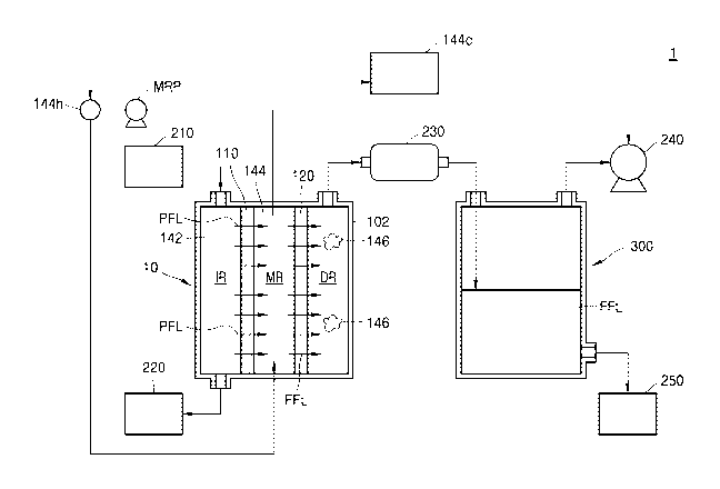
FIG. 1 is a block diagram of a membrane apparatus according to
exemplary embodiments.
FIG. 2 is a flowchart illustrating an operation of the membrane apparatus of
FIG. 1.
FIG. 3 is a block diagram of a membrane apparatus according to the
exemplary embodiments.
FIG. 4 is a sectional diagram of a membrane chamber of FIG. 3.
FIG. 5 is a block diagram of a membrane apparatus according to the
exemplary embodiments.
FIG. 6 is a block diagram of a membrane apparatus according to the
exemplary embodiments.
FIG. 7 is a sectional diagram of a membrane chamber of FIG. 6.
FIG. 8 is a block diagram of a membrane apparatus according to the
exemplary embodiments.
FIG. 9 is a block diagram of a membrane apparatus according to the
exemplary embodiments.
FIG. 10 is a sectional diagram of a membrane chamber of FIG. 9.
FIG. 11 is a block diagram of a membrane apparatus according to the
exemplary embodiments.
FIG. 12 is a block diagram of a membrane apparatus according to the
exemplary embodiments.
FIG. 13 is a sectional diagram of a membrane chamber of FIG. 12.
FIG. 14 is a block diagram of a membrane chamber according to the
exemplary embodiments.
FIG. 15 is a block diagram of a membrane chamber according to the
7
Date Recue/Date Received 2020-09-28
CA 03095479 2020-09-28
exemplary embodiments.
FIG. 16 is a block diagram of a membrane chamber according to the
exemplary embodiments.
FIG. 17 is a graph illustrating a fresh water flux according to NaCI
concentration as the draw solution. NaCI solution is used as the draw solution
in a
forward osmosis membrane apparatus to desalinate seawater having the NaCI
concentration of 0.6 mol/L.
[Best Model
In one aspect, there is provided a membrane apparatus including a
housing, a forward osmosis membrane that divides an internal space of the
housing into an inlet region and a mixing region, and a pervaporation membrane
that divides the internal space of the housing into the mixing region and a
discharge region, in which the forward osmosis membrane separates a
preliminary
filtration liquid from an inlet liquid which is provided in the inlet region
and provides
the separated preliminary filtration liquid to the mixing region, in which the
preliminary filtration liquid is mixed with a forward osmosis draw solution in
the
mixing region to make a mixed solution, in which the pervaporation membrane
separates a final filtration liquid from the mixed solution and provides the
separated final filtration liquid to the discharge region, and in which the
final
filtration liquid is vaporized in the discharge region to make vapor.
In another aspect, there is provided a method of separating a solution using
a membrane apparatus including preparing a membrane chamber including a
housing, a forward osmosis membrane that divides an internal space of the
housing into an inlet region and a mixing region, and a pervaporation membrane
that divides the internal space of the housing into the mixing region and a
discharge region; providing an inlet liquid and a forward osmosis draw
solution to
the inlet region and the mixing region, respectively; mixing the preliminary
filtration
8
Date Recue/Date Received 2020-09-28
CA 03095479 2020-09-28
liquid that is separated from the inlet liquid with the forward osmosis draw
solution
to make a mixed solution; and providing a final filtration liquid that is
separated
from the mixed solution to the discharge region to evaporate the final
filtration
liquid in the discharge region.
[Mode for Invention]
Hereinafter, embodiments of the present invention will be described in detail
with reference to the accompanying drawings. In the following drawings, like
reference numerals or symbols refer to elements, and a size of each element in
the
drawings can be exaggerated for the sake of clear and convenient description.
Meanwhile, the embodiments described below are merely illustrative, and
various
modifications can be made from the embodiments.
Hereinafter, what is referred to as "upper portion" or "upper" can include not
only being directly on in a contacted state, but also being directly on
without contact.
A singular form includes plural expressions unless expressly stated otherwise
in the context. In addition, when it is described that a certain portion
includes a
certain configuration element, it means that the certain portion can further
include
other elements, not excluding other elements unless stated otherwise in
particular.
A term such as "-portion", which is described in the specification, means a
unit for processing at least one function or operation, which can be realized
by
hardware or software or can be realized by a combination of the hardware and
the
software.
FIG. 1 is a block diagram of a membrane apparatus according to exemplary
em bodim ents.
Referring to FIG. 1, a membrane apparatus 1 including a membrane chamber
10, an inlet liquid supply portion 210, a residue processing portion 220, a
condenser
9
Date Recue/Date Received 2020-09-28
CA 03095479 2020-09-28
230, a vacuum pump 240, a filtration liquid storage portion 250, and a liquid
collection chamber 300 can be provided.
The membrane chamber 10 can include a housing 102, an inlet region IR, a
mixing region MR, a discharge region DR, a forward osmosis membrane 110, and a
pervaporation membrane 120. The housing 102 can include a material that
resists
an internal pressure of the housing 102.
The inlet region IR can store an inlet liquid 142. The inlet liquid 142 can be
supplied to the inlet region IR from the inlet liquid supply portion 210. A
valve (not
illustrated) and a pump (not illustrated) can be provided between the inlet
liquid
supply portion 210 and the membrane chamber 10 to control a flow of the inlet
liquid
142. The inlet liquid 142 may be a solution in which a preliminary filtration
liquid
PFL and a residue are mixed. The preliminary filtration liquid PFL can include
a
solvent of the inlet liquid 142. For example, the inlet liquid 142 may be sea
water
or waste water, and the preliminary filtration liquid PFL may be water.
The preliminary filtration liquid PFL and the inlet liquid 142 can be
separated
from each other by a forward osmosis phenomenon which will be described below.
The inlet liquid 142 separated from the preliminary filtration liquid PFL can
be
provided to the residue processing portion 220 from the membrane chamber 10.
The residue processing portion 220 can discard the inlet liquid 142 separated
from
the preliminary filtration liquid PFL.
The mixing region MR can store the mixed solution 144. The mixed solution
144 can include the preliminary filtration liquid PFL and a forward osmosis
draw
solution. The forward osmosis draw solution can contain a substance being in
an
ionic state in an aqueous solution. For example, the forward osmosis draw
solution
can contain mineral salt, such as S02, MgCl2, CaCl2, NaCI, KCI, MgSO4, KNO3,
NH4HCO3, NaHCO3, or aluminum sulfate, polymer chemicals such as aliphatic
alcohol, glucose, fructose, and sucrose, or a combination thereof. A solute
Date Recue/Date Received 2020-09-28
CA 03095479 2020-09-28
concentration in the forward osmosis draw solution can be higher than the
solute
concentration in the inlet liquid 142. A solute concentration in the mixed
solution
144 can be higher than a solute concentration in the inlet liquid 142. The
mixed
solution 144 can contain a substance to be separated. For example, the
substance
to be separated may be pure water.
The mixed solution 144 can be circulated by a mixing pump MRP. For
example, the mixed solution 144 can be discharged from the mixing region MR by
the mixing pump MRP and then can be injected into the mixing region MR again.
The mixed solution 144 discharged from the mixing region MR can be heated
by the mixed solution heating portion 144h. For example, a temperature of the
mixed solution 144 can be maintained at 15 C to 150 C by the mixed solution
heating
portion 144h. If the temperature of the mixed solution 144 is higher than or
equal
to 150 C, selecting the membranes can be restricted and an energy consumption
can increase. If the temperature of the mixed solution 144 is lower than or
equal to
15 C, a pervaporation phenomenon may not occur smoothly. For example, the
mixed solution heating portion 144h may be a device that uses electricity,
oil, and /
or hot water as a heat source. Preferably, a waste heat lower than or equal to
approximately 170 C, more preferably a waste heat lower than or equal to
approximately 120 C can be utilized. The membrane apparatus according to the
present disclosure can have an advantage of utilizing waste heat.
In addition, the mixed solution heating portion 144h can be installed inside
the mixing region MR in the form of a plate or a rod, instead of being
installed outside
the membrane chamber 10.
The forward osmosis membrane 110 can be located between an inlet region
IR and the mixing region MR to separate the inlet region IR and the mixing
region MR.
For example, the forward osmosis membrane 110 can have a flat plate shape
extending in one direction. The forward osmosis membrane 110 acts as a semi-
11
Date Recue/Date Received 2020-09-28
CA 03095479 2020-09-28
permeable membrane when a forward osmosis occurs between the inlet liquid 142
in the inlet region IR and a forward osmosis draw solution in the mixing
region MR.
The forward osmosis membrane 110 can include polymer, ceramic, carbon, or a
combination thereof. For example, the forward osmosis membrane 110 can
include a cellulose¨based membrane, a polyamide¨based membrane, a
polyarylene¨based membrane, or a combination thereof.
A discharge region DR can store vapor 146. The vapor 146 can be
generated by evaporating a final filtration liquid FFL separated from the
mixed
solution 144. The final filtration liquid FFL can contain a substance, which
will be
separated, of the mixed solution 144. For example, the final filtration liquid
(FFL)
can be pure water and the vapor 146 can be steam. The discharge region DR can
be in a vacuum state. A phenomenon in which the final filtration liquid FFL is
separated from the mixed solution 144 and evaporates in the discharge region
DR
can be referred to as a pervaporation phenomenon. The discharge region DR can
discharge the vapor 146 out of the membrane chamber 10. The vapor 146 can
move from the membrane chamber 10 to the condenser 230.
Pervaporation membrane 120 can be located between the mixing region MR
and the discharge region DR to separate the mixing region MR and the discharge
region DR. For example, the pervaporation membrane 120 can have a flat plate
shape extending in one direction. The pervaporation membrane 120 can face the
forward osmosis membrane 110. The pervaporation membrane 120 can separate
the final filtration liquid FFL from the mixed solution 144. For example, a
separation
membrane can include a hydrophilic membrane. In other exemplary embodiments,
if the final filtration liquid FFL is not water, the separation membrane can
include the
hydrophobic membrane.
The condenser 230 can condense the vapor 146 to regenerate the final
filtration liquid FFL. For example, the condenser 230 can include a condenser
that
12
Date Recue/Date Received 2020-09-28
CA 03095479 2020-09-28
uses a refrigerant. The refrigerant can contain, for example, water, brine, or
oil.
The condenser 230 can provide the regenerated final filtration liquid FFL to
the liquid
collection chamber 300.
The liquid collection chamber 300 can store the final filtration liquid FFL
provided from the condenser 230. The liquid collection chamber 300 can provide
the final filtration liquid FFL to the filtration liquid storage portion 250.
The vacuum pump 240 can be provided on one side of the liquid collection
chamber 300. The vacuum pump 240 can be various types of vacuum pumps or a
barometric condenser and can reduce an atmospheric pressure inside the liquid
collection chamber 300. An interior of the liquid collection chamber 300 and
an
interior of the discharge region DR can be connected to each other. The
atmospheric pressure in the discharge region DR can be reduced by the vacuum
pump 240. For example, the interior of the liquid collection chamber 300 and
the
discharge region DR can have a substantial vacuum state. The vacuum pump 240
can adjust a degree of vacuum of the discharge region DR corresponding to a
solute
concentration of the mixed solution 144. For example, if the solute
concentration
of the mixed solution 144 is lowered, the vacuum pump 240 increases the degree
of
vacuum of the discharge region DR to increase the amount of final filtration
liquid
FFL and increase the solute concentration of the mixed solution thereby
constantly
maintaining the solute concentration of the mixed solution. It is preferable
that the
degree of vacuum of the discharge region DR is 1 Torr to 660 Torr in absolute
pressure. If the degree of vacuum is as low as 661 Torr to 759 Torr, a
temperature
of the mixed solution has to be excessively increased to over 150 C and
thereby the
final filtration liquid FFL can be discharged as vapor.
A control portion 144c can be provided. The control portion 144c can
control a concentration of the mixed solution 144 by controlling the vacuum
pump
240 and the mixed solution heating portion 144h. For example, the control
portion
13
Date Recue/Date Received 2020-09-28
CA 03095479 2020-09-28
144c can control the vacuum pump 240 such that the discharge region DR has a
required degree of vacuum and can control the mixed solution heating portion
144h
such that the mixed solution 144 has a required temperature. The concentration
of
the mixed solution 144 can be measured by the control portion 144c. In the
exemplary embodiments, at least one of the degree of vacuum of the discharge
region DR and the temperature of the mixed solution 144 is controlled by the
control
portion 144c such that the concentration of the mixed solution 144 can be
constantly
maintained. The amount of vapor 146 can be controlled by at least one of the
concentration of the mixed solution 144 and the degree of vacuum of the
discharge
region DR.
Generally, as a forward osmosis process is performed, a concentration of a
forward osmosis draw solution can be lowered. If the concentration of the
forward
osmosis draw solution is lowered, a forward osmosis phenomenon may not occur
smoothly. According to the present disclosure, since the preliminary
filtration liquid
PFL flows into the mixed solution 144 and simultaneously, the final filtration
liquid
FFL is separated from the mixed solution 144, the concentration of the mixed
solution 144 can be constantly maintained. Accordingly, the forward osmosis
phenomenon can occur smoothly. As a result, it is possible to provide the
membrane apparatus 1 with improved forward osmosis performance.
The filtration liquid storage portion 250 can store the final filtration
liquid FFL.
A valve (not illustrated) and a pump (not illustrated) can be provided between
the
filtration liquid storage portion 250 and the liquid collection chamber 300 to
control
a flow of the final filtration liquid FFL.
FIG. 2 is a flowchart illustrating an operation of the membrane apparatus of
FIG. 1. For
the sake of brief description, substantially the same content as
described with reference to FIG. 1 may not be described.
14
Date Recue/Date Received 2020-09-28
CA 03095479 2020-09-28
Referring to FIGS. 1 and 2, the inlet liquid 142 can be provided in the inlet
region IR (S10). The inlet liquid 142 can be provided in the inlet region IR
from the
inlet liquid supply portion 210. For example, the inlet liquid 142 can be
seawater or
wastewater.
The mixing region MR can be filled with a forward osmosis draw solution (not
illustrated) before the inlet liquid 142 is provided to the inlet region IR.
The forward
osmosis draw solution can contain a substance being in an ionic state in an
aqueous
solution. For example, the forward osmosis draw solution can contain mineral
salt,
such as S02, MgCl2, CaCl2, NaCI, KCI, MgSO4, KNO3, NH4HCO3, NaHCO3, or
aluminum sulfate, polymer chemicals such as aliphatic alcohol, glucose,
fructose,
and sucrose, or a combination thereof. A solute concentration in the forward
osmosis draw solution can be higher than the solute concentration in the inlet
liquid
142. Accordingly, an osmotic pressure difference can occur between the inlet
liquid
142 and the forward osmosis draw solution.
The osmotic pressure can be expressed by the following equation.
7C =icRT
n is an osmotic pressure, i is number of osmotically active particles in the
solution, c is a molar concentration, R is a universal gas constant, and T is
an
absolute temperature.
The above¨described i can be expressed as follows.
i = 1 + a (v ¨1)
a is a degree of dissociation, and v is a stoichiometric coefficient of
dissociation reaction.
If the preliminary filtration liquid PFL is pure water, a permeation flux
(water
flux) of the preliminary filtration liquid PFL due to the forward osmosis
phenomenon
can be expressed as follows.
JW = A (7cD ¨ 7cF)
Date Recue/Date Received 2020-09-28
CA 03095479 2020-09-28
JW is the permeation flux (water flux) of the preliminary filtration liquid, A
is
water permeability, 7ED is an osmotic pressure, and 7EF is an osmotic pressure
of an
inlet liquid.
The inlet liquid 142 can have a lower solute concentration than the forward
osmosis draw solution. Accordingly, an osmotic pressure of the inlet liquid
142 can
be lower than an osmotic pressure of the forward osmosis draw solution. A
forward
osmosis phenomenon can occur due to an osmotic pressure difference between the
inlet liquid 142 and the forward osmosis draw solution. That is, the
preliminary
filtration liquid PFL in the inlet liquid 142 can be separated from the inlet
liquid 142
and can move to the forward osmosis draw solution (S20). The preliminary
filtration
liquid PFL can be provided to the mixing region MR through the forward osmosis
membrane 110. The preliminary filtration liquid PFL can contain a solvent of
the
inlet liquid 142. For example, the preliminary filtration liquid PFL can be
water. The
preliminary filtration liquid PFL and the forward osmosis draw solution can be
mixed
to produce the mixed solution 144.
The temperature of the mixed solution 144 may be a temperature between
15 C and 150 C. If the temperature of the mixed solution 144 is higher than
150 C,
usable membranes can be restricted. If the temperature of the mixed solution
144
is lower than 15 C, a pervaporation phenomenon may not occur smoothly.
As the preliminary filtration liquid PFL is supplied to the mixing region MR,
a
solute concentration in the mixed solution 144 can be reduced. Accordingly,
the
osmotic pressure of the mixed solution 144 can be lowered. Since the osmotic
pressure of the inlet liquid 142 is constant, an osmotic pressure difference
between
the inlet liquid 142 and the mixed solution 144 can be reduced. In general, if
the
osmotic pressure difference between the inlet liquid 142 and the mixed
solution 144
decreases, a speed at which the preliminary filtration liquid PFL moves from
the inlet
region IR to the mixing region MR can be reduced. The membrane apparatus
16
Date Recue/Date Received 2020-09-28
CA 03095479 2020-09-28
according to the exemplary embodiments aim to maintain the flux rate of
preliminary
filtration liquid from inside region IR to the mixed region MR.
A pervaporation phenomenon occurs in the pervaporation membrane 120,
and thereby, the final filtration liquid FFL can be separated from the mixed
solution
144. The final filtration liquid FFL can contain the solvent of the mixed
solution 144.
For example, the final filtration liquid FFL may be pure water. The final
filtration
liquid FFL can evaporate in the discharge region DR thereby being converted
into
vapor 146 (S30). For example, vapor 146 may be water steam. The vapor 146
may be discharged out of the membrane chamber 10 from the discharge region DR.
The discharge region DR may enter a vacuum state by a vacuum pump 240.
The amount of evaporation of the final filtration liquid FFL can be determined
according to a degree of vacuum of the discharge region DR. For example, the
amount of evaporation of the final filtration liquid FFL when the degree of
vacuum of
the discharge region DR is higher may be more than the amount of evaporation
of
the final filtration liquid FFL when the degree of vacuum of the discharge
region DR
is lower. The amount of final filtration liquid FFL separated from the mixed
solution
144 may be proportional to the amount of evaporation of the final filtration
liquid FFL.
The amount by which the final filtration liquid FFL is separated from the
mixed
solution 144 can be proportional to the evaporation amount of final filtration
liquid
FFL. Therefore, the degree of vacuum of the discharge region DR is controlled,
and thereby, the amount of final filtration liquid FFL separated from the
mixed
solution 144 can be adjusted. It is preferable that the degree of vacuum of
the
discharge region DR is 1 Torr to 660 Torr in absolute pressure. If the degree
of
vacuum is as low as 661 Torr to 759 Torr, a temperature of the mixed solution
has
to be excessively increased to over 150 C and thereby the final filtration
liquid FFL
can be discharged as vapor.
17
Date Recue/Date Received 2020-09-28
CA 03095479 2020-09-28
As the final filtration liquid FFL is separated from the mixed solution 144, a
solute concentration in the mixed solution 144 can be increased. Since the
amount
of final filtration liquid FFL separated from the mixed solution 144 can be
adjusted
by the degree of vacuum of the discharge region DR, the degree of vacuum of
the
discharge region DR can be controlled and the solute concentration of the
mixed
solution 144 can be adjusted. The solute concentration of the mixed solution
144
can be adjusted such that the mixed solution 144 has a desired osmotic
pressure.
If the osmotic pressure of the mixed solution 144 is constantly maintained, a
permeation flux of the preliminary filtration liquid PFL with respect to the
forward
osmosis membrane 110 can be constantly maintained.
The vapor 146 can move to the condenser 230. The vapor 146 can be
condensed by the condenser 230 to regenerate the final filtration liquid FFL
(S40).
The regenerated final filtration liquid FFL can be provided from the condenser
230
to the liquid collection chamber 300. The final filtration liquid FFL can be
provided
to the filtration liquid storage portion 250 from the liquid collection
chamber 300 to
be stored in the filtration liquid storage portion 250.
According to the disclosure, the membranes 110 and 120 having different
functions to each other can be provided in one membrane chamber 10.
Accordingly,
the membrane apparatus 1 can be minimized.
According to the above disclosure, at least one of the degree of vacuum of
the discharge region DR and the temperature of the mixed solution 144 can be
controlled by the control portion 144c and thereby the osmotic pressure of the
mixed
solution 144 can be constantly adjusted. The amount of vapor 146 can be
adjusted
by at least one of the concentration of the mixed solution 144 and the degree
of
vacuum of the discharge region DR. Accordingly, a permeation flux of the
preliminary filtration liquid PFL can be constantly maintained.
18
Date Recue/Date Received 2020-09-28
CA 03095479 2020-09-28
FIG. 3 is a block diagram of a membrane apparatus according to the
exemplary embodiments. FIG. 4 is a sectional diagram of the membrane chamber
of FIG. 3. For the sake of brief description, substantially the same content
as
described with reference to FIGS. 1 and 2 may not be described.
Referring to FIGS. 3 and 4, a membrane chamber 2 including a membrane
chamber 11, the mixing pump MRP, the mixed solution heating portion 144h, the
control portion 144c, the inlet liquid supply portion 210, the residue
processing
portion 220, the condenser 230, the vacuum pump 240, the filtration liquid
storage
portion 250, and the liquid collection chamber 300 can be provided. The pump
MRP, the mixed solution heating portion 144h, the control portion 144c, the
inlet
liquid supply portion 210, the residue processing portion 220, the condenser
230,
the vacuum pump 240, the permeate solution storage portion 250, and the liquid
collection chamber 300 may be substantially the same as described with
reference
to FIG. 1. The membrane chamber 11 may be substantially the same as the
membrane chamber 10 described with reference to FIG. 1, except for a shape
thereof. Hereinafter, a shape of the membrane chamber 11 will be described.
The membrane chamber 11 can include the housing 102, the inlet region IR,
the mixing region MR, the discharge region DR, a forward osmosis membrane 110
,
and a pervaporation membrane 120. The housing 102 can include a material that
resists a pressure within the membrane chamber 10. The housing 102 is
illustrated
in a cylindrical shape, and this is exemplary.
Unlike FIG. 1, the forward osmosis membrane 110 and the pervaporation
membrane 120 can have a tube shape or a hollow fiber shape. The forward
osmosis membrane 110 can be surrounded by the pervaporation membrane 120.
That is, a diameter of the forward osmosis membrane 110 can be less than a
diameter of the pervaporation membrane 120. The forward osmosis membrane
110 and the pervaporation membrane 120 can be separated from each other.
19
Date Recue/Date Received 2020-09-28
CA 03095479 2020-09-28
The inlet region IR can be defined by an inner side surface of the forward
osmosis membrane 110. The mixing region MR can be defined by an outer side
surface of the forward osmosis membrane 110 and an inner side surface of the
pervaporation membrane 120. The discharge region DR can be defined by an outer
side surface of the pervaporation membrane 120 and an inner side surface of
the
housing 102.
The preliminary filtration liquid PFL can be separated from the inlet liquid
142
by the forward osmosis membrane 110 and provided to the mixing region MR. For
example, the preliminary filtration liquid PFL can flow radially in a diameter
direction
of the forward osmosis membrane 110. In the mixing region MR, the preliminary
filtration liquid PFL can be mixed with the forward osmosis draw solution to
produce
the mixed solution 144. As the preliminary filtration liquid PFL is mixed with
the
mixed solution 144, a solute concentration of the mixed solution 144 can be
lowered.
Accordingly, an osmotic pressure of the mixed solution 144 can be lowered.
In the exemplary embodiments, a temperature of the mixed solution 144 can
be maintained at 15 C to 150 C by the mixed solution heating portion 144h. If
the
temperature of the mixed solution 144 is higher than or equal to 150 C,
selecting the
membranes can be restricted and an energy consumption can increase. If the
temperature of the mixed solution 144 is lower than or equal to 15 C, a
pervaporation
phenomenon may not occur smoothly.
The final filtration liquid FFL can be separated from the mixed solution 144
by the pervaporation membrane 120. The
final filtration liquid FFL can be
evaporated in the discharge region DR to generate the vapor 146. The vapor 146
can be discharged out of the membrane chamber 11 from the discharge region DR
and can move to the condenser 230. As the final filtration liquid FFL is
separated
from the mixed solution 144, the solute concentration in the mixed solution
144 can
Date Recue/Date Received 2020-09-28
CA 03095479 2020-09-28
be increased. Accordingly, the osmotic pressure of the mixed solution 144 can
be
increased.
As described with reference to FIG. 2, the membrane apparatus 2 controls at
least one of the degree of vacuum of the discharge region DR and the
temperature
of the mixed solution 144 so as to adjust the solute concentration of the
mixed
solution 144 such that the mixed solution 144 has a desired osmotic pressure.
The
amount of vapor 146 can be adjusted by at least one of the concentration of
the
mixed solution 144 and the degree of vacuum of the discharge region DR.
Accordingly, the permeation flux of the preliminary filtration liquid PFL with
respect
to the forward osmosis membrane 110 can be constantly maintained. It is
preferable that the degree of vacuum of the discharge region DR is 1 Torr to
660
Torr in absolute pressure. If the degree of vacuum is as low as 661 Torr to
759 Torr,
the temperature of the mixed solution has to be excessively increased to over
150 C
and thereby the final filtration liquid FFL can be discharged as vapor.
FIG. 5 is a block diagram of a membrane apparatus according to the
exemplary embodiments. For the sake of brief description, substantially the
same
content as described with reference to FIGS. 1 and 2 may not be described.
Referring to FIG. 5, a membrane apparatus 3 including a membrane chamber
12, the mixing pump MRP, a pressure adjustment valve MRV, a mixed solution
storage portion MRT, the control portion 144c, the inlet liquid supply portion
210, the
residue processing portion 220, a pump 260, and the filtration liquid storage
portion
250 can be provided. The mixing pump MRP, the control portion 144c, the inlet
liquid supply portion 210, and the residue processing portion 220 may be
substantially the same as described with reference to FIG. 1.
The membrane chamber 12 can include the housing 102, the inlet region IR,
the mixing region MR, the discharge region DR, the forward osmosis membrane
110,
and a reverse osmosis membrane 130. Unlike the discharge region described with
21
Date Recue/Date Received 2020-09-28
CA 03095479 2020-09-28
reference to FIG. 1, the discharge region DR can be provided with the final
filtration
liquid FFL. In the exemplary embodiments, the final filtration liquid FFL can
be
provided in a part of the discharge region DR. That is, the vapor described
with
reference to FIGS. 1 and 2 cannot be provided in the discharge region DR. The
reverse osmosis membrane 130 may be a membrane for reverse osmosis. For
example, the reverse osmosis membrane 130 can act as a membrane when reverse
osmosis occurs between the mixing region MR and the discharge region DR. The
reverse osmosis membrane 130 can contain polymer, ceramic, carbon, or a
combination thereof. For example, the reverse osmosis membrane 130 can include
a cellulose acetate (CA) membrane, a polyamide (PA) membrane, a polysulfone
membrane, or a combination thereof.
The preliminary filtration liquid PFL can be separated from the inlet liquid
142
by the forward osmosis membrane 110. The preliminary filtration liquid PFL can
be
mixed with a forward osmosis draw solution in the mixing region MR to make the
mixed solution 144. For example, as the preliminary filtration liquid PFL is
mixed
with the mixed solution 144, the solute concentration in the mixed solution
144 can
be decreased. Accordingly, an osmotic pressure of the mixed solution 144 can
be
lowered.
The final filtration liquid FFL can be separated from the mixed solution 144
by the reverse osmosis membrane 130. The mixed solution 144 can be pressurized
such that the final filtration liquid FFL is separated from the mixed solution
144. For
example, a pressure of the mixed solution 144 may be 20 bar to 80 bar. At this
time, a pressure of the inlet liquid 142 can be substantially equal to the
pressure of
the mixed solution 144. If the pressure of the mixed solution 144 is lower
than 20
bar, the final filtration liquid FFL cannot be separated smoothly from the
mixed
solution. It is not preferable to set the pressure of the mixed solution to 80
bar or
higher because a large amount of energy is consumed.
22
Date Recue/Date Received 2020-09-28
CA 03095479 2020-09-28
For example, as the final filtration liquid FFL is separated from the mixed
solution 144, the solute concentration of the mixed solution 144 can be
increased.
Accordingly, the osmotic pressure of the mixed solution 144 can increase.
The amount of final filtration liquid FFL separated from the mixed solution
144 can increase as the pressure of the mixed solution 144 increases.
Accordingly,
the pressure of the mixed solution 144 can be controlled to adjust the solute
concentration of the mixed solution 144 such that the mixed solution 144 has a
required osmotic pressure. If the pressure of the mixed solution 144 is
adjusted
such that the mixed solution 144 has a constant osmotic pressure, the
permeation
flux of the preliminary filtration liquid PFL with respect to the forward
osmosis
membrane 110 can be constantly maintained.
The final filtration liquid FFL can be moved from the discharge region DR to
the filtration liquid storage portion 250 by the pump 260.
Unlike the control portion described with reference to FIG. 1, the control
portion 144c can control the mixing pump MRP and the pressure adjustment valve
MRV to adjust the concentration of the mixed solution 144. For example, the
control
portion 144c can control the mixing pump MRP and the pressure adjustment valve
MRV such that the mixed solution 144 has a required pressure. In the exemplary
embodiments, the pressure of the mixed solution 144 is controlled by the
control
portion 144c, and thereby, the concentration of the mixed solution 144 can be
constantly maintained. A mixed solution storage portion MRT can be provided
between the mixing pump MRP and the mixing region MR. That is, the mixed
solution 144 discharged from the mixing pump MRP can be supplied to the mixing
region MR through the mixed solution storage portion MRT.
FIG. 6 is a block diagram of a membrane apparatus according to the
exemplary embodiments. FIG. 7 is a sectional view of the membrane chamber of
23
Date Recue/Date Received 2020-09-28
CA 03095479 2020-09-28
FIG. 6. For
the sake of brief description, substantially the same content as
described with reference to FIG. 5 may not be described.
Referring to FIGS. 6 and 7, a membrane apparatus 4 including a membrane
chamber 13, the mixing pump MAP, the pressure adjustment valve MRV, the mixed
solution storage portion MRT, the control portion 144c, the inlet liquid
supply portion
210, the residue processing membrane 220, the pump 260, and the filtration
liquid
storage portion 250 can be provided. The mixing pump MRP, the pressure
adjustment valve MRV, the mixed solution storage portion MRT, the control
portion
144c, the inlet liquid supply portion 210, the residue processing portion 220,
the
pump 260, and filtration liquid storage portion 250 may be substantially the
same
as described with reference to FIG. 5. The membrane chamber 13 may be
substantially the same as the membrane chamber 12 described with reference to
FIG. 5, except for a shape thereof. Hereinafter, the shape of the membrane
chamber 13 will be described.
The membrane chamber 13 can include the housing 102, the inlet region IA,
the mixing region MR, the discharge region DR, the forward osmosis membrane
110,
and a reverse osmosis membrane 130. The housing 102 is illustrated in a
cylindrical
shape, and this is exemplary.
Unlike the forward osmosis membrane and the reverse osmosis membrane
illustrated in FIG. 5, the forward osmosis membrane 110 and the reverse
osmosis
membrane 130 can have a tube shape or a hollow fiber shape. The forward
osmosis membrane 110 can be surrounded by the reverse osmosis membrane 130.
That is, a diameter of the forward osmosis membrane 110 can be less than a
diameter of the reverse osmosis membrane 130. The forward osmosis membrane
110 and the reverse osmosis membrane 130 can be separated from each other.
The inlet region IR can be defined by an inner side surface of the forward
osmosis membrane 110. The mixing region MR can be defined by an outer side
24
Date Recue/Date Received 2020-09-28
CA 03095479 2020-09-28
surface of the forward osmosis membrane 110 and an inner side surface of the
reverse osmosis membrane 130. The discharge region DR can be defined by an
outer side surface of the reverse osmosis membrane 130 and an inner side
surface
of the housing 102.
The preliminary filtration liquid PFL can be separated from the inlet liquid
142
by the forward osmosis membrane 110 and provided to the mixing region MR. For
example, the preliminary filtration liquid PFL can move radially in a diameter
direction
of the forward osmosis membrane 110. The preliminary filtration liquid (PFL)
can
be mixed with a forward osmosis draw solution in the mixing region MR to make
the
mixed solution 144. For example, as the preliminary filtration liquid PFL is
mixed
with the mixed solution 144, a solute concentration of the mixed solution 144
can
be decreased. Accordingly, an osmotic pressure of the mixed solution 144 can
be
decreased.
The final filtration liquid FFL can be separated from the mixed solution 144
by the reverse osmosis membrane 130. The final filtration liquid FFL separated
from the mixed solution 144 can be mixed with the final filtration liquid FFL
filled in
the discharge region DR. For example, as the final filtration liquid FFL is
separated
from the mixed solution 144, a solute concentration of the mixed solution 144
can
be increased. Accordingly, an osmotic pressure of the mixed solution 144 can
be
increased.
The membrane apparatus 4 can control a pressure of the mixed solution 144
to adjust the solute concentration of the mixed solution 144 such that the
mixed
solution 144 has a desired osmotic pressure. If the pressure of the mixed
solution
144 is adjusted such that the mixed solution 144 has a constant osmotic
pressure,
a permeation flux of the preliminary filtration liquid PFL with respect to the
forward
osmosis membrane 110 can be constantly maintained. For example, a pressure of
the mixed solution 144 may be 20 bar to 80 bar. If the pressure of the mixed
Date Recue/Date Received 2020-09-28
CA 03095479 2020-09-28
solution 144 is lower than 20 bar, the final filtration liquid FFL cannot be
separated
smoothly from the mixed solution. It is not preferable to set the pressure of
the
mixed solution to 80 bar or higher because a large amount of energy is
consumed.
FIG. 8 is a block diagram of a membrane apparatus according to the
exemplary embodiments. For the sake of brief description, substantially the
same
contents as described with reference to FIGS. 1, 2, and 5 may not be
described.
Referring to FIG. 8, a membrane apparatus 5 including a membrane chamber
14, first and second mixing pumps MRP1 and MRP2, the pressure adjustment valve
MRV, the mixed solution storage portion MRT, the mixed solution heating
portion
144h, the control portion 144c, the inlet liquid supply portion 210, the
residue
processing portion 220, the condenser 230, the vacuum pump 240, the filtration
liquid storage portion 250, and the liquid collection chamber 300, can be
provided.
The inlet liquid supply portion 210, the residue processing portion 220, the
condenser
230, the vacuum pump 240, the filtration liquid storage portion 250, and the
liquid
collection chamber 300 may be substantially the same as described with
reference
to FIG. 1. The first mixing pump MPR1, the mixed solution heating portion
144h,
and the control portion 144c may be substantially the same as described with
reference to FIG. 1. The second mixing pump MRP2, the pressure adjustment
valve
MRV, and the mixed solution storage portion MRT may be substantially the same
as
described with reference to FIG. 5. The control portion 144c can adjust a
concentration of a first mixed solution 144a which will be described below.
Unlike the membrane chamber described with reference to FIG. 1, the
membrane chamber 14 can further include the reverse osmosis membrane 130
between the forward osmosis membrane 110 and the pervaporation membrane 120.
The reverse osmosis membrane 130 may be substantially the same as the reverse
osmosis membrane 130 described with reference to FIG. 5.
26
Date Recue/Date Received 2020-09-28
CA 03095479 2020-09-28
The mixing region MR can include the first mixing region MR1 and the second
mixing region MR2 separated from each other by the reverse osmosis membrane
130. The first mixing region MR1 is disposed between the forward osmosis
membrane 110 and the reverse osmosis membrane 130, and the second mixing
region MR2 is disposed between the reverse osmosis membrane 130 and the
pervaporation membrane 120.
A forward osmosis draw solution can be provided in the first mixing region
MR1. The forward osmosis draw solution can have a higher solute concentration
than the inlet liquid 142. A first filtration liquid FL1 can be separated from
the inlet
liquid 142 by a forward osmosis phenomenon and provided to a first mixing
region
MR1. The first filtration liquid FL1 may be substantially the same as the
preliminary
filtration liquid PFL described with reference to FIG. 3.
The first filtration liquid FL1 can be mixed with the forward osmosis draw
solution in the first mixing region MR1 to make the first mixed solution 144a.
The
first mixed solution 144a may be substantially the same as the mixed solution
144
described with reference to FIG. 1. A pressure of the first mixed solution
144a may
be substantially the same as the pressure of the inlet liquid 142. For
example, the
pressure of the first mixed solution 144a and the pressure of the inlet liquid
142 can
be 20 bar to 80 bar. Accordingly, it is possible to prevent a reverse osmosis
phenomenon from occurring between the inlet liquid 142 and the first mixed
solution
144a. That is, it is possible to prevent the first filtration liquid FL1 from
moving back
to the inlet liquid 142 from the first mixed solution 144a. As the first
filtration liquid
FL1 is mixed with the first mixed solution 144a, a solute concentration of the
first
mixed solution 144a can be decreased. Accordingly, an osmotic pressure of the
first mixed solution 144a can be decreased.
A second filtration liquid FL2 can be separated from the first mixed solution
144a. The second filtration liquid FL2 can contain a permeation target
substance
27
Date Recue/Date Received 2020-09-28
CA 03095479 2020-09-28
of the first mixed solution 144a. For example, the second filtration liquid
FL2 can
be obtained by making pure water and a part of the first mixed solution 144a
pass
through the reverse osmosis membrane 130. The second filtration liquid FL2 can
be collected in the second mixing region MR2 to make the second mixed solution
144b. A pressure of the first mixed solution 144a can be high enough to
separate
the second permeate liquid FL2 from the first mixed solution 144a. For
example,
the pressure of the first mixed solution 144a may be 20 bar to 80 bar. If the
pressure
of the first mixed solution 144a is lower than 20 bar, the second filtration
liquid FL2
cannot be separated smoothly from the first mixed solution 144a. It is
not
preferable to set the pressure of the first mixed solution 144a to 80 bar or
higher
because a large amount of energy is consumed. For example, as the second
filtration liquid FL2 is separated from the first mixed solution 144a, a
solute
concentration of the first mixed solution 144a can be increased. Accordingly,
an
osmotic pressure of the first mixed solution 144a can increase.
The final filtration liquid FFL can be separated from the second mixed
solution
144b. The final filtration liquid FFL can be converted into the vapor 146 by
the
pervaporation membrane 130. In the exemplary embodiments, a temperature of
the second mixed solution 144b can be maintained at 15 C to 150 C by the mixed
solution heating portion 144h. If the temperature of the second mixed solution
144b
is higher than or equal to 150 C, selecting the membranes can be restricted
and an
energy consumption can be increased. If the temperature of the second mixed
solution 144b is lower than or equal to 15 C, a pervaporation phenomenon may
not
occur smoothly.
The discharge region DR can enter a vacuum state. For example, it is
preferable that a degree of vacuum of the discharge region DR is 1 Torr to 660
Torr
in absolute pressure. If the degree of vacuum is as low as 661 Torr to 759
Torr, a
temperature of the mixed solution has to be excessively increased to over 150
C and
28
Date Recue/Date Received 2020-09-28
CA 03095479 2020-09-28
thereby the final filtration liquid FFL can be discharged as vapor. The
discharge
region DR can store the vapor 146. The pervaporation membrane 130, the
discharge region DR, and the final filtration liquid FFL can be substantially
the same
as described with reference to FIG. 1.
At least one of the pressure of the first mixed solution 144a, the temperature
of the second mixed solution 144b, and the degree of vacuum of the discharge
region DR can be controlled to adjust the solute concentration of the first
mixed
solution 144a. The amount of vapor 146 can be adjusted by at least one of the
pressure of the first mixed solution 144a, the temperature of the second mixed
solution 144b, and the degree of vacuum of the discharge region DR. In this
way,
the permeate flux of the first filtration liquid FL1 with respect to the
permeation
membrane 110 can be constantly maintained.
FIG. 9 is a block diagram of a membrane apparatus according to the
exemplary embodiments. FIG. 10 is a sectional diagram of the membrane chamber
of FIG. 9. For the sake of brief description, substantially the same content
as
described with reference to FIGS. 3, 4, and 5 may not be described.
Referring to FIGS. 9 and 10, a membrane apparatus 6 including a membrane
chamber 15, the first and second mixing pumps MRP1 and MRP2, the pressure
adjustment valve MRV, the mixed solution storage portion MRT, the mixed
solution
heating portion 144h , the control portion 144c, the inlet liquid supply
portion 210,
the residue processing portion 220, the condenser 230, the vacuum pump 240,
the
filtration liquid storage portion 250, and the liquid collection chamber 300,
can be
provided. The first and second mixing pumps MRP1 and MRP2, the pressure
adjustment valve MRV, the mixed solution storage portion MRT, the mixed
solution
heating portion 144h, the control portion 144c, the inlet liquid supply
portion 210,
the residue processing portion 220, the condenser 230, the vacuum pump 240,
the
29
Date Recue/Date Received 2020-09-28
CA 03095479 2020-09-28
filtration liquid storage portion 250, and the liquid collection chamber 300
may be
substantially the same as described with reference to FIG. 8.
Unlike the membrane chamber described with reference to FIGS. 3 and 4,
the membrane chamber 15 can further include the reverse osmosis membrane 130
between the forward osmosis membrane 110 and the pervaporation membrane 120.
The reverse osmosis membrane 130 may be substantially the same as the reverse
osmosis membrane 130 described with reference to FIG. 8.
The mixing region MR can include the first mixing region MR1 and the second
mixing region MR2 which are separated from each other by the reverse osmosis
membrane 130. The first mixing zone MR1 can be located between the forward
osmosis membrane 110 and the reverse osmosis membrane 130, and the second
mixing region MR2 can be placed between the reverse osmosis membrane 130 and
the pervaporation membrane 120.
A forward osmosis draw solution can be provided in the first mixing region
MR1. The forward osmosis draw solution can have a higher solute concentration
than the inlet liquid 142. The first filtration liquid FL1 can be separated
from the
inlet liquid 142 due to a forward osmosis phenomenon and can move to the first
mixing region MR1. The first filtration liquid FL1 may be substantially the
same as
the preliminary filtration liquid PFL described with reference to FIG. 3.
The first filtration liquid FL1 can be mixed with the forward osmosis draw
solution in the first mixing region MR1 to make the first mixed solution 144a.
The
first mixed solution 144a may be substantially the same as the mixed solution
144
described with reference to FIG. 1. A pressure of the first mixed solution
144a may
be substantially the same as the pressure of the inlet liquid 142. For
example, the
pressure of the first mixed solution 144a and the pressure of the inlet liquid
142 may
be 20 bar to 80 bar. Accordingly, it is possible to prevent a reverse osmosis
phenomenon from occurring between the inlet liquid 142 and the first mixed
solution
Date Recue/Date Received 2020-09-28
CA 03095479 2020-09-28
144a. That is, it is possible to prevent the first filtration liquid FL1 from
moving back
to the inlet liquid 142 from the first mixed solution 144a. For example, as
the first
filtration liquid FL1 is mixed with the first mixed solution 144a, a solute
concentration
of the first mixed solution 144a can be decreased. Accordingly, the osmotic
pressure of the first mixed solution 144a can be lowered.
It is not preferable to set the pressure of the first mixed solution 144a to
80
bar or higher because a large amount of energy is consumed. The second
filtration
liquid FL2 can be separated from the first mixed solution 144a and move to the
second mixing region MR2. For example, the second filtration liquid FL2 can
include a solvent of the first mixed solution 144a. For example, the second
filtration
liquid FL2 can be obtained by making pure water and a part of the first mixed
solution
144a pass through the reverse osmosis membrane 130. The second filtration
liquid
FL2 can be collected in the second mixing region MR2 to make the second mixed
solution 144b. A pressure of the first mixed solution 144a can be large enough
to
separate the second filtration liquid FL2 from the first mixed solution 144a.
For
example, the pressure of the first mixed solution 144a and the pressure of the
inlet
liquid 142 may be 20 bar to 80 bar. If the pressure of the first mixed
solution 144a
is lower than 20 bar, the second filtration liquid FL2 cannot be separated
smoothly
from the first mixed solution 144a.
For example, as the second filtration liquid FL2 is separated from the first
mixed solution 144a, a solute concentration of the first mixed solution 144a
can be
increased. Accordingly, an osmotic pressure of the first mixed solution 144a
can
be increased.
The final filtration liquid FFL can be separated from the second mixed
solution
144b. In the exemplary embodiments, a temperature of the second mixed solution
144b can be maintained at 15 C to 150 C by the mixed solution heating portion
144h.
If the temperature of the second mixed solution 144b is higher than or equal
to 150 C,
31
Date Recue/Date Received 2020-09-28
CA 03095479 2020-09-28
selecting the membranes can be restricted and an energy consumption can be
increased. If the temperature of the second mixed solution 144b is lower than
or
equal to 15 C, a pervaporation phenomenon may not occur smoothly.
The final filtration liquid FFL can be converted into the vapor 146 by the
pervaporation membrane 130. The discharge region DR can store the vapor 146.
The pervaporation membrane 130, the discharge region DR, and the final
filtration
liquid FFL can be substantially the same as described with reference to FIG.
3. The
discharge region DR can enter a vacuum state. For example, it is preferable to
set
a degree of vacuum of the discharge region DR to 1 Torr to 660 Torr in
absolute
pressure. If the degree of vacuum is as low as 661 Torr to 759 Torr, a
temperature
of the mixed solution has to be excessively increased to over 150 C and
thereby the
final filtration liquid FFL can be discharged as vapor.
At least one of the pressure of the first mixed solution 144a, the temperature
of the second mixed solution 144b, and the degree of vacuum of the discharge
region DR can be controlled to adjust a solute concentration of the first
mixed
solution 144a. The amount of vapor 146 can be adjusted by at least one of the
pressure of the first mixed solution 144a, the temperature of the second mixed
solution 144b, and the degree of vacuum of the discharge region DR. In this
way,
a permeation flux of the first filtration liquid FL1 with respect to the
permeation
membrane 110 can be constant maintained.
FIG. 11 is a block diagram of a membrane apparatus according to the
exemplary embodiments. For the sake of brief description, substantially the
same
content as described with reference to FIGS. 1, 2, and 5 may not be described.
Referring to FIG. 11, a membrane apparatus 7 including a membrane
chamber 16, the mixing pump MRP, the mixed solution heating portion 144h, the
control portion 144c, the inlet liquid supply portion 210, the residue
processing
portion 220, the condenser 230, the vacuum pump 240, the filtration liquid
storage
32
Date Recue/Date Received 2020-09-28
CA 03095479 2020-09-28
portion 250, and the liquid collection chamber 300, can be provided. The
mixing
pump MRP, the mixed solution heating portion 144h, the control portion 144c,
the
inlet liquid supply portion 210, the residue processing portion 220, the
condenser
230, the vacuum pump 240, the filtration liquid storage portion 250, and the
liquid
collection chamber 300 may be substantially the same as described with
reference
to FIG. 1.
Unlike the membrane chamber described with reference to FIG. 1, the
membrane chamber 16 can include a pair of mixing regions MR and a pair of
inlet
regions IR arranged around the discharge region DR therein. The pair of mixing
regions MR can be separated from each other with the discharge region DR
therebetween. The pair of inlet regions IR can be separated from each other
with
the pair of mixing regions MR therebetween.
A pair of forward osmosis membranes 110 can be provided between the pair
of inlet regions IR and the pair of mixing regions MR, respectively. A pair of
pervaporation membranes 120 can be provided between the pair of mixing regions
MR and the discharge region DR, respectively. The pair of inlet regions IR,
the pair
of mixing regions MR, the discharge region DR, the pair of forward osmosis
membranes 110, and the pair of pervaporation membranes 120 may be
substantially
the same as described with reference to FIG. 1.
The Inlet liquids 142 can be provided in the pair of inlet regions IR,
respectively.
The preliminary filtration liquids PFL can be separated from the inlet liquids
142 due
to a forward osmosis phenomenon and can move to the pair of mixing regions MR,
respectively. The preliminary filtration liquids PFL can be mixed with the
forward
osmosis draw solutions in the pair of mixing regions MR to make the mixed
solutions
144. The final filtration liquids FFL can be separated from the mixed
solutions 144
due to a pervaporation phenomenon and converted into the vapor 146 in the
discharge region DR. The vapor 146 can be converted into the final filtration
liquid
33
Date Recue/Date Received 2020-09-28
CA 03095479 2020-09-28
FFL again as described with reference to FIGS. 1 and 2 and stored in the
filtration
liquid storage portion 250.
Since the amount of final filtration liquid FFL separated from the mixed
solution 144 can be adjusted depending on at least one of a degree of vacuum
of
the discharge region DR and a temperature of the mixed solution 144, at least
one
of the degree of vacuum of the discharge region DR and the temperature of the
mixed solution 144 can be controlled to adjust a solute concentration of the
mixed
solution 144. The amount of vapor 146 can be adjusted depending on at least
one
of a concentration of the mixed solution 144 and a degree of vacuum of the
discharge region DR. A solute concentration of the mixed solution 144 can be
adjusted such that the mixed solution 144 has a desired osmotic pressure. If
the
osmotic pressure of the mixed solution 144 is constantly maintained, a
permeation
flux of the preliminary filtration liquid PFL with respect to the forward
osmosis
membrane 110 can be constantly maintained. It is
preferable to set the degree
of vacuum of the discharge region DR to 1 Torr to 660 Torr in absolute
pressure. If
the degree of vacuum is as low as 661 Torr to 759 Torr, a temperature of the
mixed
solution has to be excessively increased to over 150 C and thereby the final
filtration
liquid FFL can be discharged as vapor.
In the exemplary embodiments, the temperature of the mixed solution 144
can be maintained at 15 C to 150 C by the mixed solution heating portion 144h.
If
the temperature of the mixed solution 144 is higher than or equal to 150 C,
selecting
the membranes can be restricted and an energy consumption can be increased. If
the temperature of the mixed solution 144 is lower than or equal to 15 C, a
pervaporation phenomenon may not occur smoothly.
In other exemplary embodiments, positions of the forward osmosis
membrane 110 and the pervaporation membrane 120 can be interchanged.
34
Date Recue/Date Received 2020-09-28
CA 03095479 2020-09-28
Accordingly, positions of the discharge region DR and the inlet region IR can
be
interchanged.
FIG. 12 is a block diagram of a membrane apparatus according to the
exemplary embodiments. FIG. 13 is a sectional diagram of the membrane chamber
of FIG. 12. For the sake of brief description, substantially the same content
as
described with reference to FIGS. 3, 4, and 5 may not be described.
Referring to FIGS. 12 and 13, a membrane apparatus 8 including a
membrane chamber 17, the mixing pump MRP, the mixed solution heating portion
144h, the control portion 144c, the inlet liquid supply portion 210, the
residue
processing portion 220, the condenser 230, the vacuum pump 240, the filtration
liquid storage portion 250, and the liquid collection chamber 300, can be
provided.
The mixing pump MRP, the mixed solution heating portion 144h, the control
portion
144c, the inlet liquid supply portion 210, the residue processing portion 220,
the
condenser 230, the vacuum pump 240, the filtration liquid storage portion 250,
and
the liquid collection chamber 300 can be substantially the same as described
with
reference to FIG. 3.
Unlike the membrane chamber described with reference to FIG. 3, the
membrane chamber 17 can include a pair of inlet regions IR, a pair of mixing
regions
MR, and the discharge region DR. The pair of inlet regions IR can be provided
in
the innermost and outermost sides of the membrane chamber 17, respectively.
The
discharge region DR can be disposed between the pair of inlet regions IR. The
pair
of mixing regions MR can be disposed between the pair of inlet regions IR and
the
discharge region DR, respectively.
A pair of forward osmosis membranes 110 can be provided between the pair
of inlet regions IR and the pair of mixing regions MR, respectively. A pair of
pervaporation membranes 120 can be provided between the pair of mixing regions
MR and the discharge region DR, respectively. The pair of inlet regions IR,
the pair
Date Recue/Date Received 2020-09-28
CA 03095479 2020-09-28
of mixing regions MR, the discharge region DR, the pair of forward osmosis
membranes 110, and the pair of pervaporation membranes 120 can be
substantially
the same as described with reference to FIG. 1.
The inlet liquids 142 can be provided in the pair of inlet regions IR,
respectively.
The preliminary filtration liquids PFL can be separated from the inlet liquids
142 due
to a forward osmosis phenomenon and can move to the pair of mixing regions MR,
respectively. The preliminary filtration liquids PFL can be mixed with the
forward
osmosis draw solutions in the pair of mixing regions MR to make the mixed
solutions
144. The final filtration liquids FFL can be separated from the mixed
solutions 144
due to a pervaporation phenomenon and converted into the vapor 146 in the
discharge region DR. The vapor 146 can be converted into the final filtration
liquid
FFL again as described with reference to FIGS. 1 and 2 and stored in the
filtration
liquid storage portion 250.
Since the amount of final filtration liquid FFL separated from the mixed
solution 144 can be adjusted depending on at least one of a degree of vacuum
of
the discharge region DR and a temperature of the mixed solution 144, at least
one
of the degree of vacuum of the discharge region DR and the temperature of the
mixed solution 144 can be controlled to adjust a solute concentration of the
mixed
solution 144. The amount of vapor 146 can be adjusted depending on at least
one
of a concentration of the mixed solution 144 and the degree of vacuum of the
discharge region DR. The solute concentration of the mixed solution 144 can be
adjusted such that the mixed solution 144 has a desired osmotic pressure. If
the
osmotic pressure of the mixed solution 144 is constantly maintained, a
permeation
flux of the preliminary filtration liquid PFL with respect to the forward
osmosis
membrane 110 can be constantly maintained.
It is preferable to set the degree of vacuum of the discharge region DR to 1
Torr to 660 Torr in absolute pressure. If the degree of vacuum is as low as
661 Torr
36
Date Recue/Date Received 2020-09-28
CA 03095479 2020-09-28
to 759 Torr, the temperature of the mixed solution has to be excessively
increased
to over 150 C and thereby the final filtration liquid FFL can be discharged as
vapor.
In the exemplary embodiments, the temperature of the mixed solution 144
can be maintained at 15 C to 150 C by the mixed solution heating portion 144h.
If
the temperature of the mixed solution 144 is higher than or equal to 150 C,
selecting
the membranes can be restricted and an energy consumption can be increased. If
the temperature of the mixed solution 144 is lower than or equal to 15 C, a
pervaporation phenomenon may not occur smoothly.
In other exemplary embodiments, positions of the forward osmosis
membrane 110 and the pervaporation membrane 120 can be interchanged.
Accordingly, positions of the discharge region DR and the inlet region IR can
be
interchanged.
Generally, as a forward osmosis process is performed, a
concentration of the forward osmosis draw solution can be decreased. If the
concentration of the forward osmosis draw solution is decreased, the forward
osmosis phenomenon may not occur smoothly. According to the present
disclosure, since the preliminary filtration liquid PFL flows into the mixed
solution 144
and simultaneously, the final filtration liquid FFL is separated from the
mixed solution
144, the concentration of the mixed solution 144 can be constantly maintained.
Accordingly, the forward osmosis phenomenon can occur smoothly. As a result,
the membrane apparatus 8 with improved forward osmosis performance can be
provided.
FIG. 14 is a sectional diagram of a membrane chamber according to the
exemplary embodiments. For the sake of brief description, substantially the
same
content as described with reference to FIGS. 3 and 4 may not be described.
Referring to FIG. 14, the membrane chamber 18 can include the housing 102,
a plurality of the forward osmosis membranes 110, the pervaporation membrane
120, a plurality of the inlet regions IR, the mixing region MR, and the
discharge region
37
Date Recue/Date Received 2020-09-28
CA 03095479 2020-09-28
DR. The housing 102 can be substantially the same as the housing described
with
reference to FIGS. 3 and 4.
The pervaporation membrane 120 can be provided in a region defined by an
inner side surface of the housing 102. The pervaporation membrane 120 can have
a tube shape or a hollow fiber shape. An outer diameter of the pervaporation
membrane 120 can be smaller than an inner diameter of the housing 102. An
outer
side surface of the pervaporation membrane 120 and an inner side surface of
the
housing 102 can face each other.
The discharge region DR can be provided between the pervaporation
membrane 120 and the housing 102. That is, the discharge region DR can be
defined by the outer side surface of the pervaporation membrane 120 and the
inner
side surface of the housing 102.
A plurality of the forward osmosis membranes 110 can be provided in a region
defined by the inner side surface of the pervaporation membrane 120.
The mixing region MR can be provided between the plurality of forward
osmosis membranes 110 and the pervaporation membrane 120. That is, the mixing
region MR can be defined by the outer side surfaces of the plurality of the
forward
osmosis membranes 110 and the inner side surface of the pervaporation membrane
120.
A plurality of the inlet regions IR can be defined by the inner side surfaces
of
a plurality of the forward osmosis membranes 110, respectively.
The Inlet liquids 142 can be provided in the plurality of inlet regions IR,
respectively. The preliminary filtration liquids PFL can be separated from the
inlet
liquids 142 due to a forward osmosis phenomenon and can move to the mixing
regions MR. The preliminary filtration liquids PFL can be mixed with the
forward
osmosis draw solution in the mixing region MR to make the mixed solution 144.
38
Date Recue/Date Received 2020-09-28
CA 03095479 2020-09-28
In the exemplary embodiments, a temperature of the mixed solution 144 can
be maintained at 15 C to 150 C by the mixed solution heating portion 144h. If
the
temperature of the mixed solution 144 is higher than or equal to 150 C,
selecting the
membranes can be restricted and an energy consumption can be increased. If the
temperature of the mixed solution 144 is lower than or equal to 15 C, a
pervaporation
phenomenon may not occur smoothly.
The final filtration liquids FFL can be separated from the mixed solutions 144
due to the pervaporation phenomenon and converted into the vapor 146 in the
discharge region DR. The discharge region DR can enter a vacuum state. It is
preferable to set a degree of vacuum of the discharge region DR to 1 Torr to
660
Torr in absolute pressure. If the degree of vacuum is as low as 661 Torr to
759 Torr,
a temperature of the mixed solution has to be excessively increased to over
150 C
and thereby the final filtration liquid FFL can be discharged as vapor.
According to the disclosure, the membrane chamber 18 can be provided in
which permeation fluxes of the preliminary filtration liquids PFL with respect
to the
plurality of forward osmosis membranes 110 are constantly maintained.
At least one of the degree of vacuum in the discharge region DR and the
temperature of the mixed solution 144 is controlled, and thereby, a solute
concentration of the mixed solution 144 can be adjusted. The amount of vapor
146
can be adjusted by at least one of a concentration of the mixed solution 144
and
the degree of vacuum of the discharge region DR.
FIG. 15 is a sectional diagram of a membrane chamber according to the
exemplary embodiments. For the sake of brief description, substantially the
same
content as described with reference to FIGS. 3 and 4 may not be described.
Referring to FIG. 15, a membrane chamber 19 can include a housing 102, a
plurality of forward osmosis membranes 110, a pair of pervaporation membranes
120, a plurality of inlet regions IR, a mixing region MR, and a pair of
discharge
39
Date Recue/Date Received 2020-09-28
CA 03095479 2020-09-28
regions DR. The housing 102 can be substantially the same as the housing
described with reference to FIGS. 3 and 4.
The pair of pervaporation membranes 120 can be provided in a region defined
by an inner side surface of the housing 102. The pervaporation membrane 120
can
have a tube shape or a hollow fiber shape. An outer diameter of the
pervaporation
membrane 120 can be smaller than an inner diameter of the housing 102. An
outer
side surface of the pervaporation membrane 120 and an inner side surface of
the
housing 102 can face each other.
The discharge region DR can be provided between the pervaporation
membrane 120 and the housing 102. That is, the discharge region DR can be
defined by the outer side surface of the pervaporation membrane 120 and the
inner
side surface of the housing 102.
The plurality of forward osmosis membranes 110 can have a tube shape or
a hollow fiber shape and can be provided in a region defined by an inner side
surface
of the pervaporation membrane 120.
The mixing region MR can be provided between the plurality of forward
osmosis membranes 110 and the pervaporation membrane 120. That is, the mixing
region MR can be defined by outer side surfaces of the plurality of the
forward
osmosis membranes 110 and the inner side surface of the pervaporation membrane
120.
The plurality of inlet regions IR can be defined by the inner side surfaces of
the plurality of forward osmosis membranes 110, respectively.
The inlet liquids 142 can be provided in the plurality of inlet regions IR,
respectively. The preliminary filtration liquids PFL can be separated from the
inlet
liquids 142 due to a forward osmosis phenomenon and can move to the mixing
region MR. The preliminary filtration liquids PFL can be mixed with the
forward
osmosis draw solution in the mixing region MR to make the mixed solution 144.
Date Recue/Date Received 2020-09-28
CA 03095479 2020-09-28
In the exemplary embodiments, a temperature of the mixed solution 144 can
be maintained at 15 C to 150 C by the mixed solution heating portion 144h. If
the
temperature of the mixed solution 144 is higher than or equal to 150 C,
selecting the
membranes can be restricted and an energy consumption can be increased. If the
temperature of the mixed solution 144 is lower than or equal to 15 C, a
pervaporation
phenomenon may not occur smoothly.
The final filtration liquids FFL can be separated from the mixed solutions 144
due to the pervaporation phenomenon and converted into the vapor 146 in the
discharge region DR. The discharge region DR can enter a vacuum state. It is
preferable to set a degree of vacuum of the discharge region DR to 1 Torr to
660
Torr in absolute pressure. If the degree of vacuum is as low as 661 Torr to
759 Torr,
a temperature of the mixed solution has to be excessively increased to over
150 C
and thereby the final filtration liquid FFL can be discharged as vapor.
According to the disclosure, the membrane chamber 18 can be provided in
which permeation fluxes of the pre¨filtration liquids PFL with respect to the
plurality
of forward osmosis membranes 110 are constantly maintained.
At least one of the degree of vacuum in the discharge region DR and the
temperature of the mixed solution 144 is controlled and thereby a solute
concentration of the mixed solution 144 can be adjusted. The amount of vapor
146
can be adjusted by at least one of a concentration of the mixed solution 144
and
the degree of vacuum of the discharge region DR.
FIG. 16 is a sectional diagram of a membrane chamber according to the
exemplary embodiments. For the sake of brief description, substantially the
same
content as described with reference to FIGS. 3 and 4 may not be described.
Referring to FIG. 16, a membrane chamber 20 can include a housing 102, a
plurality of forward osmosis membranes 110, a plurality of pervaporation
membranes 120, a plurality of inlet regions IR, a mixing region MR, and a
plurality
41
Date Recue/Date Received 2020-09-28
CA 03095479 2020-09-28
of discharge regions DR. The housing 102 may be substantially the same as the
housing described with reference to FIGS. 3 and 4.
The plurality of forward osmosis membranes 110 and the plurality of
pervaporation membranes 120 can be provided in a region defined by an inner
side
surface of the housing 102. The plurality of forward osmosis membranes 110 and
the plurality of pervaporation membranes 120 can have a hollow fiber shape or
a
tube shape. Among the regions defined by the inner side surface of the housing
102, regions other than the plurality of the forward osmosis membranes 110 and
the
plurality of the pervaporation membranes 120 may be the mixing region MR.
The Inlet liquids 142 can be provided in the plurality of inlet regions IR,
respectively. The preliminary filtration liquids PFL can be separated from the
inlet
liquids 142 due to a forward osmosis phenomenon and can move to the mixing
region MR. The preliminary filtration liquids PFL can be mixed with a forward
osmosis draw solution in the mixing region MR to make the mixed solution 144.
The
mixed solution 144 can be circulated by the mixing pump MRP. In other
exemplary
embodiments, a heating tube or a heating plate can be installed within the
housing
102 and thereby the mixed solution 144 may not circulate.
In the exemplary embodiments, a temperature of the mixed solution 144 can
be maintained at 15 C to 150 C by the mixed solution heating portion 144h. If
the
temperature of the mixed solution 144 is higher than or equal to 150 C,
selecting the
membranes can be restricted and an energy consumption can be increased. If the
temperature of the mixed solution 144 is lower than or equal to 15 C, a
pervaporation
phenomenon may not occur smoothly.
The final filtration liquids FFL can be separated from the mixed solutions 144
due to the pervaporation phenomenon and converted into the vapor 146 in the
discharge region DR. The discharge region DR can enter a vacuum state. It is
preferable to set a degree of vacuum of the discharge region DR to 1 Torr to
660
42
Date Recue/Date Received 2020-09-28
CA 03095479 2020-09-28
Torr in absolute pressure. If the degree of vacuum is as low as 661 Torr to
759 Torr,
a temperature of the mixed solution has to be excessively increased to over
150 C
and thereby the final filtration liquid FFL is discharge as vapor.
According to the disclosure, the permeate chamber 18 can be provided in
which permeation fluxes of the pre¨filtration liquids PFL with respect to the
plurality
of forward osmosis membranes 110 are constantly maintained.
In other exemplary embodiments, the reverse osmosis membrane 130
described with reference to FIG. 5 can be provided instead of the
pervaporation
membrane 120. A permeation target substance can be provided instead of the
vapor 146 in the discharge region DR. The mixed solution 144 can be circulated
by
the mixing pump MRP. In other exemplary embodiments, the mixed solution 144
can be pressurized by a forward osmosis pressure or can be pressurized by a
pressurizing apparatus such as a pump, thereby, not circulating.
In addition, in order to further improve performance of a forward osmosis
membrane, a first mixed solution is used between the forward osmosis membranes
as a forward osmosis draw solution, and a second mixed solution is used
between
the forward osmosis membrane and a pervaporation membrane or between the
forward osmosis membrane and a reverse osmosis membrane, and a solute
concentration of the first mixed solution may be lower than a solute
concentration of
the second mixed solution.
At least one of a degree of vacuum of the discharge region DR and a
temperature of the mixed solution 144 is controlled to adjust the solute
concentration
of the mixed solution 144. The amount of vapor 146 can be adjusted by at least
one of the concentration of the mixed solution 144 and the degree of vacuum of
the
discharge region DR.
The above¨described embodiments on the technical idea of the present
invention are examples describing the technical idea of the present invention.
43
Date Recue/Date Received 2020-09-28
CA 03095479 2020-09-28
Therefore, the technical ideas of the present invention are not limited to the
above¨
described embodiments, and it is obvious that various modifications and
changes
such as combining the embodiments can be made by those skilled in the art
within
the technical idea of the present invention.
[REFERENCE SIGNS LIST]
1, 2, 3, 4, 5, 6, 7, 8: Membrane apparatus
10, 11, 12, 13, 14, 15, 16, 17, 18, 19, 20: Membrane chamber
102: Housing 110:
Forward osmosis
membrane
120: Pervaporation membrane 130:
Reverse osmosis membrane
IA: Inlet region MR: Mixing region
OR: Discharge region
210: Inlet liquid supply portion
220: Residue processing portion
230: Condenser
240: Vacuum pump
250: Filtration liquid storage portion
260: Pump
300: Liquid collection chamber
44
Date Recue/Date Received 2020-09-28