Language selection

Search

Patent 3095780 Summary

Third-party information liability

Some of the information on this Web page has been provided by external sources. The Government of Canada is not responsible for the accuracy, reliability or currency of the information supplied by external sources. Users wishing to rely upon this information should consult directly with the source of the information. Content provided by external sources is not subject to official languages, privacy and accessibility requirements.

Claims and Abstract availability

Any discrepancies in the text and image of the Claims and Abstract are due to differing posting times. Text of the Claims and Abstract are posted:

  • At the time the application is open to public inspection;
  • At the time of issue of the patent (grant).
(12) Patent: (11) CA 3095780
(54) English Title: SCREW-TYPE FASTENER FOR CONCRETE AND HURRICANE RESISTANCE APPLICATIONS
(54) French Title: DISPOSITIF DE FIXATION DE TYPE VIS POUR DES APPLICATIONS DE BETON ET DE RESISTANCE AUX OURAGANS
Status: Granted and Issued
Bibliographic Data
(51) International Patent Classification (IPC):
  • B28D 01/00 (2006.01)
  • E04B 01/38 (2006.01)
  • F16B 13/14 (2006.01)
  • F16B 25/00 (2006.01)
  • F16B 33/06 (2006.01)
  • F16B 39/22 (2006.01)
(72) Inventors :
  • LAJEWARDI, FARHAD (United States of America)
(73) Owners :
  • THE HILLMAN GROUP, INC.
(71) Applicants :
  • THE HILLMAN GROUP, INC. (United States of America)
(74) Agent: GOWLING WLG (CANADA) LLP
(74) Associate agent:
(45) Issued: 2021-09-14
(86) PCT Filing Date: 2019-03-25
(87) Open to Public Inspection: 2019-10-17
Examination requested: 2021-06-09
Availability of licence: N/A
Dedicated to the Public: N/A
(25) Language of filing: English

Patent Cooperation Treaty (PCT): Yes
(86) PCT Filing Number: PCT/US2019/023812
(87) International Publication Number: US2019023812
(85) National Entry: 2020-09-30

(30) Application Priority Data:
Application No. Country/Territory Date
62/654,770 (United States of America) 2018-04-09

Abstracts

English Abstract

A screw for use concrete and hurricane applications includes a head end, a shank and a tapered end. A high thread begins on the tapered end, extends onto the shank and terminates at a first axial location along the shank, wherein the high thread defines a high peripheral edge, and at least a first helical portion of the high peripheral edge includes a plurality of notches and the first helical portion extends from on or proximate to the tapered end and substantially to the first axial location. A low thread begins on the tapered end, extends onto the shank and terminates substantially at the first axial location such that an axial length of the low thread is substantially the same as and contiguous with an axial length of the high thread. The low thread defines a low peripheral edge that is free of any notches.


French Abstract

La présente invention concerne une vis destinée à être utilisée dans des applications de béton et d'ouragan comprenant une extrémité de tête, une tige et une extrémité effilée. Un filetage haut commence sur l'extrémité effilée, s'étend sur la tige et se termine à un premier emplacement axial le long de la tige, le filetage haut définissant un bord périphérique haut, et au moins une première partie hélicoïdale du bord périphérique haut comprenant une pluralité d'encoches et la première partie hélicoïdale s'étendant depuis l'extrémité effilée ou à proximité de cette dernière et sensiblement jusqu'au premier emplacement axial. Un filetage bas commence sur l'extrémité effilée, s'étend sur la tige et se termine sensiblement au niveau du premier emplacement axial de telle sorte qu'une longueur axiale du filetage bas est sensiblement identique et contiguë à une longueur axiale du filetage haut. Le filetage bas définit un bord périphérique bas qui est exempt de toute encoche.

Claims

Note: Claims are shown in the official language in which they were submitted.


CLAIMS
1. A screw for use in concrete applications and hurricane applications,
comprising:
a head end, a shank and a tapered end, the head end including a tool engaging
part, the
head end located at one end of the shank and the tapered end located at an
opposite end of the
shank, wherein the tapered end includes a tapered portion with a taper angle
that defines a point
of the screw;
a high thread formed along the shank, wherein the high thread begins on the
tapered
portion, extends onto the shank and terminates at a first axial location along
the shank, wherein
the high thread defines a high peripheral edge, and at least a first helical
portion of the high
peripheral edge includes a plurality of notches, wherein the first helical
portion extends from on
or proximate to the tapered end and substantially to the first axial location,
wherein the high thread
includes a leading flank and a trailing flank that meet at the high peripheral
edge and together
define a high thread angle that is between about thirty degrees and about
forty-five degrees;
a low thread formed along the shank, wherein the low thread begins on the
tapered
portion, extends onto the shank and terminates substantially at the first
axial location along the
shank such that an axial length of the low thread is substantially the same as
and contiguous with
an axial length of the high thread, wherein the low thread defines a low
peripheral edge that is
free of any notches, wherein the low thread includes a leading flank and a
trailing flank that meet
at the low peripheral edge and together define a low thread angle that is
between about thirty
degrees and about forty-five degrees;
wherein the high thread and low thread include a minor diameter Dm, the high
thread
includes a major diameter DM30, the low thread includes a minor diameter DM60,
wherein the
concrete screw satisfies at least one of the following four sets of criteria:
Dm = DM30 = DM60 =
0.120-0.140" 0.190-0.210" 0.145-0.165"
or
Dm = DM30 = DM60 =
0.160-0.180" 0.240-0.260" 0.200-0.215"
9
Date Recue/Date Received 2021-06-09

or
Dm = DM30 = DM60 =
0.215-0.245" 0.300-0.330" 0.265-0.285"
or
Dm = DM30 = DM60 =
0.195-0.210" 0.270-0.290" 0.225-0.240".
2. The screw of claim 1 wherein: the concrete screw has a penetrating axial
length, and a
first axial distance between the tip of the tapered end and the first axial
location is at least seventy-
five percent of the penetrating axial length.
3. The screw of claim 2 wherein the first axial distance is at least
ninety percent of the
penetrating axial length.
4. The screw of claim 1 wherein a second helical portion of the high
peripheral edge lacks
any notches, wherein the first helical portion is closer to the head end than
the second helical
portion.
5. The screw of claim 4 wherein the second helical portion is located
entirely on the tapered
end.
6. The screw of claim 1 wherein the high thread is a symmetric thread and
the low thread is
a symmetric thread.
7. The screw of claim 1 wherein at least one of the high thread or the low
thread is an
asymmetric thread.
8. The screw of claim 1 wherein both the high thread and the low thread
include a common
and substantially uniform thread pitch that is between about 0.100 inches and
about 0.145 inches.
9. The screw of claim 8 wherein each turn of the low thread is located
substantially at a mid-
point between adjacent turns of the high thread.
Date Recue/Date Received 2021-06-09

10. The screw of claim 1 wherein the head end includes a washer integrated
with a drive head,
wherein the washer includes a lower surface facing the tapered end, wherein
the lower surface is
defined in a plane that is substantially perpendicular to an elongated axis of
the screw.
11. The screw of claim 10 wherein the washer includes a periphery that
extends outward
beyond a periphery of the drive head in axial end view, wherein the periphery
of the drive head
defines socket shape, wherein the periphery of the washer defines a circular
shape.
12. The screw of claim 1 wherein the head end includes an end face with a
drive recess
formed therein.
13. The screw of claim 12 wherein the head end is formed as a countersunk
head
configuration with a frustoconical lower part having a plurality of nibs.
14. The screw of claim 1 wherein the first axial location is where the head
end meets the
shank.
15. The screw of claim 1 wherein the first axial location is spaced from
the head end and the
shank includes an unthreaded axial portion between the head end and the first
axial location.
16. The screw of claim 15 wherein the unthreaded axial portion of the shank
has an outer
diameter that is no more than five percent different than a major diameter of
the low thread.
17. A screw for use in concrete applications and hurricane applications,
comprising:
a head end, a shank and a tapered end, the head end including a tool engaging
part, the
head end located at one end of the shank and the tapered end located at an
opposite end of the
shank;
a high thread formed along the shank, wherein the high thread begins on the
tapered end,
extends onto the shank and terminates at a first axial location along the
shank, wherein the high
thread defines a high peripheral edge, and at least a first helical portion of
the high peripheral
edge includes a plurality of notches, wherein the first helical portion
extends from on or proximate
to the tapered end and substantially to the first axial location, wherein the
high thread includes a
leading flank and a trailing flank that meet at the high peripheral edge and
together define a high
thread angle that is between about thirty degrees and about forty-five
degrees; a low thread
formed along the shank, wherein the low thread begins on the tapered end,
extends onto the
shank and terminates substantially at the first axial location along the shank
such that an axial
length of the low thread is substantially the same as and contiguous with an
axial length of the
11
Date Recue/Date Received 2021-06-09

high thread, wherein the low thread defines a low peripheral edge that is free
of any notches,
wherein the low thread includes a leading flank and a trailing flank that meet
at the low peripheral
edge and together define a low thread angle that is between about thirty
degrees and about forty-
five degrees;
wherein the high thread and low thread include a minor diameter Dm, the high
thread
includes a major diameter DM30, the low thread includes a minor diameter DM60,
the high thread
includes a thread pitch PH, the low thread includes a thread pitch PL, the
high thread includes a
high thread height HTH on the shank, the low thread includes a low thread
height LTH along the
shank, wherein the concrete screw satisfies at least one of the following four
sets of criteria:
PH & PL = Dm = DM30 = DM60 = HTH = LTH =
0.100- 0.120- 0.190- 0.145- 0.055- 0.010-
0.125" 0.140" 0.210" 0.165" 0.085" 0.035"
or
PH & PL = Dm = DM30 = DM60 = HTH = LTH =
0.120- 0.160- 0.240- 0.200- 0.070- 0.020-
0.140" 0.180" 0.260" 0.215" 0.090" 0.045"
or
PH & PL = Dm = DM30 = DM60 = HTH = LTH =
0.130- 0.215- 0.300- 0.265- 0.075- 0.035-
0.150" 0.245" 0.330" 0.285" 0.105" 0.065"
or
PH & PL = Dm = DM30 = DM60 = HTH = LTH =
0.120- 0.195- 0.270- 0.225- 0.070- 0.020-
0.130" 0.210" 0.290" 0.240" 0.090" 0.040"
and wherein the shank is formed substantially as a right-circular cylinder and
the tapered end
includes a circular cross-sectional shape for cross-sections taken in planes
that are substantially
perpendicular to an elongated axis of the screw.
12
Date Recue/Date Received 2021-06-09

18. A
screw for use in concrete applications and hurricane applications, comprising:
a head end, a shank and a tapered end, the head end including a tool engaging
part, the
head end located at one end of the shank and the tapered end located at an
opposite end of the
shank;
a high thread formed along the shank, wherein the high thread begins on the
tapered end,
extends onto the shank and terminates at a first axial location along the
shank, wherein the high
thread defines a high peripheral edge, and at least a first helical portion of
the high peripheral
edge includes a plurality of notches, wherein the first helical portion
extends from on or proximate
to the tapered end and substantially to the first axial location, wherein the
high thread includes a
leading flank and a trailing flank that meet at the high peripheral edge and
together define a high
thread angle that is between about thirty degrees and about forty-five
degrees; a low thread
formed along the shank, wherein the low thread begins on the tapered end,
extends onto the
shank and terminates substantially at the first axial location along the shank
such that an axial
length of the low thread is substantially the same as and contiguous with an
axial length of the
high thread, wherein the low thread defines a low peripheral edge that is free
of any notches,
wherein the low thread includes a leading flank and a trailing flank that meet
at the low peripheral
edge and together define a low thread angle that is between about thirty
degrees and about forty-
five degrees;
wherein the high thread and low thread include a minor diameter Dm, the high
thread
includes a major diameter DM30, the low thread includes a minor diameter DM60,
the high thread
includes a thread pitch PH, the low thread includes a thread pitch PL, the
high thread includes a
high thread height HTH on the shank, the low thread includes a low thread
height LTH along the
shank, wherein the concrete screw satisfies at least one of the following four
sets of criteria:
PH & PL = Dm = DM30 = DM60 = HTH = LTH
=
0.100- 0.126- 0.195- 0.150- 0.062-
0.017-
0.125" 0.133" 0.205" 0.155" 0.079"
0.029"
or
PH & PL = Dm = DM30 = DM60 = HTH = LTH
=
0.125- 0.168- 0.248- 0.203- 0.073-
0.028-
0.135" 0.175" 0.253" 0.208" 0.085"
0.040"
13
Date Recue/Date Received 2021-06-09

or
PH & PL = Dm = DM30 = DM60 = HTH = LTH
=
0.135- 0.225- 0.315- 0.270- 0.085-
0.040-
0.145" 0.230" 0.320" 0.275" 0.095"
0.050"
or
PH & PL = Dm = DM30 = DM60 = HTH = LTH
=
0.120- 0.200- 0.278- 0.230- 0.073-
0.025-
0.130" 0.205" 0.283" 0.235" 0.087"
0.035"
and wherein the shank is formed substantially as a right-circular cylinder and
the tapered end
includes a circular cross-sectional shape for cross-sections taken in planes
that are substantially
perpendicular to an elongated axis of the screw.
19. A
screw for use in concrete applications and hurricane applications, comprising:
a head end, a shank and a tapered end, the head end including a tool engaging
part, the
head end located at one end of the shank and the tapered end located at an
opposite end of the
shank, wherein the tapered end includes a tapered portion with a taper angle
that defines a point
of the screw;
a high thread formed along the shank, wherein the high thread begins on the
tapered
portion, extends onto the shank and terminates at a first axial location along
the shank, wherein
the high thread defines a high peripheral edge, and at least a first helical
portion of the high
peripheral edge includes a plurality of notches, wherein the first helical
portion extends from on
or proximate to the tapered end and substantially to the first axial location;
a low thread formed along the shank, wherein the low thread begins on the
tapered
portion, extends onto the shank and terminates substantially at the first
axial location along the
shank such that an axial length of the low thread is substantially the same as
and contiguous with
an axial length of the high thread, wherein the low thread defines a low
peripheral edge that is
free of any notches;
wherein the high thread and low thread include a minor diameter Dm, the high
thread
includes a major diameter DM30, the low thread includes a minor diameter DM60,
14
Date Recue/Date Received 2021-06-09

wherein the concrete screw satisfies at least one of the following four sets
of criteria:
Dm = DM30 = DM60 =
0.120-0.140" 0.190-0.210" 0.145-0.165"
or
Dm = DM30 = DM60 =
0.160-0.180" 0.240-0.260" 0.200-0.215"
or
Dm = DM30 = DM60 =
0.215-0.245" 0.300-0.330" 0.265-0.285"
or
Dm = DM30 = DM60 =
0.195-0.210" 0.270-0.290" 0.225-0.240"
15
Date Recue/Date Received 2021-06-09

Description

Note: Descriptions are shown in the official language in which they were submitted.


CA 03095780 2020-09-30
WO 2019/199430 PCT/US2019/023812
SCREW-TYPE FASTENER FOR CONCRETE AND HURRICANE RESISTANCE
APPLICATIONS
TECHNICAL FIELD
[0001] This application relates generally to threaded fasteners for
concrete
applications and hurricane resistance, and more particularly, to a multi-
thread screw for
such purposes.
BACKGROUND
[0002] A typical screw configuration includes an elongated shank that
extends
between a driving head of the screw and a pointed end of the screw. At least
part of the
shank is helically threaded. Concrete screws with a variety of configurations
are known.
However, improvements are continuously sought.
[0003] It would be desirable to provide a screw configuration that
facilitates quick
and effective installation with relatively low torque requirement and a
resulting high
resistance to pull-out after installation, particularly for concrete
applications and resistance
to hurricane forces.
SUMMARY
[0004] In one aspect, a screw for use concrete and hurricane applications
includes a
head end, a shank and a tapered end, the head end including a tool engaging
part, the head
end located at one end of the shank and the tapered end located at an opposite
end of the
shank. A high thread is formed along the shank. The high thread begins on the
tapered
end, extends onto the shank and terminates at a first axial location along the
shank, wherein
the high thread defines a high peripheral edge, and at least a first helical
portion of the high
peripheral edge includes a plurality of notches and the first helical portion
extends from on
or proximate to the tapered end and substantially to the first axial location.
The high thread
includes a leading flank and a trailing flank that meet at the high peripheral
edge and
together define a high thread angle that is between about thirty degrees and
about forty-five
degrees. A low thread is formed along the shank, where the low thread begins
on the
tapered end, extends onto the shank and terminates substantially at the first
axial location
such that an axial length of the low thread is substantially the same as and
contiguous with
an axial length of the high thread. The low thread defines a low peripheral
edge that is free
of any notches. The low thread includes a leading flank and a trailing flank
that meet at the
low peripheral edge and together define a low thread angle that is between
about thirty
degrees and about forty-five degrees.
1

CA 03095780 2020-09-30
WO 2019/199430
PCT/US2019/023812
[0005] In another aspect, a screw for use in concrete applications and
hurricane
applications includes a head end, a shank and a tapered end, the head end
including a tool
engaging part, the head end located at one end of the shank and the tapered
end located at
an opposite end of the shank. A high thread is formed along the shank, wherein
the high
thread begins on the tapered end, extends onto the shank and terminates at a
first axial
location along the shank, wherein the high thread defines a high peripheral
edge, and at
least a first helical portion of the high peripheral edge includes a plurality
of notches,
wherein the first helical portion extends from on or proximate to the tapered
end and
substantially to the first axial location. A low thread is formed along the
shank, wherein
the low thread begins on the tapered end, extends onto the shank and
terminates
substantially at the first axial location along the shank such that an axial
length of the low
thread is substantially the same as and contiguous with an axial length of the
high thread,
wherein the low thread defines a low peripheral edge that is free of any
notches.
[0006] The details of one or more embodiments are set forth in the
accompanying
drawings and the description below. Other features, objects, and advantages
will be
apparent from the description and drawings, and from the claims.
BRIEF DESCRIPTION OF THE DRAWINGS
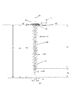
[0007] Fig. 1 shows a side elevation view of one embodiment of a concrete
screw;
[0008] Fig. 2 shows a perspective view of the screw;
[0009] Fig. 3 shows a partial cross-section view of the screw taken along
a plane in
which the screw axis lies;
[0010] Fig. 4 shows a partial side elevation view of the screw;
[0011] Fig. 5 shows a head end axial view of the screw;
[0012] Figs. 6-7 shows another embodiment of a concrete screw;
[0013] Fig. 8-10 show another embodiment of a concrete screw;
[0014] Fig. 11 shows an exemplary symmetric thread profile;
[0015] Fig. 12 shows an exemplary asymmetric thread profile;
[0016] Fig. 13 shows another embodiment of a screw;
[0017] Fig. 14 shows another embodiment of a screw;
[0018] Fig. 15 shows another embodiment of a screw;
[0019] Fig. 16 shows another embodiment of a screw;
[0020] Fig. 17 shows another embodiment of a screw; and
[0021] Fig. 18 shows another embodiment of a screw.
2

CA 03095780 2020-09-30
WO 2019/199430 PCT/US2019/023812
DETAILED DESCRIPTION
[0022] The description below references a concrete screw. However, the
same
screw configuration advantageously provides high resistance to pullout in
hurricane
applications in which the screw may be placed into materials other than
concrete.
[0023] Referring to Figs. 1-5, one embodiment of a concrete screw 10 is
shown.
The concrete screw includes a head end 12, a shank or core 14 and a tapered
end 16. The
head end 12 includes a drive head part 18 and an integrated washer part 20 and
is located at
one end of the shank 14. As used herein the term shank refers to the elongated
core or
shaft of the screw, which can include threaded and unthreaded portions. The
tapered end
16 is located at an opposite end of the shank 14 and terminates in a point or
tip 22. By way
of example, the taper angle al defining the point 22 may be between about
twenty to thirty-
five degrees (such as about twenty-two to thirty degrees).
[0024] A high thread 30 begins on the tapered end 16 (e.g., preferably at
the very
tip or only slightly short of the tip), extends onto the shank 14 and
terminates at an axial
location 32 along the shank. The high thread 30 is a right-hand thread as
shown, and has a
peripheral edge 34 formed where a leading flank 36 meets a trailing flank 38,
which
together define a high thread angle a2 of between about thirty degrees and
about forty-five
degrees (e.g. between 35 and 45 ). In one implementation, the high thread is
symmetric,
with a leading flank angle and a trailing flank angle that are both the same.
[0025] A helical portion or extent 40 of the peripheral edge 34 includes
a plurality
of notches 42 spaced apart from each other in an equidistant manner. Here, the
helical
portion 40 begins on or proximate to the tapered end 16 and extends along the
remainder of
the high thread toward to the axial location 32. By way of example, each
helical turn of the
high thread (i.e., each helical portion of the high thread that extends
through three-hundred
and sixty degrees about the elongated axis 50 of the screw) may include 11
notches 42, but
other variations are possible, including less than 11 notches or more than 11
notches. In
one example, the notches may be formed as substantially V-shaped notches that
are
oriented substantially perpendicular to the thread helix angle a3 of the
thread 30, which
angle a3 may be between about ten degrees and about twenty-five degrees, where
the helix
angle is the cut angle of the thread relative to a plane 44 perpendicular to
the central axis 50
of the thread. In the context of the present application the term "V-shaped"
as used in
relation to thread peripheral edge notches means that the notch is formed as a
V-shaped
3

CA 03095780 2020-09-30
WO 2019/199430 PCT/US2019/023812
recess or cutout along the peripheral edge, which may have a sharp point at
the bottom of
the V-shape, a flat at the bottom of the V-shape or a curvature at the bottom
of the V-shape.
[0026] In the illustrated embodiment, the high thread 30 includes another
helical
portion or extent 46 extending from helical portion or extent 40 toward the
screw tip 22,
where helical portion 46 is completely free of any notches along the
peripheral edge.
However, in other variations the notch arrangement could run substantially the
full length
of the high thread 30.
[0027] The screw 10 has a penetrating axial length LP defined between the
tip 22 of
the tapered end 16 and a location at which the shank 14 meets the head end 12.
An axial
distance DH is defined between the tip 22 of the tapered end 16 and the axial
location 32.
Here, the axial distance DH is at least ninety-five percent of the penetrating
axial length LP
of the screw. However, variations are possible (e.g., distance DH at least
ninety percent of
length LP).
[0028] A low thread 60 begins on the tapered end 16 (e.g., preferably at
the very tip
or only slightly short of the tip), extends onto the shank 14 and terminates
at an axial
location 62 along the shank. Here, the axial location 62 is substantially the
same as the
axial location 32, and an axial length of the low thread is substantially the
same as and
contiguous with the axial length of the high thread. The low thread 30 is a
right-hand
thread as shown, and has a peripheral edge 64 formed where a leading flank 66
meets a
trailing flank 68, which together define a low thread angle a4 of between
about thirty
degrees and about forty-five degrees (e.g. between 35 and 45 ). In one
implementation,
the low thread is symmetric, with a leading flank angle and a trailing flank
angle that are
both the same. Notably, peripheral edge 64 is free of any notches.
[0029] An axial distance DL is defined between the tip 22 of the tapered
end 16 and
the axial location 62. Here, the axial distance DL is at least ninety-five
percent of the
penetrating axial length LP of the screw. However, variations are possible
(e.g., distance
DL at least ninety percent of length LP).
[0030] The pitch PH of the high thread 30 is substantially uniform along
the length
of the thread, as is the pitch PL of the low thread 60, and the low thread
pitch PL is
substantially the same as the high thread pitch PH. Each turn of the low
thread 60 is
located substantially at an axial mid-point between adjacent turns of the high
thread 30.
[0031] The high thread 30 includes a minor diameter Dm and a major
diameter
DM30, and the low thread 60 includes the same minor diameter Dm and a major
diameter
4

CA 03095780 2020-09-30
WO 2019/199430 PCT/US2019/023812
DM60. The height of each thread along the shank 14 is defined as the major
diameter less
the minor diameter. The shank 14 is substantially a right-circular cylinder,
and the cross-
section of the tapered end 16 is circular, where the cross-section lies in any
plane that is
perpendicular to the screw axis 50.
[0032] As mentioned above, the head end 12 includes a drive head part 18
and an
integrated washer part 20. The washer 20 includes a lower surface 70 facing
the tapered
end 16. The lower surface 70 is substantially planar, and lies within a plane
72 that is
substantially perpendicular to the screw axis 50. The washer 20 includes a
periphery 74
that extends outward beyond the periphery 76 of the drive head 18 in axial end
view (Fig.
5). The drive head periphery 76 defines a hex-shape for socket engagement, and
the
washer periphery 74 defines a circular shape. An end face 78 of the drive head
18 include
a drive recess 80 to receive a drive tool. Here the recess is formed with a
star-drive mating
configuration, but other configurations are possible. The washer 20 has an
axial thickness
TW and the drive head 18 has an axial thickness TDH. Here, the axial thickness
TW is less
than thirty percent of axial thickness TDH, but other variations are possible.
[0033] Various implementations of concrete screws in accordance with the
configuration depicted in Figs. 1-5 are possible. By way of example, Tables 1
and 2 below
sets forth various examples of such screw implementations. Typical axial
penetrating
lengths LP for such screws may be in the range of between about one inch and
about five
inches.

CA 03095780 2020-09-30
WO 2019/199430
PCT/US2019/023812
Table 1 - Exemplary Screw Dimensions
(All Ranges in Inches)
Ex. Thread Pitch Dm DM30 DM60 High Low
(PH & PL) Thread Thread
Height Height
1 0.100 - 0.125 0.120 - 0.140 0.190 - 0.145 - 0.055 -
0.010 -
0.210 0.165 0.085 0.035
2 0.120 - 0.140 0.160 - 0.180 0.240- 0.200- 0.070-
0.020 -
0.260 0.215 0.090 0.045
3 0.130 - 0.150 0.215 - 0.245 0.300 - 0.265 - 0.075 -
0.035 -
0.330 0.285 0.105 0.065
4 0.120 - 0.130 0.195 - 0.210 0.270 - 0.225 - 0.070 -
0.020 -
0.290 0.240 0.090 0.040
Table 2 - Exemplary Screw Dimensions
(All Ranges in Inches)
Ex. Thread Pitch Dm DM30 DM60 High Low
(PH & PL) Thread Thread
Height Height
1 0.100 - 0.125 0.126 - 0.133 0.195 - 0.150 - 0.062 -
0.017 -
0.205 0.155 0.079 0.029
2 0.125 - 0.135 0.168 - 0.175 0.248 - 0.203 - 0.073 -
0.028 -
0.253 0.208 0.085 0.040
3 0.135 - 0.145 0.225 - 0.230 0.315 - 0.270 - 0.085 -
0.040 -
0.320 0.275 0.095 0.050
4 0.120 - 0.130 0.200 - 0.205 0.278 - 0.230 - 0.073 -
0.025 -
0.283 0.235 0.087 0.035
[0034] Referring now to Figs. 6 and 7, an alternative embodiment of a
concrete
screw 110 is shown having head end 112, shank 114 and tapered end 116. Screw
110 is
similar in configuration to screw 10 above, but screw 110 includes an
unthreaded shank
part 105 disposed between the axial locations 132 and 162 where the high
thread 130 and
low thread 160 end. Here, the distances DH and DL, which are substantially the
same, may
be at least seventy-five percent of penetrating length LP, but no more than
ninety percent of
the penetrating length LP. The outer diameter of the unthreaded shank part 105
is the same
as, or only slightly smaller than, the major diameter of the low thread 160.
The screw
configuration with unthreaded shank part 105 may be utilized, for example, in
longer
length screw implementations. In some longer embodiments, the unthreaded shank
portion
6

CA 03095780 2020-09-30
WO 2019/199430 PCT/US2019/023812
105 may be substantially longer relative to the overall length of the screw
and the axial
length of the threaded portion of the shank.
[0035] Referring now to Figs. 8-10, an alternative configuration of a
concrete screw
210 is shown having head end 212, shank 214 and tapered end 216. Screw 210 is
similar in
configuration to screw 110 above, but screw 210 includes a flat countersunk
head
configuration rather than a hex washer head configuration. The head end 212
has a
frustoconical tapered portion 215 extending from the unthreaded shank part 205
and
leading to a cylindrical part 217. The frustoconical surface includes a
plurality of nibs 219
formed thereon, each nib extending from the cylindrical part 217 toward the
shank part
205. Various nib configurations are possible. The high and low threads 230 and
260, the
distances DH and DL and the penetrating length LP are also shown, it being
noted that the
penetrating length LP is substantially the entire screw length in the case of
this countersunk
head configuration of the screw 210. Embodiments of the countersunk head screw
configuration that lack the unthreaded shank part 205 are also possible.
[0036] It is to be clearly understood that the above description is
intended by way
of illustration and example only, is not intended to be taken by way of
limitation, and that
other changes and modifications are possible. For example, while certain
relative
dimensions have been provided by example above, variations are possible. In
addition,
while the primary embodiments described above reflect screws in which both the
high
thread and the low thread are symmetric, which, as reflected in Fig. 11 means
that the
leading flank angle ab is equal to the trailing flank angle aa, variations are
possible. In
particular, one or both of the high thread and the low thread of the above-
described screws
could be asymmetric, which, as reflected in Fig. 12, means that the leading
flank angle ab
is different than the trailing flank angle aa. In such cases, it is
contemplated that the
leading flank angle ab will be greater than the trailing flank angle aa as
depicted in Fig. 12.
For example, the leading flank angle ab could be in the range of twenty to
thirty degrees
and the trailing flank angle aa in the range of ten to twenty degrees. Table 3
below reflects
the possible thread combinations:
7

CA 03095780 2020-09-30
WO 2019/199430 PCT/US2019/023812
[0037]
Table 3 ¨ Exemplary Thread Combinations
Ex. Hi Thread Lo Thread
1 Symmetric Symmetric
2 Symmetric Asymmetric
3 Asymmetric Symmetric
4 Asymmetric Asymmetric
[0038] The subject concrete screw has a special geometry combination of
the high
thread and low thread which is a unique design configuration for use in
concrete
applications and construction for both high-strength concrete 6,500 to 8,500
psi (45 to 60
MPa), low-strength concrete 2,500 to 4,000 psi (17 to 28 MPa) and hollow
concrete block.
This new design provides higher pull-out force which is critical in the
structural design for
more holding power and also provides improved pull-out resistance in other
materials,
which is useful in hurricane prone areas.
[0039] The concrete screw has special thread profile for both low thread
and high
thread which reduces diving torque, requiring less effort on the part of
installers. As a
result of the special thread profile, the energy of the typical power drill
battery will be
consumed less and more screws will be drilled per charge.
[0040] The described screw thread form (consistent with the aspects
described
above in the summary and consistent with one or more of the screw dimension
sets
described in Tables 1 and 2 above) can be incorporated into other screws
having a variety
of head configurations). For example, Fig. 13 shows such a screw 300 in the
form of a
male hurricane screw with high and low threads that extend partially along the
shank, a hex
head end and a mating thread at the head end. Fig. 14. shows a female
hurricane screw 310
with high and low threads that extend fully along the shank to the
flange/washer, and a
female hex end. Fig. 15 shows a female hurricane screw 320 with high and low
threads
that extend partially along the shank to a location short of the
flange/washer, and head end
with a mating thread. Fig. 16 shows another variation of a screw 330 with a
hex end. Fig.
17 shows another variation of a screw 340 with a flat countersinking head.
Fig. 18 shows
another male hurricane screw 350 with high and low threads that extend along
the shank all
the way to the flange/washer, a hex head end and a mating thread at the head
end.
8

Representative Drawing
A single figure which represents the drawing illustrating the invention.
Administrative Status

2024-08-01:As part of the Next Generation Patents (NGP) transition, the Canadian Patents Database (CPD) now contains a more detailed Event History, which replicates the Event Log of our new back-office solution.

Please note that "Inactive:" events refers to events no longer in use in our new back-office solution.

For a clearer understanding of the status of the application/patent presented on this page, the site Disclaimer , as well as the definitions for Patent , Event History , Maintenance Fee  and Payment History  should be consulted.

Event History

Description Date
Inactive: Cover page published 2022-06-27
Inactive: Correction certificate - Sent 2022-06-22
Correction Requirements Determined Compliant 2022-06-15
Inactive: Patent correction requested-Exam supp 2022-06-02
Inactive: Grant downloaded 2021-09-15
Letter Sent 2021-09-14
Grant by Issuance 2021-09-14
Inactive: Cover page published 2021-09-13
Inactive: Final fee received 2021-07-28
Pre-grant 2021-07-28
Notice of Allowance is Issued 2021-07-06
Letter Sent 2021-07-06
Notice of Allowance is Issued 2021-07-06
Inactive: Q2 passed 2021-06-29
Inactive: Approved for allowance (AFA) 2021-06-29
Letter Sent 2021-06-18
All Requirements for Examination Determined Compliant 2021-06-09
Request for Examination Received 2021-06-09
Advanced Examination Requested - PPH 2021-06-09
Advanced Examination Determined Compliant - PPH 2021-06-09
Amendment Received - Voluntary Amendment 2021-06-09
Request for Examination Requirements Determined Compliant 2021-06-09
Inactive: Cover page published 2020-11-12
Common Representative Appointed 2020-11-07
Letter sent 2020-10-22
Priority Claim Requirements Determined Compliant 2020-10-15
Inactive: IPC assigned 2020-10-14
Application Received - PCT 2020-10-14
Inactive: First IPC assigned 2020-10-14
Request for Priority Received 2020-10-14
Inactive: IPC assigned 2020-10-14
National Entry Requirements Determined Compliant 2020-09-30
Application Published (Open to Public Inspection) 2019-10-17

Abandonment History

There is no abandonment history.

Maintenance Fee

The last payment was received on 2021-03-19

Note : If the full payment has not been received on or before the date indicated, a further fee may be required which may be one of the following

  • the reinstatement fee;
  • the late payment fee; or
  • additional fee to reverse deemed expiry.

Patent fees are adjusted on the 1st of January every year. The amounts above are the current amounts if received by December 31 of the current year.
Please refer to the CIPO Patent Fees web page to see all current fee amounts.

Fee History

Fee Type Anniversary Year Due Date Paid Date
Basic national fee - standard 2020-09-30 2020-09-30
MF (application, 2nd anniv.) - standard 02 2021-03-25 2021-03-19
Request for examination - standard 2024-03-25 2021-06-09
Final fee - standard 2021-11-08 2021-07-28
MF (patent, 3rd anniv.) - standard 2022-03-25 2022-03-18
Requesting correction of an error 2022-06-02 2022-06-02
MF (patent, 4th anniv.) - standard 2023-03-27 2023-03-17
MF (patent, 5th anniv.) - standard 2024-03-25 2024-03-15
Owners on Record

Note: Records showing the ownership history in alphabetical order.

Current Owners on Record
THE HILLMAN GROUP, INC.
Past Owners on Record
FARHAD LAJEWARDI
Past Owners that do not appear in the "Owners on Record" listing will appear in other documentation within the application.
Documents

To view selected files, please enter reCAPTCHA code :


To view images, click a link in the Document Description column. To download the documents, select one or more checkboxes in the first column and then click the "Download Selected in PDF format (Zip Archive)" or the "Download Selected as Single PDF" button.

List of published and non-published patent-specific documents on the CPD .

If you have any difficulty accessing content, you can call the Client Service Centre at 1-866-997-1936 or send them an e-mail at CIPO Client Service Centre.


Document
Description 
Date
(yyyy-mm-dd) 
Number of pages   Size of Image (KB) 
Description 2020-09-29 8 404
Representative drawing 2020-09-29 1 23
Drawings 2020-09-29 17 253
Claims 2020-09-29 5 171
Abstract 2020-09-29 2 74
Claims 2021-06-08 7 266
Representative drawing 2021-08-18 1 10
Maintenance fee payment 2024-03-14 47 1,943
Courtesy - Letter Acknowledging PCT National Phase Entry 2020-10-21 1 586
Courtesy - Acknowledgement of Request for Examination 2021-06-17 1 437
Commissioner's Notice - Application Found Allowable 2021-07-05 1 576
National entry request 2020-09-29 6 163
Declaration 2020-09-29 2 83
International search report 2020-09-29 1 53
Patent cooperation treaty (PCT) 2020-09-29 1 38
PPH request 2021-06-08 14 507
PPH supporting documents 2021-06-08 6 389
Final fee 2021-07-27 3 81
Electronic Grant Certificate 2021-09-13 1 2,527
Patent correction requested 2022-06-01 11 387
Correction certificate 2022-06-20 2 394