Note: Descriptions are shown in the official language in which they were submitted.
WO 2019/193554 PCT/IB2019/052793
1
PACKAGING MACHINE INFEED, SEPARATION,
AND CREASING MECHANISMS
CROSS-REFERENCE TO RELATED APPLICATIONS
[0001] This application claims priority to United States Patent
Application Serial
No. 16/375,579, filed April 4, 2019, and entitled "Packaging Machine Infeed,
Separation, and Creasing Mechanisms, which claims priority to and the benefit
of:
United States Patent Application Serial No. 62/729,762, filed September 11,
2018, and
entitled "Packaging Machine Infeed, Separation, and Creasing Mechanisms";
Belgian
Patent Application No. 2018/05697, filed October 10, 2018, and entitled
"Packaging
Machine Infeed, Separation and Creasing Mechanisms"; Belgian Patent
Application
No. 2018/05233, filed April 5, 2018, and entitled "Spring-Mounted Blades"; and
Belgian Patent Application No. 2018/05232, filed April 5, 2018, and entitled
"Cutting
Out False Creases".
BACKGROUND
1. Technical Field
[0002] Exemplary embodiments of the disclosure relate to systems,
methods, and
devices for packaging items into boxes. More specifically, exemplary
embodiments
relate to packaging machine mechanisms that feed sheet material into the
packaging
machine, separate the sheet material into lengths used to create packaging
templates,
and form cuts and creases in the sheet material to form packaging templates
therefrom.
2. The Relevant Technology
[0003] Shipping and packaging industries frequently use paperboard and
other
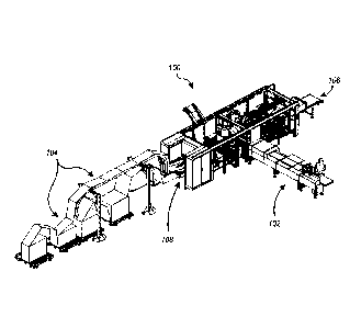
sheet material processing equipment that converts sheet materials into box
templates.
One advantage of such equipment is that a shipper may prepare boxes of
required sizes
as needed in lieu of keeping a stock of standard, pre-made boxes of various
sizes.
Consequently, the shipper can eliminate the need to forecast its requirements
for
particular box sizes as well as to store pre-made boxes of standard sizes.
Instead, the
shipper may store one or more bales of fanfold material, which can be used to
generate
a variety of box sizes based on the specific box size requirements at the time
of each
shipment. This allows the shipper to reduce storage space normally required
for
periodically used shipping supplies as well as reduce the waste and costs
associated
with the inherently inaccurate process of forecasting box size requirements,
as the items
shipped and their respective dimensions vary from time to time.
Date Recue/Date Received 2022-03-16
CA 03096001 2020-10-02
WO 2019/193554 PCT/1B2019/052793
2
[0004] In addition to reducing the inefficiencies associated with storing
pre-made
boxes of numerous sizes, creating custom sized boxes also reduces packaging
and
shipping costs. In the fulfillment industry it is estimated that shipped items
are typically
packaged in boxes that are about 65% larger than the shipped items. Boxes that
are too
large for a particular item are more expensive than a box that is custom sized
for the
item due to the cost of the excess material used to make the larger box. When
an item is
packaged in an oversized box, filling material (e.g., Styrofoam, foam peanuts,
paper, air
pillows, etc.) is often placed in the box to prevent the item from moving
inside the box
and to prevent the box from caving in when pressure is applied (e.g., when
boxes are
taped closed or stacked). These filling materials further increase the cost
associated
with packing an item in an oversized box.
[0005] Customized sized boxes also reduce the shipping costs associated
with
shipping items compared to shipping the items in oversized boxes. A shipping
vehicle
filled with boxes that are 65% larger than the packaged items is much less
cost efficient
to operate than a shipping vehicle filled with boxes that are custom sized to
fit the
packaged items. In other words, a shipping vehicle filled with custom sized
packages
can carry a significantly larger number of packages, which can reduce the
number of
shipping vehicles required to ship the same number of items. Accordingly, in
addition
or as an alternative to calculating shipping prices based on the weight of a
package,
shipping prices are often affected by the size of the shipped package. Thus,
reducing
the size of an item's package can reduce the price of shipping the item. Even
when
shipping prices are not calculated based on the size of the packages (e.g.,
only on the
weight of the packages), using custom sized packages can reduce the shipping
costs
because the smaller, custom sized packages will weigh less than oversized
packages
due to using less packaging and filling material.
[0006] Although sheet material processing machines and related equipment
can
potentially alleviate the inconveniences associated with stocking standard
sized
shipping supplies and reduce the amount of space required for storing such
shipping
supplies, previously available machines and associated equipment have various
drawbacks. For instance, previous systems have focuses primarily on the
creation of
boxes and sealing the boxes once they are filled. Such systems have required
the use of
multiple separate machines and significant manual labor. For instance, a
typical box
forming system includes a converting machine that cuts, scores, and/or creases
sheet
material to form a box template. Once the template is formed, an operator
removes the
template from the converting machine and a manufacturer's joint is created in
the
CA 03096001 2020-10-02
WO 2019/193554 PCT/IB2019/052793
3
template. A manufacturer's joint is where two opposing ends of the template
are
attached to one another. This can be accomplished manually and/or with
additional
machinery. For instance, an operator can apply glue (e.g., with a glue gun) to
one end
of the template and can fold the template to join the opposing ends together
with the
glue therebetween. Alternatively, the operator can at least partially fold the
template
and insert the template into a gluing machine that applies glue to one end of
the
template and joins the two opposing ends together. In either case, significant
operator
involvement is required. Additionally, using a separate gluing machine
complicates the
system and can significantly increase the size of the overall system.
[0007] Once the manufacturer's joint is created, the template can be
partially
erected and bottom flaps of the template can be folded and secured to form a
bottom
surface of a box. Again, an operator typically has to erect the box. The
bottom flaps can
be folded and secured manually by the operator or with the assistance of yet
additional
machines. Thereafter, an operator transfers the to-be-packaged item(s) into
the box and
the top flaps are folded and secured.
[0008] While some efforts have been made to create individual packaging
machines
that create packaging templates and erect and seal the packaging template
around the
to-be-packaged item(s), there remains room for improvement in the area of
packaging
machines and related methods.
BRIEF SUMMARY
[0009] Exemplary embodiments of the disclosure relate to systems,
methods, and
devices for packaging items into boxes. More specifically, exemplary
embodiments
relate to packaging machine mechanisms that feed sheet material into the
packaging
machine, separate the sheet material into lengths used to create packaging
templates,
and form creases and cuts in the sheet material to form packaging templates
therefrom.
[0010] For instance, one embodiment of a packaging machine used to
convert
generally rigid sheet material into packaging templates for assembly into
boxes or other
packaging includes an infeed system. The infeed system directs a first feed of
the sheet
material and a second feed of the sheet material into the packaging machine.
The infeed
system includes a first low friction surface and an associated first
advancement
mechanism. The first advancement mechanism is configured to engage and advance
the
first feed of the sheet material along the first low friction surface and into
the packaging
machine. A second low friction surface and an associated second advancement
mechanism are also included. The second advancement mechanism is configured to
engage and advance the second feed of the sheet material along the second low
friction
CA 03096001 2020-10-02
WO 2019/193554 PCT/IB2019/052793
4
surface and into the packaging machine. The first low friction surface and the
second
low friction surface form an acute angle that is configured to enable the
sheet material
to be advanced into the packaging machine without creating any folds or
creases in the
sheet material. The converting machine also includes one or more converting
tools
configured to perform one or more conversion functions on the sheet material
as the
sheet material moves through the packaging machine, the one or more conversion
functions being selected from the group consisting of creasing, bending,
folding,
perforating, cutting, and scoring, to create the packaging templates.
[0011] According to another embodiment, a packaging machine used to
convert
to generally rigid sheet material into packaging templates for assembly
into boxes or other
packaging includes a separation system that separates the sheet material into
lengths for
use in creating the packaging templates. The separation system includes a
cutting table
having a cutting edge, a first knife, and a second knife. The first knife has
a mounted
end, a free end, and a first knife edge extending at least partially
therebtween. The first
knife edge is angled relative to the cutting edge of the cutting table to
create a contact
point between the first knife edge and the cutting edge of the cutting table
when the
first knife is moved between a raised position to a lowered position. The
second knife
has a mounted end, a free end, and a second knife edge extending at least
partially
therebetween. The second knife edge is angled relative to the cutting edge of
the cutting
table to create a contact point between the second knife edge and the cutting
edge of the
cutting table when the second knife is moved between a raised position to a
lowered
position. The free ends of the first and second knives are positioned adjacent
to one
another near a center of the sheet material. The mounted ends of the first and
second
knives are positioned adjacent to opposing sides of the sheet material.
[0012] According to another embodiment, a packaging machine used to convert
generally rigid sheet material into packaging templates for assembly into
boxes or other
packaging includes a creasing system that forms transverse creases in the
sheet
material. The transverse creases are oriented across the sheet material and
transverse to
the length of the sheet material. The creasing system includes a support plate
that
supports the sheet material, a first creasing roller, and a second creasing
roller. The first
creasing roller is oriented across the sheet material and transverse to the
length of the
sheet material. The first creasing roller has a first creasing ridge extending
radially
therefrom. The first creasing roller is configured to rotate to engage the
first creasing
ridge with the sheet material to form a crease in the sheet material. The
second creasing
roller is oriented across the sheet material and transverse to the length of
the sheet
CA 03096001 2020-10-02
WO 2019/193554 PCT/IB2019/052793
material. The second creasing roller has a second creasing ridge extending
radially
therefrom. The second creasing roller is configured to rotate to engage the
second
creasing ridge with the sheet material to form a crease in the sheet material.
The first
and second creasing rollers are positioned adjacent to one another and are
5 independently operable.
[0013] In another embodiment, a cutting unit for cutting sheet material
includes a
cutting table with a first cutting edge and a blade with a second cutting
edge. The
cutting unit also includes a first actuator mounted between the cutting table
and the
blade for moving the blade relative to the cutting table in an up and downward
cutting
.. movement. The first and the second cutting edges lie at an angle so that a
contact point
can be identified between the first and the second cutting edges during the
cutting
movement. A pressure element is provided to exert a force on the blade to
increase a
pressure between the first cutting edge and the second cutting edge at the
position of
the contact point.
[0014] In another embodiment, a method is provided for cutting sheet
material with
a cutting unit that includes a cutting table with a first cutting edge and a
blade with a
second cutting edge. The first cutting edge and the second cutting edge lie at
an angle
The method includes moving the blade relative to the cutting table in an up
and
downward (linear) cutting movement by means of a first actuator and pressing
on the
blade by means of a pressure element during the cutting movement in order to
increase
a pressure between the first cutting edge and the second cutting edge at the
position of a
contact point.
[0015] In another embodiment, a device for making box templates from a
continuous length of sheet material includes a supply of sheet material, a
cutting
device, a controller, and a sensor. The supply is configured to supply the
continuous
length of sheet material to the cutting device. The cutting device is
configured to cut the
continuous length of sheet material into successive segments on the basis of
input from
the controller in order to make the box templates. The sensor is configured to
detect an
irregularity in the continuous length of sheet material and to transmit a
position of the
.. irregularity to the controller. The controller is provided to activate a
discharge cycle in
the cutting device on the basis of the position of a waste segment in the
continuous
length of sheet material. The discharge cycle is configured to cause the waste
segment
to be cut from the continuous length and discharged.
[0016] In yet another embodiment, a method for creating box templates
from a
continuous length of sheet material is provided. The method includes supplying
the
CA 03096001 2020-10-02
WO 2019/193554 PCT/IB2019/052793
6
continuous length of sheet material to a cutting device. The method also
includes
cutting the continuous length of sheet material into successive segments with
the
cutting device on the basis of an input from a controller in order to make the
box
templates. The method further includes detecting an irregularity at a position
in the
continuous length of sheet material via a sensor and transmitting the position
to the
controller. The method also includes activating a discharge cycle in the
cutting device
on the basis of the position of the irregularity, cutting a waste segment out
of the
continuous length, and discharging the waste segment from the cutting device.
[0017] These and other objects and features of the present disclosure
will become
more fully apparent from the following description and appended claims, or may
be
learned by the practice of the disclosure as set forth hereinafter.
BRIEF DESCRIPTION OF THE DRAWINGS
[0018] To further clarify the above and other advantages and features of
the present
invention, a more particular description of the invention will be rendered by
reference
to specific embodiments thereof which are illustrated in the appended
drawings. It is
appreciated that these drawings depict only illustrated embodiments of the
invention
and are therefore not to be considered limiting of its scope. The invention
will be
described and explained with additional specificity and detail through the use
of the
accompanying drawings in which:
[0019] Figure 1 illustrate an example box template;
[0020] Figure 2 illustrates an example packaging machine used to package
items.
[0021] Figures 3-5 illustrate various cross-sectional views of an infeed
system of
the packaging machine of Figure 2.
[0022] Figures 6 and 7 illustrates elevational and top views of a
separation
mechanism of the packaging machine of Figure 2.
[0023] Figure 8 illustrates a dual roller creasing mechanism of the
packaging
machine of Figure 2.
[0024] Figure 9 illustrates a side view of an example cutting unit
according to an
embodiment of the present disclosure.
[0025] Figure 10 illustrates a top view of the cutting unit of Figure 9.
[0026] Figure 11 illustrates an example device with a cutting unit,
supply and a
controller according to an embodiment of the present disclosure.
[0027] Figure 12 illustrates schematic of an example device for forming
box
templates according to an embodiment of the present disclosure.
[0028] Figure 13 is a top view of the device of Figure 12.
CA 03096001 2020-10-02
WO 2019/193554 PCT/IB2019/052793
7
DETAILED DESCRIPTION OF THE PREFERRED EMBODIMENTS
[0029] The embodiments described herein generally relate to systems,
methods,
and devices for packaging item(s) into boxes. More specifically, the described
embodiments relate to packaging machine mechanisms that feed sheet material
into the
packaging machine, separate the sheet material into lengths used to create
packaging
templates, and form cuts and creases in the sheet material to form packaging
templates
therefrom.
[0030] While the present disclosure will be described in detail with
reference to
specific configurations, the descriptions are illustrative and are not to be
construed as
1() .. limiting the scope of the present disclosure. Various modifications can
be made to the
illustrated configurations without departing from the spirit and scope of the
invention as
defined by the claims. For better understanding, like components have been
designated
by like reference numbers throughout the various accompanying figures.
[0031] Throughout the description and claims, components are described as
being
in specific orientations or relative positions. Such descriptions are used
merely for the
sake of convenience and are not intended to limit the invention. For instance,
a
component may be described as being above or below another component. It will
be
appreciated, however, that the machines, system, and mechanisms may be
oriented in
other ways in some embodiments. As a result, a component that is described as
being
above another component may be positioned below or to the side of the other
component in some embodiments. In some cases, a component that is described as
being positioned "above" or "below" another component may be understood to be
positioned on one side or another of sheet material that is being converted
into
packaging templates.
[0032] As used herein, the terms "box template" and "blank" are used
interchangeably and refer to a substantially flat material that can be folded
into a box-
like shape. Box templates may be made from a stock of sheet material (e.g.,
paperboard, corrugated board, cardboard, etc.). In some cases, the sheet
material is a
fanfold material that has been folded back and forth on itself to form a bail.
A box
template may have notches, cutouts, divides, and/or creases that allow the box
template
to be bent and/or folded into a box. Additionally, a box template may be made
of any
suitable material, generally known to those skilled in the art. For example,
cardboard or
corrugated paperboard may be used as the box template material. A suitable
material
also may have any thickness and weight that would permit it to be bent and/or
folded
into a box-like shape.
CA 03096001 2020-10-02
WO 2019/193554 PCT/1B2019/052793
8
[0033] Figure 1 illustrates one example embodiment of a packaging
template 10.
The packaging template 10 includes cuts (shown in solid lines) and creases
(shown in
dashed lines). As used herein, a crease can be an impression in the sheet
material that
facilitates folding of the packaging template 10 at the location of the
impression.
Alternatively, a crease can also be a partial incision or score, in which the
sheet
material is only partially cut through its full thickness, such that a
weakening of the
sheet material occurs at the location of the partial cut or score.
[0034] The packaging template 10 includes four central panels A, B, C,
and D.
Each of the four central panels is provided to form a wall of a box. In the
configuration
1() from Figure 1, the panel B forms the bottom wall of the box, panels A
and C form
upright walls of the box, and panel D forms the top wall of the box. Figure 1
also shows
how the length 1, width b, and height h of the box result from the dimensions
of the
packaging template 10. Each of the panels A, B, C, and D has two side flaps,
which are
indicated by A ', B', C', and D', respectively. These side flaps are provided
to form the
two side walls of the box. Further, in the present embodiment, a glue flap A"
extends
from panel A. The glue flap A" serves to connect panel A to panel D when
forming the
box.
[0035] In Figure 1, a wedge-shaped piece of material has been cut away
between
adjacent side flaps. This may be advantageous in some cases in the folding of
the side
flaps. Nevertheless, in other embodiments, a box template may be formed in
which the
adjacent side flaps are separated from each other by a single cut rather than
multiple
cuts to remove a wedge of material. For example, the side flaps in box
template 10 can
be formed by a straight cut in the transverse direction of box template 10,
starting at an
edge of the blank and extending toward a central axis of the box template over
a length
equal to the length of the side flaps.
[0036] It will also be appreciated that the side flaps A', B', C' and D'
can be
dimensioned to fully form or partially form the side panels. When the side
panel has
been only partially formed, the side panels will typically have an opening in
the center,
whereby the box is not fully closed. This is advantageous in some situations.
When the
side panel has been fully formed, the side flaps can be adjoining or
overlapping.
Different combinations hereof are also possible. It will also be understood
how a box
template 10 can be created to form a box with predetermined dimensions.
[0037] Reference to box template 10 will be made through the description.
It will
be understood, however, that box template 10 is merely one example box
template that
may be created with the embodiments disclosed herein. Thus, the specific
configuration
CA 03096001 2020-10-02
WO 2019/193554 PCT/IB2019/052793
9
(e.g., number of panels/flaps, proportions, placement of cuts/creases, etc.)
of a box
template is not limited to that shown in Figure 1.
[0038] Attention is now directed to Figure 2, which illustrates an
example
packaging machine 100 used to create and erect packaging templates around to-
be-
packaged item(s). In the illustrated embodiment, item(s) for packaging are
delivered to
the machine 100 via conveyor 102. The dimensions of the item(s) may be
obtained
while the item(s) is/are positioned on the conveyor 102 or before.
[0039] In any event, the item(s) is/are advanced into the packaging
machine 100 on
conveyor 102. The packaging machine 100 creates a box template custom sized
for the
item(s) from sheet material 104. The packaging machine 100 also folds and
secures the
box template around the item(s). The packaged item(s) is/are then advanced out
of the
packaging machine 100 on another conveyor 106.
INFEED MECHANISM
[0040] One common challenge with packaging machines is feeding the sheet
material into the machine. For instance, the infeed mechanisms of some
packaging
machines create folds or creases in the sheet material as the sheet material
is fed into
the packaging machine. The folds or creases can pose problems as the sheet
material
advances through the packaging machine. By way of example, the folds or
creases can
cause the packaging material to get caught or jammed in the packaging machine.
The
folds or creases can also cause the packaging machine to form desired creases
and/or
cuts in the sheet material at undesired locations in the sheet material.
[0041] In the illustrated embodiment, the packaging machine 100 includes
an
infeed mechanism 108 that is designed to feed multiple streams or feeds of
sheet
material into the converting machine 100 without creating undesired folds or
creases in
the sheet material. Additionally, the infeed mechanism 108 does not require a
cassette
changer that moves up or down in order to feed sheet material from different
streams of
sheet material into the packaging machine 100.
[0042] The infeed mechanism 108 is illustrated in Figures 3-5. In some
embodiments, such as that shown in Figure 3, the infeed mechanism 108 includes
a first
track 110 that guides a first feed 112 of sheet material 104 into a first end
of the
package machine 100 and a second track 114 the guides a second feed 116 of
sheet
material 144 into the first end of the package machine 100. The first track
110 and the
second track 114 may each include a generally planar surface upon which the
respective feeds of sheet material can be advanced. Additionally, the first
track 110 and
the second track 114 can include guides 118, 120 that help the first and
second feeds
CA 03096001 2020-10-02
WO 2019/193554 PCT/1B2019/052793
112, 116 of sheet material 104 to lay generally flat upon the planar surface
of the
respective track 110, 114. In some embodiments, the guides 118, 120 can pivot
and can
include one or more wheels that engage the first and second feeds 112, 116 of
sheet
material 104.
5 [0043] As best seen in Figures 4 and 5, the infeed system 108 also
includes a first
low friction surface 122 and associated first advanced mechanism 124. The
first low
friction surface 122 is generally aligned with the planar surface of track
110. The first
advancement mechanism 124 is positioned and configured to engage and advance
the
first feed 112 of sheet material 104 along the first low friction surface 122.
More
10 specifically, the first advancement mechanism 124 may comprise one or
more feed
rollers, pulleys, and/or belts that can rotate and engage the first feed 112.
The first
advancement mechanism 124 may be spaced apart from the first low friction
surface
122 a distance that is equal to or less than the thickness of the first feed
112. The first
low friction surface 122 acts as a support plate for the first feed 112.
Engagement of the
first advancement mechanism 124 with the first feed 112 causes the first feed
112 to
advance along the first low friction surface 122 and into the packaging
machine 100.
[0044] The infeed system 108 also includes a second low friction surface
126 and
associated second advancement mechanism 128. The second low friction surface
126 is
generally aligned with the planar surface of track 114. The second advancement
mechanism 128 is positioned and configured to engage and advance the second
feed
116 of sheet material 104 along the second low friction surface 126. More
specifically,
the second advancement mechanism 128 may comprise one or more rollers, pulleys
and/or belts that can rotate and engage the second feed 116. The second
advancement
mechanism 128 may be spaced apart from the second low friction surface 126 a
distance that is equal to or less than the thickness of the second feed 116.
The second
low friction surface 126 acts as a support plate for the second feed 116.
Engagement of
the second advancement mechanism 128 with the second feed 116 causes the
second
feed 116 to advance along the second low friction surface 126 and into the
packaging
machine 100.
[0045] In some embodiments, the first and second advancement mechanisms
124,
128 are activated independent from one another. For instance, either the first
advancement mechanism 124 can be activated to advance the first feed 112 into
the
converting machine 100, or the second advancement mechanism 128 can be
activated
to advance the second feed 114 into the converting machine 100. In such an
embodiment, sheet material 104 from only one of the first feed 112 and the
second feed
CA 03096001 2020-10-02
WO 2019/193554 PCT/1B2019/052793
11
114 is advanced into the converting machine 100 at a time. This allows for a
desired
type of sheet material 104 (e.g., size, thickness, color, strength, etc.) to
be selected and
advanced into the packaging machine 100 as needed.
[0046] As can be seen in Figure 5, the first low friction surface 122 and
the second
the friction surface 126 form an acute angle 0 with one another. In the
illustrated
embodiment, the vertex of the angle 0 is formed by second ends of the first
and second
low friction surfaces 122, 126. First ends of the first and second low
friction surfaces
122, 126 are disposed closer to a first end of the packaging machine 100 where
the
sheet material 104 enters the converting machine 100 and the second ends
thereof are
disposed closer to an opposing second end of the converting machine 100. The
angle 0
is small enough to enable the sheet material 104 to be advanced into the
converting
machine 100 without creating any folds or creases in the sheet material 104.
For
instance, in some embodiments the angle 0 is less than about 15 , 12.5 , 10 ,
7.5 , 5 ,
3 , or 2 . The relatively small angle 0 orients the sheet material 104 so that
as the sheet
material 104 advances into tracks 130 of the packaging machine 100, the sheet
material
104 does not bend enough to create an undesirable fold or crease therein.
Additionally,
the relatively small angle 0 allows for either feed 112, 114 of the sheet
material 104 to
be advanced into the packaging machine 100 without requiring adjustment,
repositioning, or reorientation of the infeed mechanism 108.
[0047] While the first and second low friction surfaces 122, 126 form the
angle 0,
the specific configuration of how the angle 0 is formed can vary from one
embodiment
to the next. For instance, in the illustrated embodiment the second low
friction surface
126 is generally parallel with horizontal and/or a feeding direction of the
sheet material
104 through the packaging machine 100, while the first low friction surface
122 is
angled up from the second low friction surface 126 (and horizontal and/or the
feeding
direction of the sheet material 104 through the packaging machine 100). In
other words,
the first end of the first low friction surface 122 is spaced further from the
second low
friction surface 126 than the second end of the first low friction surface
122.
[0048] In other embodiments, however, the first low friction surface 122
may be
generally parallel with horizontal and/or the feeding direction of the sheet
material 104
through the packaging machine 100 and the second low friction surface 126 may
be
angled down from the first low friction surface 122 (and horizontal and/or the
feeding
direction of the sheet material 104 through the packaging machine 100). In
still other
embodiments, the first and second low friction surfaces 122, 126 may both be
angled
relative to horizontal and/or the feeding direction of the sheet material 104
through the
CA 03096001 2020-10-02
WO 2019/193554 PCT/1B2019/052793
12
packaging machine 100. For instance, the first low friction surface 122 may be
angled
up from horizontal and/or the feeding direction of the sheet material 104
through the
packaging machine 100 and the second low friction surface may be angled down
from
horizontal and/or the feeding direction of the sheet material 104 through the
packaging
machine 100.
[0049] In some instances, the first and second low friction surfaces 122,
126 may
be angled away from horizontal and/or the feeding direction of the sheet
material 104
through the packaging machine 100 by an equal and opposite amount (e.g., +2.5
and -
2.5 ). In other instances, the first and second low friction surfaces 122, 126
may be
angled away from horizontal and/or the feeding direction of the sheet material
104
through the packaging machine 100 by different amounts (e.g., +3.5 and -1.5
).
[0050] In still other embodiments, the first and second low friction
surfaces 122,
126 may be oriented generally parallel to one another. In such a case, the
first and
second low friction surfaces 122, 126 may be spaced apart by a small enough
distance
to enable the sheet material to be advanced into the packaging machine without
creating any folds or creases in the sheet material and with limited or no
repositioning
of the infeed system. In some cases, the first and second low friction
surfaces 122, 126
may be spaced apart by a distance of about 4 inches or less, about 3 inches or
less,
about 2.5 inches or less, about 2 inches or less, about 1.5 inches or less,
about 1 inch or
less, about .75 inches or less, about .5 inches or less, about .25 inches or
less, about .1
inches or less.
[0051] It will be appreciated that other aspects of the first and second
low friction
surfaces 122, 126 can vary from one embodiment to the next. For instance, in
the
illustrated embodiment, the first and second low friction surfaces 122, 126
are formed
of distinct components that are connected together or positioned adjacent to
one
another. In other embodiments, however, a single component may be formed with
the
first and second low friction surfaces 122, 126 disposed on opposing sides
thereof
[0052] Regardless of the specific orientations of the first and second
low friction
surfaces 122, 126, the first and second advancement mechanisms 124, 128 may be
oriented so as to engage the first and second feeds 112, 114, respectively, to
advance
the first and second feeds 112, 114 along the first and second low friction
surfaces 122,
126. For instance, as shown in Figures 4 and 5, the orientation of the first
advancement
mechanism 124 generally corresponds to the orientation of the first low
friction surface
122 and the orientation of the second advancement mechanism 128 generally
corresponds to the orientation of the second low friction surface 126.
CA 03096001 2020-10-02
WO 2019/193554 PCT/1B2019/052793
13
[0053] Furthermore, as can be seen in the Figures, the first advancement
mechanism 124 is positioned above the first low friction surface 122.
Additionally, the
second low friction surface 126 is positioned below the first low friction
surface 122.
As a result, the second low friction surface 126 and the first advancement
mechanism
124 are positioned on opposite sides of the first low friction surface 122.
Similarly, the
second advancement mechanism 128 is positioned below the second low friction
surface 126. As a result, the second advancement mechanism 128 and the first
low
friction surface 122 are positioned on opposite sides of the second low
friction surface
126.
to SEPARATION MECHANISM
[0054] Once the sheet material 104 is advanced into the packaging machine
100,
the sheet material 104 needs to be cut or separated into lengths that can be
used to form
individual packaging templates. Rolling knives are typically used for cutting
the sheet
material. One advantage to rolling knives is their reliability. However, a
disadvantage
of rolling knives is that the cutting speed is relatively slow because the
rolling knives
have to move across the sheet material to make the cuts. Because of the
relatively low
cutting speed of rolling knives, the throughput of packaging machines
incorporating
them is lower than desired.
[0055] Figures 6 and 7 illustrate elevational and top views of a
separation
mechanism 140 that can be used to separate the sheet material 104 into lengths
for
packaging templates. The separation mechanism 140 includes knives that cut the
sheet
material 104 through an upward and downward cutting movement. As used herein,
"upward and downward cutting movement" is not limited to movements within a
vertical plane. Rather, "upward and downward cutting movement" generally
refers to
the knives moving towards and away from the sheet material 104 in order to
create a
cut therein. Thus, movement of the knives through diagonal and/or horizontal
planes
can be considered upward and downward cutting movements so long as the knives
are
moving towards and away from the sheet material 104 being cut. Upward and
downward cutting movements of the knives is also referred to herein as moving
the
knives between non-activated and activated positions.
[0056] An upward and downward cutting movement is advantageous because it
is
easily controllable. Another advantage is that one up and down cutting
movement can
be very short and less time consuming compared to rolling knives. Furthermore,
the
upward and downward cutting movement is performed relative to a cutting table.
The
cutting table is an element that serves as support for the sheet material
while the knives
CA 03096001 2020-10-02
WO 2019/193554 PCT/1B2019/052793
14
cut the sheet material. As a result, the sheet material will not undesirably
move during
the cutting movement of the knives. The cutting table also serves as the
counter knife of
the knives. This means that the cutting table can exert a counterforce to the
force that
the knives exert on the sheet material. As a result, the sheet material will
not move with
the downward movement of the knives.
[0057] With more specific reference to Figure 6, the separation mechanism
140 is
illustrated in an elevational view. As can be seen, the separation mechanism
140
includes a cutting table 142. The cutting table 142 has a top surface that
supports the
sheet material 104 after the sheet material is advanced past the infeed
mechanism 108.
The cutting table 142 also includes a cutting edge 144, which as discussed in
further
detail below helps facilitate cutting of the sheet material 104.
[0058] The separation mechanism 140 also includes first and second knives
146,
148. The first knife 146 has a mounted end 150, a free end 152, and a first
knife edge
154 extending at least partially therebtween. Similarly, the second knife 148
has a
mounted end 156, a free end 158, and a second knife edge 160 extending at
least
partially therebtween. The free ends 152, 158 of the first and second knives
146, 148
are positioned adjacent to one another above the sheet material 104. For
instance, in
some embodiments, the free ends 152, 158 of the first and second knives 146,
148 are
spaced apart by less than 1.0 inches, 0.75 inches, 0.5 inches, 0.25 inches, or
0.1 inches.
Furthermore, in some embodiments, the free ends 152, 158 are disposed
generally
above the center of the sheet material 104. The mounted ends 150, 156 of the
first and
second knives 146, 148 are positioned adjacent to opposing sides of the sheet
material
104.
[0059] The mounted ends 150, 156 of the first and second knives 146, 148
are
connected to tracks 162, 164, respectively. The connections between the
mounted ends
150, 156 and the tracks 162, 164 are movable to enable the first and second
knives 146,
148 to be raised and lowered or moved towards and away from the sheet material
104.
Additionally, the first and second knives 146, 148 are associated with one or
more
actuators 166 (e.g., motor, spring, cylinder, etc.) to move the knives 146,
148 between
the raised and lowered positions. In some embodiments, the one or more
actuators 166
associated with the knives 146, 148 simultaneously move the first and second
knives
146, 148 between the non-activated and activated positions. In other
embodiments, the
one or more actuators 166 may be enabled to move the first and second knives
146, 148
independently between the non-activated and activated positions.
CA 03096001 2020-10-02
WO 2019/193554 PCT/1B2019/052793
[0060] The cutting edge 144 of the cutting table 142 and the first and
second knives
146, 148 may be configured to cooperate to cut the sheet material 104. For
instance, the
first and second knives 146, 148 may be sized, shaped, positioned, and/or
oriented
relative to the cutting edge 144 to enable the cutting edge 144 and the first
and second
5 knife edges 154, 160 to efficiently cut the sheet material 104 when the
first and second
knives 146, 148 are moved from the non-activated position to the activated
position.
[0061] By way of example, the first and second knife edges 154, 160 may
each be
angled relative to the cutting edge 144 of the cutting table 142 to create a
contact point
between the first knife edge 154 and the cutting edge 144 and between the
second knife
10 edge 160 and the cutting edge 144. More specifically, the cutting edge
144 of the
cutting table 142 lies within a plane and the first and second knife edges
154, 160 may
be angled towards and/or across the plane of the cutting edge 144. In some
embodiments, the first knife edge 154 is angled relative to the cutting edge
144 of the
cutting table 142 such that the mounted end 150 of the first knife 146 is
disposed on a
15 first side of the plane and the free end 152 of the first knife 146 is
disposed on a second
side of the plane. Similarly, the second knife edge 160 may be angled relative
to the
cutting edge 144 of the cutting table 142 such that the mounted end 156 of the
second
knife 148 is disposed on the first side of the plane and the free end 158 is
disposed on
the second side of the plane.
[0062] In some embodiments, the separation mechanism 140 includes a biasing
member associated with each of the first and second knives 146, 148 to bias or
maintain
the first and second knives 146, 148 against the cutting edge 144. For
instance, Figure 7
illustrates a top view of the first knife 146. As can be seen, the mounted end
150 of the
first knife 146 may mounted (pivotally or at an angle) so that the first knife
146 is
angled towards the cutting edge 144. Additionally, a biasing member 168
applies a
force to the first knife 144 to ensure that the first knife 146 contacts the
cutting edge
144 with sufficient force so that the first knife 146 and the cutting edge 144
can cut the
sheet material 104. Furthermore, the biasing member 168 ensures that the
single
moving contact point between the first knife edge 154 and the cutting edge 144
is
consistent even when the edges are not all perfectly straight. As a result,
the biasing
member 168 reduces the need for expensive tolerances in the components. The
second
knife 148 can include a similar biasing member. The biasing members may
include
springs, cylinders, motors, etc.
[0063] In addition to the first and second knives 146, 148 being angled
towards the
cutting edge 144 (e.g., the free ends 152, 158 being disposed closer to the
cutting edge
CA 03096001 2020-10-02
WO 2019/193554 PCT/1B2019/052793
16
144 than the mounted ends 150, 156), the first and second knives can also
taper from
the mounted ends 150, 156 toward the free ends 152, 158, such that the first
and second
knife edges 154, 160 are angled in two directions relative to the cutting edge
144 of the
cutting table 142. For instance, the first knife edge 154 has a first end
adjacent to the
mounted end 150 and a second end adjacent to the free end 152, and the second
end is
disposed vertically higher than the first end. In other words, the first knife
146 has a
non-cutting edge opposite to the first knife edge 154 and the second end of
the first
knife edge 154 is positioned closer to the non-cutting edge than the first end
of the first
knife edge 154. Similarly, the second knife edge 160 has a first end adjacent
to the
mounted end 156 and a second end adjacent to the free end 158, and the second
end is
disposed vertically higher (or closer to a non-cutting edge) than the first
end.
[0064] As a result of the angled configurations of the first and second
knives 146,
148, the contact points between the first knife edge 154 and the cutting edge
144 and
between the second knife edge 160 and the cutting edge 144 move across the
cutting
edge 144 as the first and second knives are moved between the non-activated
and
activated positions. Because the first and second knife edges 154, 160 are
configured as
essentially mirror images of one another, when the contact point between the
first knife
edge 154 and the cutting edge 144 moves across the cutting edge 144 in a first
direction, the contact point between the second knife edge 160 and the cutting
edge 144
moves across the cutting edge 144 in a second direction that is opposite to
the first
direction. Nevertheless, it will be appreciated that the first and second
knives may not
be mirror images of one another. In such cases, the contact points may move is
the
same direction when the first and second knives are moved between the non-
activated
and activated positions.
CREASING MECHANISMS
[0065] As the sheet material 104 advances through the converting machine
100,
various cuts and creases are formed in the sheet material 104 in order to
transform the
sheet material into packaging templates, such as packaging template 10 shown
in
Figure 1. One challenge with making packaging templates, such as packaging
template
10, is forming the transverse creases between the panels A, B, C, and D.
Typically, a
creasing tool is moved transversely across the sheet material to form the
creases.
Similar to the rolling knives discussed above, moving a creasing tool
transversely
across the sheet material can be relatively slow, thereby reducing the
throughput of the
packaging machine. Additionally, transversely moving creasing tools require
the sheet
material to be stationary when forming the creases, otherwise the creases
would be
CA 03096001 2020-10-02
WO 2019/193554 PCT/1B2019/052793
17
formed at angles or the creasing tools would have to be able to move both
transversely
and longitudinally to crease transverse creases.
[0066] Figure 8 illustrates a creasing system 180 that can be used to
form
transverse creases in the sheet material 104 in a consistent and rapid manner.
The
creasing system 180 includes a support plate 182 that supports the sheet
material 104 as
the sheet material moves through the packaging machines 100. The creasing
system
180 also includes a first creasing roller 184 that is oriented across the
sheet material
104 and transverse to the length of the sheet material 104. The first creasing
roller 184
has a body 186 with a predetermined diameter. In the illustrated embodiment,
the body
186 is cylindrical, but the body 186 could have other shapes A first creasing
ridge 188
extends radially from the cylindrical body 186. The first creasing ridge 188
may be
integrally formed with the cylindrical body 186 or may include an insert that
is attached
to the body 186 or received within a recess in the body 186 and extends
therefrom.
[0067] The first creasing roller 184 is configured to rotate about its
axis to engage
the first creasing ridge 188 with the sheet material 104 to form a crease in
the sheet
material 104. The support plate 182 provides a counter pressure to the first
creasing
roller 184 to enable the first creasing ridge 188 to form a crease in the
sheet material
104.
[0068] The distance between the support plate 182 and the outer surface
of the
cylindrical body 186 may be about the same as or greater than the thickness of
the sheet
material 104. As a result, when the first creasing roller 184 is rotated so
the first
creasing ridge 188 is not oriented towards the sheet material 104 (as shown in
Figure
8), the sheet material 104 can move between the first creasing roller 184 and
the
support plate 182 without any creases being formed therein.
[0069] In contrast, when the outer radial surface of the first creasing
ridge 188 is
oriented towards the support plate 182, the distance therebetween is less than
the
thickness of the sheet material 104. As a result, the sheet material 104 can
be positioned
between the first creasing roller 184 and the support plate 182 without being
significantly affected until the first creasing roller 184 is rotated so the
first creasing
ridge 188 is oriented towards the support plate 182. When the first creasing
roller 184 is
rotated so the first creasing ridge 188 is oriented towards the support plate
182, the first
creasing ridge 188 will engage the sheet material 104 and the sheet material
104 will be
compressed between the first creasing ridge 188 and the support plate 182,
thereby
forming a crease in the sheet material 104.
CA 03096001 2020-10-02
WO 2019/193554 PCT/1B2019/052793
18
[0070] In some embodiments, the creasing system 180 also includes a
second
creasing roller 190 that can be substantially similar to the first creasing
roller 184. For
instance, the second creasing roller can include a body 192 and a second
creasing ridge
194. The second creasing ridge 194 may be integrally formed with the body 192
or may
include an insert that attached to the body 192 or received within a recess in
the body
192 and extends therefrom. The second creasing roller 190 can be configured to
rotate
to engage the second creasing ridge 194 with the sheet material 104 to form a
crease in
the sheet material 104, as shown in Figure 8. In still other embodiments, the
creasing
system 180 may include three or more creasing rollers.
[0071] In embodiments that include two or more creasing rollers 184, 190,
at least
the first and second creasing rollers 184, 190 may be positioned adjacent to
one
another. For instance, the first and second creasing rollers 184, 190 may be
spaced
apart (in the feeding direction of the sheet material) by less than 24 inches,
less than 18
inches, less than 12 inches, less than or 6 inches, or the like. The
relatively close
spacing of the first and second creasing rollers 184, 190 can limit the size
of the
creasing system 180 as well as allow for creases to be formed close together
in the
sheet material 104.
[0072] The first and second creasing rollers 184, 190 (or additional
creasing rollers)
may be operated in a variety of ways. For instance, the first and second
creasing rollers
184, 190 may be operated independent from one another. By way of example, the
first
creasing roller 184 may be rotated to form a crease in the sheet material 104
while the
second creasing roller 190 remains disengaged from the sheet material 104, or
vice
versa. Alternatively, the first and second creasing rollers 184, 190 may be
configured to
simultaneously engage the sheet material 104 to simultaneously form multiple
creases
therein In still other embodiments, the first and second creasing rollers 184,
190 may
be configured to alternatingly engage the sheet material 104 to form creases
therein. By
alternating between the first and second creasing rollers 184, 190, the rate
at which the
transverse creases can be formed in the sheet material 104 can be
significantly
increased.
[0073] In some embodiments, the creasing system 180 or the packaging
machine
100 includes a feeding mechanism 196 that is configured to feed the sheet
material 104
through the packaging machine 100. The creasing system 180 can be configured
to
form creases in the sheet material 104 while the sheet material 104 is moving
through
the packaging machine 100. In other words, the sheet material 104 does not
have to
stop moving through the packaging machine 100 in order to allow for the
transverse
CA 03096001 2020-10-02
WO 2019/193554 PCT/1B2019/052793
19
creases to be formed. Rather, the creasing roller(s) can rotate into
engagement with the
sheet material 104 to form creases therein while the sheet material 104
continues to
move through the packaging machine 100 (via the feeding mechanism 196).
CUTTING MECHANISMS
[0074] As noted above, in addition to making creases in the sheet material
104, cuts
can be formed in the sheet material 104 in order to make box templates, such
as box
template 10. For instance, cuts may be formed in the sheet material 104 in
order to
separate adjacent flaps from one another. Figures 9 and 10 illustrate
elevation and top
views, respectively, of a cutting unit 200 that may be used to form cuts in
the sheet
.. material 104.
[0075] In the illustrated embodiment, the cutting unit 200 includes a
blade 202 and
a cutting table 204. The blade 202 may be a guillotine type blade. For
instance, the
blade 202 may perform an up and downward movement 206, also known as a falling
movement. The construction of the blade 202 may be relatively simple. For
instance,
the blade 202 may be a straight guillotine blade. The blade 202 may include
one or
more parts, including, for instance, a mounting segment 208 and cutting
segment 210.
[0076] The blade 202 may be manufactured from a metal or from stainless
steel.
Alternatively, the blade can also be made from a ceramic material or another
hard,
sharp material.
[0077] The cutting table 204 can serve as counter-blade to the blade 202,
serving
for a good operation of the cutting unit. The cutting table 204 may be
straight along a
cutting edge 212, whereby the blade 202 is able to slide with a cutting edge
214 thereof
along the cutting edge 212 of the cutting table 204. The blade 202 may be
placed for
this purpose at an angle a relative to the cutting table. The angle a
introduces a contact
.. point between the cutting edge 212 of the cutting table 204 and a cutting
edge 214 of
the blade 202. This cutting point can be identified and is formed by the
contact point
between the first and the second cutting edges 212, 214. The contact point is
only
visible when the cutting edges 212, 214 intersect. This happens during each
cutting
movement 206. This means that the blade 202 and the cutting table 204 are
positioned
or placed such that an angle a is formed between the first and the second
cutting edges
212, 214. The effective cutting of the sheet material 104 takes place at the
position of
the contact point. Another name for the contact point is the cutting point.
This effective
cutting can be explained with reference to Figure 9.
[0078] Figure 9 shows the blade 202 in a position above the cutting table
204. This
.. is why there is no contact point yet in Figure 9. The blade 202 and the
cutting table 204
CA 03096001 2020-10-02
WO 2019/193554 PCT/IB2019/052793
lie too far apart, so that the cutting edges 212, 214 do not intersect. When
the blade 202
of Figure 9 is moved downward by actuator 216, a contact point will result at
a
determined moment during the cutting movement. In Figure 9 this contact point
results
on the right-hand side of the blade 202. Alternatively, in another embodiment,
it is
5 possible for this to occur on the left-hand side of the blade. This is
for instance possible
by having the blade incline from the other side. This contact point, or
cutting point,
moves during each movement 206 of the blade 202. This means that the position
of the
contact point moves over the cutting edge 212 of cutting table 204 over a
determined
distance during the cutting movement 206. In Figure 9, this displacement of
the contact
10 point goes from the right to the left. This displacement of the contact
point is a function
of the position of the blade 202. In the case that the blade 202 is a straight
blade, this
displacement is directly proportional to the position of the blade 202.
[0079] The cutting table 204 may be flat along an upper side 218, whereby
the
sheet material 104 can advance over this flat upper side 218. This upper side
218 may
15 be smooth so that the sheet material 104 can advance without appreciable
resistance.
Alternatively, the cutting table 204 may take the form of a blade with a sharp
edge,
which is provided at a distance from a sliding surface (not shown). This
sliding surface
fulfils the function of supporting the sheet material 104, similarly to the
flat upper side
218 of the cutting table 204 in Figure 9. The blade with the sharp edge serves
as
20 counter-blade to the blade. The sharp edge of the blade servers here as
cutting edge
212. The blade is controlled by an actuator 216. This actuator 216 ensures
that the
blade 202 is able to perform an up and downward cutting movement 206 relative
to the
cutting table 204. This cutting movement 206 may be a linear movement. The
actuator
can for instance be a pneumatic or an electromechanical actuator. The movement
of the
actuator 216 may be a linear movement in the up and downward direction 206.
[0080] Figure 10 shows a pressure element 220 which is provided to exert
a force F
on the blade 202. More particularly, this force is directed such that a
pressure between
the first and the second cutting edges 212, 214 can be increased. As a result,
the
distance 222 between the blade 202 and the cutting table 204 is reduced.
Figure 10
further shows that the pressure element 220 is placed at a distance from a
hinge element
224. This pressure is thereby increased by having the hinge element 224 exert
a
counter-force to the force F, wherein a torque F' is induced. This torque F'
ensures the
contact between the first and the second cutting edge 212, 214 at a contact
point, which
coincides with the cutting point. More particularly, because the blade 202 is
pushed
CA 03096001 2020-10-02
WO 2019/193554 PCT/1B2019/052793
21
against the cutting table 204, it will increase the pressure on the contact
point between
the cutting table 204 and the blade 202.
[0081] The hinge element 224 can be hinged round an upward axis 226 so
that the
blade 202 can be rotated so that it lies closer against or further from the
cutting table
204. In other words, a distance 222 between the blade 202 and the cutting
table 204 is
adjustable. This may be important for a good operation of the cutting unit.
When the
blade 202 performs a downward movement 206 close to the cutting table 204, the
cutting table 204 will serve more effectively as a counter-blade.
[0082] In an alternative embodiment, which is not shown, a pressure
element can
be embodied as a torque spring in the hinge element 224. As a further
alternative,
pressure element can be embodied as a pneumatic cylinder or a spring.
[0083] During use, the blade 202 moves relative to the counter-blade 212,
whereby
the sheet material 104 is cut at the position the cutting edge 214 contacts
the cutting
edge 212 of the cutting table 204. The blade 202 may lie at an angle a so that
the
cutting edges 212, 214 of the blade 202 and the cutting table 204 come into
contact
only over a minimal area, this contact area being related to the cutting
point. The effect
of pressure element 220 relates to this contact area. Due to the cutting
movement 206,
the blade 202 undergoes undesired effects such as vibration and bending. This
contact
area can be ensured by having the pressure element 220 press on the blade 202.
[0084] From the foregoing, it will be appreciated that the cutting
mechanisms
shown in Figures 9 and 10 may be similar or identical to the separation
mechanism 140
of Figures 6 and 7, or vice versa. For instance, the configuration of the
blades, cutting
table, operation, functions, etc. from the embodiments may be similar or
identical to
one another. Likewise, aspects shown or described in connection with one
embodiment
may be incorporated into the other embodiment.
[0085] Figure 11 shows a schematic top view of a converting assembly 230
that
may be incorporated into the packaging machine 100 for converting sheet
material 104
into box templates. The converting assembly 230 of Figure 11 has an inlet 232,
shown
at the top of the Figure and an outlet 234 shown at the bottom of the figure.
At the
position of the inlet 232, the sheet material 104 is supplied as a continuous
length. At
the outlet 234, a resulting box template exits the converting assembly 230.
[0086] The converting assembly 230 is configured to partition a
continuous length
of the sheet material 104 which enters the converting assembly 230 via inlet
232,
wherein each segment is provided to create a box template. The converting
assembly
230 is further configured to provide each segment with cuts, for instance for
creating
CA 03096001 2020-10-02
WO 2019/193554 PCT/IB2019/052793
22
the side flaps in the box template, and for providing creases (e.g., to define
panels
thereof). It will be apparent that the continuous length can be supplied via
inlet 232 in
continuous manner, i.e. the speed at which the sheet material 104 enters is
substantially
constant, or in discontinuous manner, i.e. the speed at which sheet material
104 enters
is not constant. When the sheet material 104 is supplied in a discontinuous
manner, the
sheet material 104 can, for instance, be stopped regularly. These stops of the
sheet
material 104 may be synchronized with one or more cutting units 236. The
cutting units
236 can then make an incision in the sheet material 104 while the sheet
material 104 is
stationary. This allows the cutting units 236 to be given a fixed position, as
seen in the
Jo direction of movement 238 of the converting assembly 230. When the sheet
material
104 is supplied continuously, the cutting units 236 may be placed on a slide
which can
make a cutting unit 236 move synchronously with the sheet material 104 in the
direction of movement 238 during cutting. Using such slides, it is possible to
cut the
sheet material 104 while stationary and to make a plurality of cuts at
different
longitudinal positions of the sheet material 104. Because the relative
position of the
cutting unit 236 and the sheet material 104 is relevant, combinations of the
above will
also be possible, and it is possible to work with one or more cutting units
236.
[0087] The converting assembly 230 may also include the following
components:
longitudinal blades 240, longitudinal creasing wheels 242, transverse creasing
rollers
244 (which may be similar or identical to the creasing system 180 discussed
above),
and cutting units 236. It will be apparent that the order of these different
components
can be changed in different ways without having an adverse effect on the
essential
operation of the machine. The cutting units 236 can here, for instance, be
provided at
inlet 232 in order to cut the continuous length of sheet material 104 into
segments, after
which the different segments are further processed individually. Discharge 244
may be
placed downstream of a cutting unit 236 which is provided to cut the
continuous length
of sheet material 104 into segments. This is further elucidated below.
[0088] The longitudinal blades 240 may be formed as discs having
peripheral edges
which are formed as blades for cutting the sheet material 104. The discs may
be placed
on a shaft extending transversely over the sheet material 104. The discs may
be
displaceable in the transverse direction. The discs may be displaceable in the
transverse
direction by means of an actuator and the transverse position of the discs may
be
adjustable by a controller 246. This allows different segments of the sheet
material 104
to be cut to different widths. This makes it possible to manufacture box
templates of
CA 03096001 2020-10-02
WO 2019/193554 PCT/IB2019/052793
23
different widths one after the other using the converting assembly 230.
Alternatively,
the longitudinal blades 240 can be placed on several transverse shafts.
[0089] Similar to the longitudinal blades 240, the longitudinal creasing
wheels 242
may be placed on a transverse shaft. The longitudinal creasing wheels 242 may
also be
positioned in the transverse direction via an actuator, wherein the position
is controlled
by the controller 246. This allows the longitudinal creases in successive
segments to be
formed at different transverse positions. Successive box templates can hereby
have
different fold lines.
[0090] Two transverse creasing rollers 244 may be arranged adjacently of
each
other, as seen in the direction of movement. The transverse creasing rollers
244 may
take a substantially identical form and may be individually controllable by
the
controller 246. Each transverse creasing roller 244 may take the form of a
cylindrical
body with a predetermined diameter. Provided on the cylindrical body is a
protrusion
extending over substantially the whole length of the cylindrical body. This
protrusion is
provided to make an impression in the sheet material 104 by means of the
protrusion
when the sheet material 104 passes under the creasing roller 244 and when the
cylindrical body rotates. Provided for this purpose under the creasing rollers
244 is a
counterpressure element, which may take the form of a plate. The distance
between the
plate and the cylindrical surface is here equal to or greater than the
thickness of the
sheet material 104, and the distance between the top of the protrusion on the
cylindrical
surface and the plate, when the protrusion is at its position closest to the
plate, is
smaller than the thickness of the sheet material 104. The sheet material 104
will thus be
able to pass under the creasing roller 244 without being significantly
affected thereby,
until the protrusion is rotated so as to realize an impression in the
cardboard.
[0091] It will also be understood how a transverse creasing roller 244 can
be
controlled to form a transverse crease in the sheet material 104 at a
predetermined
position. Because two transverse creasing rollers 244 are provided, two
transverse
creases can be provided close to each other in the cardboard without the
throughfeed of
the sheet material 104 through the converting assembly 230 having to be slowed
down.
It will be appreciated that when two transverse creases have to be provided
close to
each other in the sheet material 104 and only one transverse creasing roller
244 were to
be provided, throughfeed of the sheet material 104 would have to be stopped in
order to
give the one transverse creasing roller 244 time to perform a full rotation so
as to be
able to rotate the protrusion up to the sheet material 104 once again. Two
transverse
CA 03096001 2020-10-02
WO 2019/193554 PCT/IB2019/052793
24
creasing rollers 244 provide a solution to this slowing down, allowing the
throughfeed
to be high.
[0092] In some embodiments, the converting assembly includes a plurality
of
cutting units 236a, 236a', 236b, 236b', 236c, 236c'. This plurality of cutting
units 236a,
236a', 236b, 236b', 236c, 236c' may be positioned two by two adjacently of
each
other, as seen in the direction of movement. This plurality of cutting units
236a, 236a',
236b, 236b', 236c, 236c' may be connected to the controller 246. A good co-
action of
the different cutting units can thus be guaranteed. As a result, the plurality
of cutting
units 236a, 236a', 236b, 2361)% 236c, 236c' can make several cuts in the sheet
material
104 substantially simultaneously by having the plurality of cutting units
236a, 236a',
236b, 236b', 236c, 236c' perform a cutting movement 206 substantially
simultaneously. The sheet material 104 can advance when the plurality of
cutting units
236a, 236a', 236b, 236b', 236c, 236c' are in a position as shown in Figure 9.
This
position is the position when no cutting movement is being performed.
FALSE CREASE REMOVAL
[0093] When a large number of box templates have to be formed, a machine,
system, or devices as described herein may be employed for making the box
templates.
A supply of sheet material may supply the sheet material used to form the box
templates. The sheet material is typically supplied continuously or almost
continuously.
For this purpose, the sheet material can be supplied on a roll. Alternatively,
a
continuous length of sheet material can be supplied, wherein the continuous
length is
folded in zigzag manner, such that the continuous length is formed by a
succession of
straight layers of the sheet material. From the supply, the sheet material can
be feed
into a cutting device, where the sheet material is cut into a plurality of
segments and
each segment is further processed for form a box template.
[0094] Irregularity in the continuous length of sheet material can have
potentially
adverse effects on the quality of the box templates and/or the boxes formed
therefrom.
When the continuous length is supplied as a succession of layers of sheet
material
which are folded in zigzag manner and lie in a stack, each fold in the stack
will form a
so-called false crease in the sheet material. A false crease is a crease
which, although
present in the sheet material, was not arranged as a folding aid in folding of
the sheet
material or box template for the purpose of forming a box. Tests have shown
that a
false crease at an unfortunate position in the box template has the potential
to disrupt
the whole folding process of the box at that position on the box template.
This can
cause problems in the further processing of the box templates. By detecting
the
CA 03096001 2020-10-02
WO 2019/193554 PCT/IB2019/052793
irregularity and transmitting a position of the irregularity to the controller
which
controls the cutting device, a discharge cycle can be activated. The discharge
cycle can
cut a waste segment from the continuous length and discharge it. This
discharge cycle
ensures that the irregularity does not find its way into the box template, or
at least does
5 not come to lie in a predetermined problem zone of the box template. This
is further
elucidated below.
[0095] Another irregularity can relate to a succession of two lengths of
sheet
material. The continuous length of sheet material is not supplied in
infinitely long form.
The continuous length of sheet material is supplied on a roll or in a stack.
In practice,
10 the end of the roll or the end of the stack can be connected to the
start of a new roll or a
new stack. At the position of this connection, the continuous length of sheet
material
has other properties which could be undesirable in a box template. At the
least, these
other properties could cause problems in predetermined problem zones in the
box
templates, whereby the box templates can no longer be folded in an optimal
manner. By
15 activating the discharge cycle, irregularities of different types can be
cut out of the
sheet material and discharged.
[0096] Figure 12 shows a schematic side view of a cutting device 250,
which may
be similar or identical to the other devices disclosed herein. Figure 12 shows
only
transverse creasing rollers 252 and the controller 254 of cutting device 250.
The
20 transverse creasing rollers 252a and 252b each comprise a protrusion
256. The
transverse creasing rollers 252a and 252b are further each arranged above a
pressure
plate 258 as described above. As alternative to the embodiment of Figure 12, a
separate
pressure plate 258 can be provided for each creasing roller 252a and 252b. As
further
alternative, a counter-roller (not shown) can be provided instead of a
pressure plate
25 258. The counter-roller can then be driven synchronously with the
creasing roller so
that the sheet material can move through the rollers The advantage of a
transverse
creasing roller 252a, 252b in combination with a counter-roller is that when
protrusion
258 passes at the sheet material, the counter-roller performs the same forward
movement on an underside of the sheet material as the transverse creasing
roller. The
resistance against forward movement will thereby not increase. When a pressure
plate
258 is provided, the slide resistance at the position of the underside of the
sheet
material may increase temporarily when protrusion 256 presses against pressure
plate
258. With a counter-roller, the pressure between the rollers and on the sheet
material is
increased, but no resistance against forward movement is created.
CA 03096001 2020-10-02
WO 2019/193554 PCT/IB2019/052793
26
[0097] Figure 12 further shows the supply 260 for supplying the
continuous length
of sheet material. In the embodiment of Figure 12, the continuous length of
sheet
material is formed into a stack 262. In the stack 262, a plurality of straight
sheets or
layers of sheet material are connected to each other in zigzag manner to form
a
continuous length. The advantage of a stack of sheet material is that the
stack can be
transported more efficiently than a roll, because the stack takes up a beam-
shaped space
and can thereby be placed and handled more easily and efficiently. A further
advantage
is that the sheets in the stack are straight in all directions and thus do not
have any
curves. An alternative to the stack is a roll of sheet material. A roll is
however more
difficult to handle and less efficient to store. In the case of a roll, the
sheet material will
further have a curve, which is necessary to form the roll. It will further not
be possible
to supply all types of sheet material on a roll. A further alternative is to
manufacture the
sheet material at the location of the supply.
[0098] A drawback of a stack 262 is that the sheet material is folded
through 180
degrees between adjacent sheets of the continuous length. This creates a
crease. At the
position of this crease the cardboard will always tend to fold easily in
future use. When
this crease finds its way into a box template at a location where a fold is
undesired in
further processing of the sheet material, this crease is referred to as a
false crease. In
some circumstances a false crease can form a problem in forming of the box.
[0099] For the sake of completeness, Figure 12 shows in principle an
unwinding
aid 264 for unwinding of stack 262. Unwinding aid 264 is provided to rotate
266 such
that the continuous length of sheet material is supplied to inlet 268 of
cutting device
250 by the rotation. The unwinding aid 264 can take a variety of different
forms,
including, for instance, that of a statically bent guide plate.
[00100] Figure 12 further shows a connection 270 between the end of stack 262
and
the beginning of a further stack (not shown). Such a connection 270 can also
be
problematic in further processing of the cardboard. In some embodiments, the
connections 270 and fold lines between adjacent sheets of stack 262 are deemed
irregularities.
[00101] Figure 12 further shows a sensor 272 for detecting the irregularities.
Sensor
272 is illustrated in Figure 12 as a non-contact sensor. In some embodiments,
the sensor
may be a camera. It will be apparent that a contact sensor can also be
provided for
detecting irregularities. The present disclosure is therefore not limited to a
non-contact
sensor. In Figure 12, the sensor is placed between supply 260 and cutting
device 250.
CA 03096001 2020-10-02
WO 2019/193554 PCT/IB2019/052793
27
Alternatively, sensor 272 can be positioned at an inlet 268 of cutting device
250. As
further alternative, the sensor 272 can be integrated in supply 260.
[00102] Sensor 272 is operatively connected to controller 254. Controller
254
receives an input from sensor 272 when sensor 272 detects an irregularity in
the sheet
material. Controller 254 may also control the feed speed of the sheet material
at the
position of the inlet of cutting device 250. Because the position of sensor
272 is known
and the feed speed of the sheet material may be adjusted by controller 254,
the position
of the irregularity, detected by sensor 272, may also be known. More
particularly,
controller 254 can project where the irregularity would come to lie in the
successive
segments which are made by cutting device 250. This allows controller 254 to
initialize
a discharge cycle when the irregularity is judged to be potentially
problematic. The
controller may be provided with logic which makes it possible to judge when an
irregularity, projected onto a segment or onto a box template, is potentially
problematic. A presetting may be, for instance, possible where a false crease
is
projected to be situated less than a predetermined distance (e.g., 2 cm) from
a desired
crease. In such a case, the false crease may be considered problematic.
Alternatively,
and/or additionally, controller 254 can be programmed to judge that when the
false
crease is situated in the B-segment of the box template 10, the false crease
is
problematic. The controller can detect a problem situation on the basis of the
projection
of the false crease onto the segments and/or onto the box templates to be
created. When
the controller detects a problem situation, the waste cycle is initialized.
[00103] In this context, it is elucidated that controller 254 can control
cutting device
250 to make box template 10, wherein successive box templates 10 can have
different
dimensions. The different dimensions are related to goods which have to be
packaged
in the box formed by the corresponding box template. Controller 254 gathers
information about the goods to be packaged, including the dimensions thereof,
and
makes corresponding box templates 10. Controller 254 may include a memory in
which
specifications of a plurality of box templates to be created are comprised
during use of
cutting device 250. This knowledge allows the irregularity to be projected and
makes it
possible to determine when a waste segment will be discharged. The waste
segment is
typically formed by a piece of the length of sheet material lying between two
successive segments. By removing a waste segment, the otherwise successive
segments
will be separated from each other by a distance equal to the length of the
piece of the
sheet material which is cut out as a waste segment and discharged.
CA 03096001 2020-10-02
WO 2019/193554 PCT/IB2019/052793
28
[00104] The size of the waste segment can be determined in different ways. For
instance, a minimum size can be provided in order to facilitate handling of
the waste
segment. In some embodiments, handling an extremely narrow strip in cutting
device
250 may be difficult. In any event, the size of the waste segment can be
determined
such that the irregularity will be situated in the waste segment.
Alternatively, the size of
the waste segment can be determined on the basis of the projection, with the
object of
ensuring that the false crease comes to lie in the segment outside a problem
zone. In
such a configuration, the amount of waste will be smaller, but the algorithms
in the
controller will be more complex. Discharging the waste segment can ensure that
irregularities do not have an adverse effect on the further processing of box
templates
10 by a folding machine or other processing.
[00105] Figure 13 shows a top view of the system of Figure 12. Figure 13 shows
that
sensor 272 is operatively connected to controller 254. The Figure further
illustrates that
box templates 10 can be made from the continuous length of sheet material 104.
This
process is controlled by controller 254, wherein controller 254 knows the
specifications, i.e. the location of the cuts, the dimensions and the location
of the
creases, and controls the elements of cutting device 250. Figure 13
illustrates that
successive segments of the continuous length of sheet material can form
successive box
templates 10. Figure 13 further illustrates a waste segment 280 which is
situated
between two box templates 10. In the embodiment of Figure 13, the waste
segment 280
comprises a connection 270 which is elucidated above with reference to Figure
12.
Figure 13 illustrates that waste segment 280 can be discharged 244. On the
basis of the
above description and on the basis of the shown figures, it will be
appreciated that
discharging of a waste segment 280 of a predetermined size has the result that
box
templates 10 can be created more optimally. More optimally is defined as
without false
creases in predetermined zones of the box template 10.
[00106] In order to facilitate discharging of waste segment 280, waste segment
280
itself can in some situations also be partitioned so that a plurality of waste
segments
270 are in fact removed one after the other.
[00107] In light of the disclosure herein, embodiments may take a variety of
forms
or may include a variety of different combinations of the features described
herein. By
way of example, a packaging machine used to convert generally rigid sheet
material
into packaging templates for assembly into boxes or other packaging may
include:
an infeed system that directs a first feed of the sheet material and a second
feed
of the sheet material into the packaging machine, the infeed system
comprising:
CA 03096001 2020-10-02
WO 2019/193554 PCT/IB2019/052793
29
a first low friction surface and an associated first advancement
mechanism, the first advancement mechanism being configured to engage and
advance the first feed of the sheet material along the first low friction
surface
and into the packaging machine; and
a second low friction surface and an associated second advancement
mechanism, the second advancement mechanism being configured to engage
and advance the second feed of the sheet material along the second low
friction
surface and into the packaging machine,
the first low friction surface and the second low friction surface either
being parallel opposing sides of a thin plate, or forming an acute angle, the
thin
plate or acute angle being configured to enable the sheet material to be
advanced into the packaging machine without creating any folds or creases in
the sheet material and with limited or no repositioning of the infeed system;
and
one or more converting tools configured to perform one or more conversion
functions on the sheet material as the sheet material moves through the
packaging
machine, the one or more conversion functions being selected from the group
consisting of creasing, bending, folding, perforating, cutting, and scoring,
to create the
packaging templates.
[00108] In some embodiments, the first low friction surface and the second low
friction surface are formed separate from one another. In other embodiments,
the first
low friction surface and the second low friction surface are formed on
opposing sides of
an integral component.
[00109] In some embodiments, the first advancement mechanism comprises one or
more feed rollers, belts, or bands that move the first feed of the sheet
material into the
packaging machine. Similarly, in some embodiments, the second advancement
mechanism comprises one or more feed rollers, belts or bands that move the
second
feed of the sheet material into the packaging machine.
[00110] In some embodiments, the first advancement mechanism is positioned
above
or to one side of the first low friction surface. In some embodiments, the
second low
friction surface is positioned below or to a second side of the first low
friction surface,
such that the second low friction surface and the first advancement mechanism
are
positioned on opposite sides of the first low friction surface. In some
embodiments, the
second advancement mechanism is positioned below or to a side of the second
low
friction surface, such that the second advancement mechanism and the first low
friction
surface are positioned on opposite sides of the second low friction surface.
In some
CA 03096001 2020-10-02
WO 2019/193554 PCT/IB2019/052793
embodiments, the first low friction surface and the second low friction
surface form an
acute angle of about 5 degrees. In some embodiments, the second low friction
surface is
oriented generally parallel to a feeding direction of the sheet material
through the
packaging machine and the first low friction surface is angled up from the
second low
5 friction
surface. In some embodiments, the first low friction surface is angled above
or
to one side of a feeding direction of the sheet material through the packaging
machine
to form an acute angle with the feeding direction of the sheet material
through the
packaging machine and the second low friction surface is angled below or to a
second
side of the feeding direction of the sheet material through the packaging
machine to
10 form an
acute angle with the feeding direction of the sheet material through the
packaging machine.
[00111] In another embodiment, a packaging machine used to convert generally
rigid sheet material into packaging templates for assembly into boxes or other
packaging includes:
15 a separation
system that separates the sheet material into lengths for use in
creating the packaging templates, the separation system comprising:
a cutting table having a cutting edge;
a first knife with a mounted end, a free end, and a first knife edge
extending at least partially therebetween, the first knife edge being angled
20 relative to
the cutting edge of the cutting table to create a single and moving
contact point between the first knife edge and the cutting edge of the cutting
table when the first knife is moved between a non-activated position to an
activated position; and
a second knife with a mounted end, a free end, and a second knife edge
25 extending at
least partially therebtween, the second knife edge being angled
relative to the cutting edge of the cutting table to create a single and
moving
contact point between the second knife edge and the cutting edge of the
cutting
table when the second knife is moved between a non-activated position to an
activated position,
30 the free
ends of the first and second knives being positioned adjacent to
one another such that both of the free ends can pass through the sheet
material
when the first and second knives are moved to the activated positions, and
the mounted ends of the first and second knives being positioned on
opposing sides of the sheet material.
CA 03096001 2020-10-02
WO 2019/193554 PCT/1B2019/052793
31
[00112] In some embodiments, the cutting edge of the cutting table lies within
a
plane. In some embodiments, the first knife edge is angled relative to the
cutting edge
of the cutting table such that the mounted end of the first knife is disposed
on a first
side of the plane and the free end is disposed on a second side of the plane.
In some
embodiments, the second knife edge is angled relative to the cutting edge of
the cutting
table such that the mounted end of the second knife is disposed on the first
side of the
plane and the free end is disposed on the second side of the plane.
[00113] In some embodiments, the packaging machine also includes a biasing
member that is configured to bias the first knife against the cutting edge of
the cutting
Jo table. The biasing member can comprise a spring. In some embodiments,
the packaging
machine also includes a biasing member that is configured to bias the second
knife
against the cutting edge of the cutting table. The biasing member can comprise
a spring.
[00114] In some embodiments, the first knife tapers from the mounted end
toward
the free end, such that the first knife edge is angled relative to the cutting
edge of the
cutting table. In some embodiments, the first knife has a non-cutting surface
opposite
the first knife edge, and the first knife edge having a first end adjacent to
the mounted
end of the first knife and a second end adjacent to the free end of the first
knife, the
second end being disposed closer to the non-cutting surface than the first
end.
[00115] In some embodiments, the second knife tapers from the mounted end
toward
the free end, such that the second knife edge is angled relative to the
cutting edge of the
cutting table. In some embodiments, the second knife has a noncutting surface
opposite
the second knife edge, and the second knife edge having a first end adjacent
to the
mounted end of the second knife and a second end adjacent to the free end of
the
second knife, the second end being disposed closer to the non-cutting surface
than the
first end.
[00116] In some embodiments, the contact point between the first knife edge
and the
cutting edge of the cutting table moves across the cutting edge as the first
knife is
moved between the non-activated and activated positions. Similarly, in some
embodiments, the contact point between the second knife edge and the cutting
edge of
the cutting table moves across the cutting edge as the second knife is moved
between
the non-activated and activated positions. In some embodiments, when the
contact
point between the first knife edge and the cutting edge moves across the
cutting edge in
a first direction, the contact point between the second knife edge and the
cutting edge
moves across the cutting edge in a second direction that is opposite to the
first
direction.
CA 03096001 2020-10-02
WO 2019/193554 PCT/IB2019/052793
32
[00117] In some embodiments, the first knife is connected to a first actuator
that is
configured to move the first knife between the non-activated and activated
positions.
Similarly, in some embodiments, the second knife is connected to a second
actuator
that is configured to move the second knife between the non-activated and
activated
positions. In some embodiments, the first and second actuators are
synchronized to
simultaneously move the first and second knives between the non-activated and
activated positions. In some embodiments, the first and second actuators are
independently operable to enable the first and second knives to be
independently
moved between the non-activated and activated positions.
[00118] In some embodiments, the free ends of the first and second knives are
spaced apart by less than 1.0 inches, 0.75 inches, 0.5 inches, 0.25 inches, or
0.1 inches.
[00119] In another embodiment, a packaging machine used to convert generally
rigid sheet material into packaging templates for assembly into boxes or other
packaging includes:
a creasing system that forms transverse creases in the sheet material, the
transverse creases being oriented across the sheet material and transverse to
the length
of the sheet material, the creasing system comprising:
a support plate that supports the sheet material; and
a first creasing roller that is oriented across the sheet material and
transverse to the length of the sheet material, the first creasing roller
having a
first creasing ridge extending radially therefrom, the first creasing roller
being
configured to rotate to engage the first creasing ridge with the sheet
material to
form a crease in the sheet material.
[00120] In some embodiments, the packaging machine also includes a second
creasing roller that is oriented across the sheet material and transverse to
the length of
the sheet material, the second creasing roller having a second creasing ridge
extending
radially therefrom, the second creasing roller being configured to rotate to
engage the
second creasing ridge with the sheet material to form a crease in the sheet
material.
[00121] In some embodiments, the first and second creasing rollers are
positioned
adjacent to one another and are independently operable. In some embodiments,
the first
and second creasing rollers are spaced apart by less than 24 inches, less than
18 inches,
less than 12 inches, less than or 6 inches. In some embodiments, the first
creasing ridge
comprises an insert that is received within a recess in the first creasing
roller and
extends therefrom. In some embodiments, the second creasing ridge comprises an
insert
that is received within a recess in the second creasing roller and extends
therefrom. In
CA 03096001 2020-10-02
WO 2019/193554 PCT/IB2019/052793
33
some embodiments, the first and second creasing rollers are configured to
alternatingly
engage the sheet material to form creases therein. In some embodiments, the
first and
second creasing rollers are configured to simultaneously engage the sheet
material to
simultaneously form multiple creases therein.
[00122] In some embodiments, the packaging machine also includes a feeding
mechanism that is configured to feed the sheet material through the packaging
machine,
the creasing system being configured to form creases in the sheet material
while the
sheet material is moving through the packaging machine. In some embodiments,
the
first creasing roller and the support plate are disposed on opposite sides of
the sheet
material. In some embodiments, the first creasing roller compresses the sheet
material
towards the support plate when the first creasing roller is rotated to engage
the first
creasing ridge with the sheet material to form a crease in the sheet material.
In some
embodiments, the second creasing roller and the support plate are disposed on
opposite
sides of the sheet material. In some embodiments, the second creasing roller
compresses the sheet material towards the support plate when the second
creasing roller
is rotated to engage the second creasing ridge with the sheet material to form
a crease in
the sheet material.
[00123] In another embodiment, a cutting unit for cutting sheet material
includes:
a cutting table with a first cutting edge;
a blade with a second cutting edge;
a first actuator mounted between the cutting table and the blade, the first
actuator being configured to move the blade relative to the cutting table in a
cutting
movement, the first and the second cutting edges lying at an angle so that a
contact
point can be identified between the first and the second cutting edges during
the cutting
movement; and
a pressure element provided to exert a force on the blade to increase a
pressure
between the first cutting edge and the second cutting edge at the position of
the contact
point.
[00124] In some embodiments, the blade has a cutting segment which comprises
the
second cutting edge and the blade has a mounting segment for mounting on the
first
actuator. In some embodiments, the blade is mounted on the first actuator via
a hinge
element which can be hinged round an axis. In some embodiments, the hinge
element is
mounted at a distance from the pressure element and is configured to provide a
counter-
force to the force, such that the counter-force induces a torque round the
axis. In some
embodiments, the first actuator is a linear actuator.
CA 03096001 2020-10-02
WO 2019/193554 PCT/IB2019/052793
34
[00125] In another embodiment, a system for making box templates includes:
a supply of sheet material;
a cutting device; and
a controller,
wherein:
the supply is provided for supplying the sheet material to the cutting
device;
the cutting device comprises at least one cutting unit according to any
one of the foregoing claims, the cutting device being configured to make a cut
in the sheet material on the basis of inputs from the controller; and
the cutting device comprises a feed line for advancing the cardboard in a
feed direction.
[00126] In some embodiments, the at least one cutting unit comprises a second
actuator movable in a transverse direction relative to the feed line so that a
position of
the at least one cutting unit can be adjusted in the transverse direction. In
some
embodiments, the at least one cutting unit comprises at least two cutting
units
positioned on either side of the feed line, so that the sheet material can be
cut on both
sides. In some embodiments, the at least two cutting units are positioned so
that their
first cutting edges lie on a straight line. In some embodiments, the at least
two cutting
units can be positioned in the transverse direction so that the blades are
positioned close
to each other.
[00127] In another embodiment, a method is provided for cutting sheet material
with
a cutting unit that includes a cutting table with a first cutting edge and a
blade with a
second cutting edge, the first cutting edge and the second cutting edge lying
at an angle.
The method includes:
moving the blade relative to the cutting table in a generally linear cutting
movement by way of a first actuator; and
pressing on the blade by way of a pressure element during the cutting
movement in order to increase a pressure between the first cutting edge and
the second
cutting edge at the position of a contact point.
[00128] In some embodiments, the method also includes
supplying the sheet material to a cutting device by way of a feed line, the
cutting device comprising the cutting unit; and
CA 03096001 2020-10-02
WO 2019/193554 PCT/IB2019/052793
positioning the blade in a transverse direction relative to the feed line by
means
of a second actuator so that a position of the at least one cutting unit is
adjustable in the
transverse direction.
[00129] In some embodiments, the cutting device comprises at least two cutting
5 units positioned on either side of the feed line so that the sheet
material can be cut on
both sides. In some embodiments, the at least two cutting units can be
positioned so
that their first cutting edges lie on a straight line. In some embodiments,
the at least two
cutting units can be positioned such that the blades are positioned close to
each other
during the cutting movement to enable cutting the sheet material into two
separate
10 pieces.
[00130] In another embodiment, a device for making box templates from a
continuous length of sheet material includes:
a supply of sheet material;
a cutting device;
15 a controller; and
a sensor,
wherein:
the supply is provided to supply the continuous length of sheet material
to the cutting device;
20 the cutting device is provided to cut the continuous length of
sheet
material into successive segments on the basis of input from the controller in
order to make the box templates;
the sensor is configured to detect an irregularity in the continuous length
of sheet material and to transmit a position of the irregularity to the
controller;
25 and
the controller is provided to activate a discharge cycle in the cutting
device on the basis of the position of a waste segment in the continuous
length
of sheet material, the discharge cycle being configured to cause the waste
segment to be cut from the continuous length and discharged.
30 [00131] In some embodiments, the waste segment comprises the
irregularity. In
some embodiments, the controller is configured to project the irregularity
onto the
successive segments on the basis of the position in order to determine a
location of the
irregularity in one of the successive segments, wherein the controller is
provided to
activate the discharge cycle when the location is situated within a
predetermined zone.
35 In some embodiments, the controller activates the discharge cycle for
the purpose of
CA 03096001 2020-10-02
WO 2019/193554 PCT/IB2019/052793
36
discharging a waste segment for the one of the successive segments, wherein
the waste
segment has a size which suffices at least to move the location out of the
predetermined
zone. In some embodiments, the irregularity is one or more of a false crease
and a seam
between successive lengths of sheet material.
.. [00132] In some embodiments, the device further comprises a feed line for
advancing the sheet material in a direction of movement, and wherein the
cutting
device comprises one or more blades for cutting the sheet material into
successive
segments and for forming scores in the segments in order to make the box
templates. In
some embodiments, the plurality of blades comprise transverse blades
configured to
jo make cuts in the sheet material in a direction transversely of the
direction of movement,
and comprise longitudinal blades configured to make cuts in the sheet material
in the
direction of movement.
[00133] In some embodiments, the cutting device further comprises creasing
mechanisms for forming creases in the box templates. In some embodiments, the
creasing mechanisms comprise at least two creasing rollers extending
transversely of
the direction of movement and positioned adjacently of each other, such that
two
transverse creases can be formed simultaneously with a distance between the
transverse
creases corresponding to the distance between the creasing rollers.
[00134] In another embodiment, a method for creating box templates from a
continuous length of sheet material includes:
supplying the continuous length of sheet material to a cutting device;
cutting the continuous length of sheet material into successive segments with
the cutting device on the basis of an input from a controller in order to make
the box
templates;
detecting an irregularity at a position in the continuous length of sheet
material
via a sensor and transmitting the position to the controller; and
activating a discharge cycle in the cutting device on the basis of the
position of
the irregularity, the discharge cycle including cutting a waste segment out of
the
continuous length; and
discharging the waste segment from the cutting device.
[00135] In some embodiments, the method also includes:
projecting the position of the irregularity onto the successive segments in
order
to determine a location of the irregularity in one of the successive segments;
and
CA 03096001 2020-10-02
WO 2019/193554 PCT/IB2019/052793
37
wherein activating the discharge cycle is performed only when the location of
the irregularity is projected to lie within a predetermined zone of the one of
the
successive segments.
[00136] In some embodiments, projecting the position of the irregularity
further
comprises determining a distance between the location and a border of the
predetermined zone, and of transmitting the distance to the controller. In
some
embodiments, the discharge cycle is configured to cut a waste segment with a
length of
at least the distance from the continuous length. In some embodiments, the
method also
includes forming transverse creases in the box templates by driving two
transverse
creasing rollers which are positioned adjacently of each other so that two
transverse
creases can be formed substantially simultaneously by the synchronized driving
of the
two transverse creasing rollers.
[00137] The present invention may be embodied in other specific forms without
departing from its spirit or essential characteristics. The described
embodiments are to
be considered in all respects only as illustrative and not restrictive. The
scope of the
invention is, therefore, indicated by the appended claims rather than by the
foregoing
description. All changes which come within the meaning and range of
equivalency of
the claims are to be embraced within their scope.