Language selection

Search

Patent 3096832 Summary

Third-party information liability

Some of the information on this Web page has been provided by external sources. The Government of Canada is not responsible for the accuracy, reliability or currency of the information supplied by external sources. Users wishing to rely upon this information should consult directly with the source of the information. Content provided by external sources is not subject to official languages, privacy and accessibility requirements.

Claims and Abstract availability

Any discrepancies in the text and image of the Claims and Abstract are due to differing posting times. Text of the Claims and Abstract are posted:

  • At the time the application is open to public inspection;
  • At the time of issue of the patent (grant).
(12) Patent Application: (11) CA 3096832
(54) English Title: BALANCE BOARD
(54) French Title: PLANCHE D'EQUILIBRE
Status: Application Compliant
Bibliographic Data
(51) International Patent Classification (IPC):
  • A63B 22/18 (2006.01)
(72) Inventors :
  • METCALFE, DANIEL BENJAMIN (United States of America)
(73) Owners :
  • DANIEL BENJAMIN METCALFE
  • ROBERT LELAND EUBANKS
(71) Applicants :
  • DANIEL BENJAMIN METCALFE (United States of America)
  • ROBERT LELAND EUBANKS (United States of America)
(74) Agent: SMART & BIGGAR LP
(74) Associate agent:
(45) Issued:
(86) PCT Filing Date: 2019-04-09
(87) Open to Public Inspection: 2019-10-17
Availability of licence: N/A
Dedicated to the Public: N/A
(25) Language of filing: English

Patent Cooperation Treaty (PCT): Yes
(86) PCT Filing Number: PCT/US2019/026504
(87) International Publication Number: US2019026504
(85) National Entry: 2020-10-09

(30) Application Priority Data:
Application No. Country/Territory Date
15/950,069 (United States of America) 2018-04-10

Abstracts

English Abstract

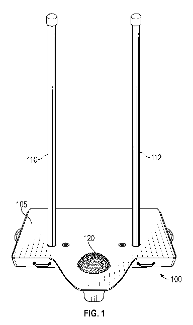
An exercise device having a top surface, the top surface having a left side and a right side, and front and back sides, where the front side includes a location for a user to rest their foot on the top surface in a central part of the top surface, and includes at least one handle location allowing a user to hold on relative to the top surface, where the handle location is attached to the top surface, and also having a bottom surface, and where the bottom surface includes a central pivot point between side to side at the central part of the top surface, said central pivot point being between first and second stability points, the first stability point being at the left side and the second stability point being at the right side, and also having a third stability point at a front portion of the bottom of the top surface, directly under the central part of the top surface where the user rests their foot, and a fourth stability point at a rear portion of the top surface, opposite to the front portion of the top surface, and a central pivot point from front to back in between the third stability point and the fourth stability point.


French Abstract

La présente invention concerne un dispositif d'exercice ayant une surface supérieure, la surface supérieure ayant un côté gauche et un côté droit, et des côtés avant et arrière, le côté avant comprenant un emplacement pour qu'un utilisateur pose son pied sur la surface supérieure dans une partie centrale de la surface supérieure, et comprenant au moins un emplacement de poignée permettant à un utilisateur de se tenir sur la surface supérieure, l'emplacement de poignée étant fixé à la surface supérieure, et ayant également une surface inférieure, et la surface inférieure comprenant un point de pivotement central entre les deux côtés au niveau de la partie centrale de la surface supérieure, ledit point de pivotement central étant situé entre des premier et deuxième points de stabilité, le premier point de stabilité étant sur le côté gauche et le deuxième point de stabilité étant sur le côté droit, et ayant également un troisième point de stabilité au niveau d'une partie avant du fond de la surface supérieure, directement sous la partie centrale de la surface supérieure où l'utilisateur pose son pied, et un quatrième point de stabilité au niveau d'une partie arrière de la surface supérieure, opposée à la partie avant de la surface supérieure, et un point de pivotement central de l'avant vers l'arrière entre le troisième point de stabilité et le quatrième point de stabilité.

Claims

Note: Claims are shown in the official language in which they were submitted.


CA 03096832 2020-10-09
WO 2019/199761 PCT/US2019/026504
What is claimed is:
1. An exercise device, comprising:
a device defining a top surface, the top surface having a left side and a
right side, and
front and back sides, where the front side includes a location for a user to
rest their
foot on the top surface in a central part of the top surface, and includes at
least one
handle location allowing a user to hold on relative to the top surface, where
the
handle location is attached to the top surface,
wherein the device also having a bottom surface, and where the bottom
surface includes a central pivot point between side to side at the central
part of the
top surface, said central pivot point being between first and second stability
points,
the first stability point being at the left side and the second stability
point being at the
right side.
2. The exercise device as in claim 1, wherein the bottom surface also includes
a
third stability point at a front portion of the bottom of the top surface,
directly under
the central part of the top surface where the user rests their foot, and a
fourth stability
point at a rear portion of the top surface, opposite to the front portion of
the top
surface, and a central pivot point from front to back in between the third
stability

CA 03096832 2020-10-09
WO 2019/199761 PCT/US2019/026504
point and the fourth stability point.
3. The exercise device as in claim 2, wherein the device includes first and
second
handles, equally spaced around the central part of the top surface where the
user's
foot is located.
4. The device as in claim 3, wherein the first and second handles extend from
the
top surface, to a point above the top surface, the first and second handles
extending
sufficiently high that the user can grasp both the first and second handles
while
standing on the central part of the top surface where the user's foot is
located.
5. The device as in claim 4, where the first and second handles are
cylindrical
poles.
6. The device as in claim 4, wherein the first and second handles are
removable
from the top surface.
7. The device as in claim 4, wherein the top surface includes plural different
holes
thereon, the plural different holes defining different locations into which
the handle
11

CA 03096832 2020-10-09
WO 2019/199761 PCT/US2019/026504
can be located.
8. The device as in claim 1, wherein the location for the user to rest their
foot on
includes an elastomeric ball, partly recessed into the top surface.
9. An exercise device, comprising:
a device defining a top surface, the top surface having a left side and a
right side, and
front and back sides, where the front side includes a location for a user to
rest their
foot on the top surface in a central part of the top surface, and includes two
handles
allowing a user to hold on relative to the top surface, attached to the top
surface,
wherein the device also having a bottom surface, and where the bottom
surface includes a central pivot point between side to side at the central
part of the
top surface, said central pivot point being between first and second stability
points,
the first stability point being at the left side and the second stability
point being at the
right side, and wherein the bottom surface also includes a third stability
point at a
front portion of the bottom of the top surface, directly under the central
part of the
top surface where the user rests their foot, and a fourth stability point at a
rear
portion of the top surface, opposite to the front portion of the top surface,
and a
12

CA 03096832 2020-10-09
WO 2019/199761 PCT/US2019/026504
central pivot point from front to back in between the third stability point
and the
fourth stability point.
10. The device as in claim 9, where the first and second handles are
cylindrical
poles.
11. The device as in claim 9, wherein the location for the user to rest their
foot on
includes an elastomeric ball, partly recessed into the top surface.
12. A method of exercising on an exercise device, comprising:
a user standing on a top surface, the top surface having a left side and a
right
side, and front and back sides, the user standing on a location on the front
side where
the user can rest their foot on the top surface in a central part of the top
surface;
the user holding two handles relative to the top surface;
the user rocking the device side to side and front to back,
where the bottom surface includes a central pivot point between side to side
at
the central part of the top surface, said central pivot point being between
first and
second stability points, the first stability point being at the left side and
the second
stability point being at the right side, and wherein the bottom surface also
includes a
13

CA 03096832 2020-10-09
WO 2019/199761 PCT/US2019/026504
third stability point at a front portion of the bottom of the top surface,
directly under
the central part of the top surface where the user rests their foot, and a
fourth stability
point at a rear portion of the top surface, opposite to the front portion of
the top
surface, and a central pivot point from front to back in between the third
stability
point and the fourth stability point.
13. The method as in claim 12, where the first and second handles are
cylindrical
poles attached relative to the top surface.
14. The method as in claim 12, wherein the location for the user to rest their
foot on
includes an elastomeric ball, partly recessed into the top surface.
14

Description

Note: Descriptions are shown in the official language in which they were submitted.


CA 03096832 2020-10-09
WO 2019/199761 PCT/US2019/026504
BALANCE BOARD
Background
[ 0 0 0 1 ] Balance of the human body is a state of function that declines
with age. As
a body ages, core muscles can weaken and become less toned, leading to less
balance.
[ 0 0 0 2 ] Exercize of the muscles needed for balance has not been adequately
addressed by any known system.
[ 0 0 0 3 ] The problem of activities for the older generation have been
ignored for
the mass population for fear and lack of programs to aid this ignored
generation.
Most gym equipment and activities, including home equipment, attempts to build
strength. However, this equipment does not cover what the inventors believe to
be
the most important decline in the body - balance.
[ 0 0 0 4 ] The inventors believe that balance is the core action with
supplementing
strength training into the physical action builds functionality for everyday
life.
1

CA 03096832 2020-10-09
WO 2019/199761 PCT/US2019/026504
Summary
[ 0005] The invention is created to help re-train the body to find its
functionality
with balance, lower and upper body strength, agility, mobility and increasing
the
quality of life in movement and ability to partake in everyday activities.
[ 0006] Embodiments describe a special balance board that enables exercise of
The solution of the embodiments solves the problem of giving back health and
movement for physical activity by addressing the body loss of balance and
confidence to maintain an active, healthy lifestyle.
2

CA 03096832 2020-10-09
WO 2019/199761 PCT/US2019/026504
Brief description of the drawings
[ 0007] The different figures show different embodiments.
[ 0008] Figure 1 shows a top view of the balance board;
[ 0009] Figure 2 illustrates the top surface of the balance board and the
holes
therein;
[0010] Figure 3 shows a rear view of the board showing how it can totter
between
sides;
[0011] Figure 4 shows the front surface; and
[0012] Figure 5 shows a person stepping on to the balance board.
3

CA 03096832 2020-10-09
WO 2019/199761 PCT/US2019/026504
Detailed description
[ 0013 ] The balance board is designed as a platform that has a center flat
pivot
point that, when stepped on, rocks side to side to a minimum degree. The
platform
has inclusive holes to attach resistance bands. The front of the platform has
a half
balance ball for specific balance training and strength for the lower body.
The
platform has two removable handles for safety and balance assist purposes. The
step
can also be stabilized with leg attachments. The design covers safety,
balance,
strength, co-ordination, lower and upper body work, all in one small self
contained
device.
[ 0014 ] An advantage of the balance board is its ability to change lives from
decline toward improvement. This training will help train to prevent and
minimize
the falls that many people suffer as they age. By training on a board that
supports all
aspects of physical needs, everyday life becomes more comfortable. The
platform
will help with walking, turning, use of stairs, carrying everyday items, and
movement for great life function. It will also build confidence to be more
active
outdoors, helping to lessen obesity gains through inactivity. The overall
health of the
user will improve and turn back the age clock of physical decline.
4

CA 03096832 2020-10-09
WO 2019/199761 PCT/US2019/026504
[ 0015] An embodiment is shown in figure 1. Figure 1 shows a front on
perspective view of the balance board assembly 100. The balance board assembly
includes a top surface 105 which includes first and second poles 110 and 112
located
into holes that are in the top surface. Figure 2 illustrates how the top
surface 110 of
the balance board is formed with a number of different holes including outer
holes
200, 202 and inner holes 205, 206. In between the inner holes 205, 206 is
located
an indentation 210 that is substantially circular, and is intended to hold an
elastomeric ball device 120, which the user's steps on in order to carry out
at least
one of the balancing exercises.
[0016] Figure 1 also shows the poles 110, 112 respectively located in the
outer
holes 200, 202. The poles can be moved into the inner holes 205, 206 for
different
exercises.
[0017] The base has a number of bottom curvature points explained herein and
shown throughout the drawings, which enable the base to be rocked from side to
side
and front to back while maintaining over all stability and without being
tipped over.
Figure 3 illustrates the base 100, and illustrates how the bottom surface of
the base
300 is uneven, having a substantially seesaw shape, with the first side 305
thinner at
its first end 306 and linearly increasing in thickness from the first end 306
to the
center portion 310, which is the portion where there is the thickest distance
between

CA 03096832 2020-10-09
WO 2019/199761 PCT/US2019/026504
the top platform of the base 320, and the bottom surface of the base 300. At
this
thickest portion 310, the base begins again linearly thinning until reaching
the
second end 315 which is a second end of minimum thickness opposite to the
first
end. In this way, the bottom of the base is not stable and flat on the floor,
but rather
is only stable in its two side to side positions including resting on the
first end, where
the base is resting on a flat surface 307 formed between the first and 306 and
the
middle portion 310, or when it is resting on the second flat surface 314
formed
between the middle portion and the second end 315.
[ 0018] In an alternative embodiment, the surface 307 is not actually flat,
but is
somewhat curved.
[0019] Figure 4 illustrates a face on view of the base, showing how the bottom
surface of the base has two different sections. The rear section 400 includes
the
sizing parameters shown in figure 3, where the rear section 400 has a
thickness that
linearly gets thicker towards the center portion, and linearly gets thinner
towards the
edge portions, forming an unstable base. The front portion 410, however,
extends
from the rear portion 400, and includes a rounded bottom portion 412 directly
under
the location of the elastomeric ball on which the user steps to carry out the
exercises.
[0020] Figure 5 illustrates a side view of the base showing the unstable
portions
from front to back. The base is thinnest at its central portions 50 hundred
and 501.
6

CA 03096832 2020-10-09
WO 2019/199761 PCT/US2019/026504
From portion 500 to the first and 520, the base gradually reduces in
thickness.
Section 500 is actually the bottom portion of the front portion 410. Figure 5
illustrates an embodiment where there is only structure at certain points such
as 510,
and other section such as 520 are hollow. Similarly, the center portion 500,
501
includes 2 structural points, and a hollow section in between them. The
section
from 501 to the low point at the other end at 510 is similarly a curved
section
allowing for teetering back and forth, but maintaining stability at either
alternate
and.
[ 0021 ] Figure 6 illustrates the operation, where the user stands at the ball
and of
the device, holds onto the handles 110, 112, and stands on the ball 600. While
stepping on the elastomeric ball, the user forces the exercise board from one
side to
the other, thus exercising their core muscles.
[ 0022 ] The structure of the invention is based off the center flat stability
point of
the base 100. The curvature off of the base that allows for the platform to be
rocked
from side to side without danger of tipping over. The front of the design
creates a
stability ball insert all in one setup. The poles inserted into the platform
as unique as
a removable stability assist. These can also be used for the physical training
segment
of the program.
7

CA 03096832 2020-10-09
WO 2019/199761 PCT/US2019/026504
[0023] The platform, as a rocker, can be used for upper body strength training
due
to the need of dynamic muscle contraction to prevent the rocking. The platform
is
also perfect for abdominal work as shifting of the body weight can change the
intensity of the core work from decline to incline training. The built in
holes allow
for added resistance training with multiple attachments. Additional legs that
insert
into the base allow for the rocker to be transformed into a solid non-rocking
base for
additional training programs.
[0024] The balance board addresses all aspects of training through this one
single
device. The device allow low impact core exercizes by rocking, solid, height
adjustment and multi-entry points of use for the user while providing
stability poles
to help the user. Removing the poles also creates a larger base platform for
additional activities and body function exercises, and makes it easy to store.
[0025]
The previous description of the disclosed exemplary embodiments is provided
to enable any person skilled in the art to make or use the present invention.
Various
modifications to these exemplary embodiments will be readily apparent to those
skilled in the art, and the generic principles defined herein may be applied
to other
embodiments without departing from the spirit or scope of the invention. Thus,
the
present invention is not intended to be limited to the embodiments shown
herein but
8

CA 03096832 2020-10-09
WO 2019/199761 PCT/US2019/026504
is to be accorded the widest scope consistent with the principles and novel
features
disclosed herein.
9

Representative Drawing
A single figure which represents the drawing illustrating the invention.
Administrative Status

2024-08-01:As part of the Next Generation Patents (NGP) transition, the Canadian Patents Database (CPD) now contains a more detailed Event History, which replicates the Event Log of our new back-office solution.

Please note that "Inactive:" events refers to events no longer in use in our new back-office solution.

For a clearer understanding of the status of the application/patent presented on this page, the site Disclaimer , as well as the definitions for Patent , Event History , Maintenance Fee  and Payment History  should be consulted.

Event History

Description Date
Compliance Requirements Determined Met 2024-05-21
Letter Sent 2024-04-09
Maintenance Fee Payment Determined Compliant 2022-04-29
Inactive: Cover page published 2020-11-23
Letter sent 2020-11-02
Letter sent 2020-10-30
Inactive: IPC assigned 2020-10-26
Priority Claim Requirements Determined Compliant 2020-10-26
Request for Priority Received 2020-10-26
Inactive: First IPC assigned 2020-10-26
Application Received - PCT 2020-10-26
National Entry Requirements Determined Compliant 2020-10-09
Application Published (Open to Public Inspection) 2019-10-17

Abandonment History

There is no abandonment history.

Maintenance Fee

The last payment was received on 2023-04-06

Note : If the full payment has not been received on or before the date indicated, a further fee may be required which may be one of the following

  • the reinstatement fee;
  • the late payment fee; or
  • additional fee to reverse deemed expiry.

Patent fees are adjusted on the 1st of January every year. The amounts above are the current amounts if received by December 31 of the current year.
Please refer to the CIPO Patent Fees web page to see all current fee amounts.

Fee History

Fee Type Anniversary Year Due Date Paid Date
Basic national fee - standard 2020-10-09 2020-10-09
MF (application, 2nd anniv.) - standard 02 2021-04-09 2021-04-06
Late fee (ss. 27.1(2) of the Act) 2024-10-09 2022-04-29
MF (application, 3rd anniv.) - standard 03 2022-04-11 2022-04-29
MF (application, 4th anniv.) - standard 04 2023-04-11 2023-04-06
Owners on Record

Note: Records showing the ownership history in alphabetical order.

Current Owners on Record
DANIEL BENJAMIN METCALFE
ROBERT LELAND EUBANKS
Past Owners on Record
None
Past Owners that do not appear in the "Owners on Record" listing will appear in other documentation within the application.
Documents

To view selected files, please enter reCAPTCHA code :


To view images, click a link in the Document Description column. To download the documents, select one or more checkboxes in the first column and then click the "Download Selected in PDF format (Zip Archive)" or the "Download Selected as Single PDF" button.

List of published and non-published patent-specific documents on the CPD .

If you have any difficulty accessing content, you can call the Client Service Centre at 1-866-997-1936 or send them an e-mail at CIPO Client Service Centre.


Document
Description 
Date
(yyyy-mm-dd) 
Number of pages   Size of Image (KB) 
Claims 2020-10-08 5 135
Abstract 2020-10-08 1 66
Representative drawing 2020-10-08 1 25
Description 2020-10-08 9 239
Drawings 2020-10-08 4 115
Commissioner's Notice: Request for Examination Not Made 2024-05-20 1 519
Commissioner's Notice - Maintenance Fee for a Patent Application Not Paid 2024-05-20 1 566
Courtesy - Letter Acknowledging PCT National Phase Entry 2020-10-29 1 586
Courtesy - Letter Acknowledging PCT National Phase Entry 2020-11-01 1 586
Courtesy - Acknowledgement of Payment of Maintenance Fee and Late Fee 2022-04-28 1 421
National entry request 2020-10-08 7 214
International search report 2020-10-08 1 51
Patent cooperation treaty (PCT) 2020-10-08 2 78
Patent cooperation treaty (PCT) 2020-10-08 3 114