Note: Descriptions are shown in the official language in which they were submitted.
CA 03097180 2020-09-15
EASY-TO-CONTROL INTERVENTIONAL INSTRUMENT DELIVERY
DEVICE
.. TECHNICAL FIELD
[0001] The present disclosure relates to the technical field of medical
apparatuses,
and in particular, to a delivery device for implanting an artificial heart
valve into the heart.
BACKGROUND
[0002] Heart valve disease is one of the most common heart diseases in China,
and
the main symptom is valve damage caused by rheumatic fever. In recent years,
with the
development of the aging population, valve degeneration such as calcification
and
mucus degeneration, etc., and valve damage with metabolic disorder are also
increasing
in China. In addition, congenital valvular disease is also one of the common
reasons for
the heart disease. A considerable number of high-risk patients with heart
valve disease,
such as patients with severe valve insufficiency, elderly patients who are not
suitable for
surgical valve replacement, or patients with advanced tumors and valve
insufficiency,
require new and less invasive interventional treatment. Implantable heart
valves were
developed under the inspiration of surgical heart valve replacement. In recent
years,
percutaneous valve interventions have emerged and have been successfully
applied to
humans since 2000. From the stage of experimental research to the stage of
small-scale
clinical research, valve intervention breaks through the technical
"bottleneck" and can
be widely and quickly applied to the clinical practices, and becomes the focus
of
interventional cardiology again.
[0003] In the prior art, an artificial heart valve stent is compressed and
delivered into
the human body through a delivery device. The compressed valve stent is
usually flexible,
and when in a compressed configuration, it applies a great force to the
compressing
catheter. Due to the great force, it is difficult to gradually and precisely
release the valve
stent, resulting in excessive friction between the valve stent and the inner
wall of the
.. blood vessel.
[0004] CN patent No. 101953725 discloses an artificial heart valve stent,
which
includes an aortic stent, a valve stent, an outflow channel stent, and a
connecting ear.
When the heart valve is compressed into the delivery device, the connecting
ear can be
1
Date Recue/Date Received 2020-09-15
CA 03097180 2020-09-15
engaged in a fixing component of the delivery device for the stent. During the
release of
the valve stent, the valve stent is gradually released through the engagement
of the
connecting ear and the constraint of the outer sheath. However, in the prior
art, the
constraint force of the connecting ear of the valve stent is small, and the
connecting ear
can easily spring out of the fixing component of the delivery device for the
stent at the
end of the release of the valve stent, which causes the valve stent to be
completely
released. At this time, if problems such as positioning deviation occur, the
valve stent
cannot be retracted in time and can only be replaced by surgery.
[0005] In order to overcome the above-mentioned problems during the release of
the
valve stent in the human body, US Patent No. 5,683,451 discloses a delivery
device and
a method for controlling the release of a tubular prosthesis. The friction to
the delivery
catheter caused by a flexible expansion during delivery and release of the
prosthesis is
reduced by providing a rail in the delivery device. This invention reduces the
friction
between the prosthesis and the delivery catheter. However, the problem that
the valve
stent is suddenly and completely released due to an excessive expansion force
during
the release is not solved. The valve stent after being released into position
cannot be
adjusted or repositioned, which not only requires high control accuracy for
surgery, but
also contains certain risks.
SUMMARY
[0006] The present disclosure provides a delivery device for controlling the
release of
an implantable instrument, which can fix the end of the implantable instrument
during the
release of the implantable instrument, prevent the implantable instrument from
getting
out of control and falling off a fixing head during the release due to a great
expansion
force, and achieve repositioning and retrieval of the implantable instrument
during the
release.
[0007] A delivery device facilitating control of an implantable instrument
comprising:
a core tube having a distal end and a proximal end,
a guiding head which is fixed at the distal end of the core tube,
a fixing head which is fixed on the core tube and is provided with at least
one
positioning portion on an outer wall thereof for engaging with at least one
connecting ear
of the implantable instrument, wherein the proximal end of the core tube
extends through
and out of the fixing head, with a mounting portion for the implantable
instrument formed
2
Date Recue/Date Received 2020-09-15
CA 03097180 2020-09-15
between the guiding head and the fixing head,
an outer sheath which is configured for surrounding an outer periphery of the
mounting portion for the implantable instrument and is slidable in an axial
direction, and
at least one movable limiting bar having a proximal end being a starting end
which
is fixed with the core tube or the fixing head, and a distal end being a
terminal end which
is configured between the mounting portion for the implantable instrument and
the outer
sheath and is movable, wherein,
the at least one movable limiting bar is configured to maintain the engagement
between the at least one connecting ear and the at least one positioning
portion under
.. the constraint of the outer sheath when the implantable instrument is in a
loaded
configuration.
[0008] In the present disclosure, the movable limiting bar is located between
the outer
sheath and the implantable instrument so that the inner wall of the outer
sheath can
radially constrain the implantable instrument and prevent the implantable
instrument
from getting out of control and falling off unexpectedly. Furthermore, the
movable limiting
bar can reduce the contact area between the outer sheath and the implantable
instrument to a certain extent and reduce the friction therebetween, so that
less force
from an operator is required during pushing and withdrawing of the outer
sheath so that
the release and the retraction of the implantable instrument can be precisely
controlled.
.. [0009] The mounting portion for the implantable instrument can be
interpreted as a
position where the implantable instrument is located when loaded. The main
portion of
the implantable instrument is located between the distal end of the fixing
head and the
proximal end of the guiding head. In general, for easy positioning, the
implantable
instrument is partially overlapped on the outer walls of the fixing head and
the guiding
head. Therefore, the position where the implantable instrument is located when
loaded
can be considered as an axial position between the distal end of the fixing
head and the
proximal end of the guiding head.
[0010] The movable limiting bar, without constraint of the outer sheath, can
freely
swing, or retain position and shape relative to the implantable instrument or
the core tube
only by utilizing the material strength thereof. The term of "movable" means
that one end
of the movable limiting bar is fixed, and the other end can swing at least in
the radial
direction without external constraint. Due to the material strength thereof,
the movable
3
Date Recue/Date Received 2020-09-15
CA 03097180 2020-09-15
limiting bar may displace in the circumferential direction.
[0011] The loaded configuration of the implantable instrument includes an
unreleased
configuration, in which the implantable instrument is completely surrounded by
the outer
sheath, and a partial released configuration, in which the implantable
instrument is
partially exposed out of the outer sheath. In the loaded configuration, the
movable limiting
bar maintains the engagement between the connecting ear of the implantable
instrument
and the positioning portion under the constraint of the outer sheath to
prevent the
connecting ear from falling off the fixing head.
[0012] The implantable instrument has a released configuration, in which the
implantable instrument is completely exposed out of the outer sheath. In the
released
configuration, the force from the movable limiting bar to maintain the
engagement
between the connecting ear and the positioning portion is released so that the
connecting
ear of the implantable instrument is allowed to fall off the positioning
portion.
[0013] In other words, the movable limiting bar maintains the engagement
between
the connecting ear of the implantable instrument and the positioning portion
only in the
loaded configuration.
[0014] The engagement structure of the implantable instrument with the
positioning
portion is generally configured as a connecting portion of the implantable
instrument, and
the connecting ear of the implantable instrument is at least a part of the
connecting
portion.
[0015] The positioning portion has an opening area, through which the radial
position
of the connecting ear can be changed. In the loaded configuration, the movable
limiting
bar blocks the opening area, and can completely or partially close the opening
area.
[0016] The positioning portion has a radial opening area. During the release
of the
.. implantable instrument, the connecting ear falls off the positioning
portion through the
opening area. In the loaded configuration, the movable limiting bar blocks the
opening
area and prevents the connecting ear from falling off. In the unreleased
configuration,
the movable limiting bar completely or partially closes the opening area at
the opening
of the opening area on the outer periphery of the fixing head.
4
Date Recue/Date Received 2020-09-15
CA 03097180 2020-09-15
[0017] After the implantable instrument is loaded into the outer sheath, the
movable
limiting bar maintains the engagement between the connecting ear and the
positioning
portion under the constraint of the outer sheath. During the release of the
connecting ear
by withdrawing the outer sheath, the movable limiting bar is gradually
released out of the
outer sheath and it cannot freely swing until the connecting ear is completely
released
and falls off the fixing head. The released movable limiting bar would no
longer apply
radial pressing force to the connecting ear, and also would not constrain the
connecting
ear.
[0018] After the implantable instrument is loaded into the outer sheath, the
movable
limiting bar also serves as a spacer compensating the tolerance between the
outer
sheath and the connecting ear and filling the radial gap between the outer
sheath and
the connecting ear. The movable limiting bar has a simple structure and would
not
increase the radial size of the delivery device when implanted, and can
enhance the
engagement between the known implantable instrument and the fixing head to
improve
the connection therebetween. The radial force from the movable limiting bar to
the
connecting ear will be released with the withdrawal of the outer sheath so
that the
movable limiting bar would not obstruct the released valve stent.
[0019] The starting end of the movable limiting bar is fixed with at least one
of the core
tube and the fixing head.
[0020] The position of the fixing head relative to the core tube is fixed. The
starting
end of the movable limiting bar is fixed with at least one of the core tube
and the fixing
head. Alternatively, at least the axial position of the starting end of the
movable limiting
bar is fixed relative to at least one of the core tube and the fixing head.
[0021] The proximal end of the movable limiting bar is fixed using at least
one of the
following techniques:
a) the starting end of the movable limiting bar is fixed on the fixing head;
b) the starting end of the movable limiting bar is fixed on the core tube and
located at the
proximal end of the fixing head.
[0022] The proximal end of the movable limiting bar is fixed with the core
tube or the
5
Date Recue/Date Received 2020-09-15
CA 03097180 2020-09-15
fixing head, and the distal end of the movable limiting bar is movable
relative to the core
tube or the fixing head. For example, the starting end of the movable limiting
bar is fixed,
adjacent to the fixing head, or at the rear of the fixing head at the proximal
end (the end
adjacent to an operator in the direction of the delivery device), or at the
core tube
connected with the rear. Before operation, the outer sheath constrains the
implantable
instrument and the movable limiting bar and causes the movable limiting bar to
radially
and inwardly abut against the outer periphery of the implantable instrument.
The movable
limiting bar abutting against the outer periphery of the implantable
instrument can be
interpreted as the movable limiting bar only contacting with the outer
periphery of the
implantable instrument. In other words, the movable limiting bar does not
extend into the
radial inner side of the implantable instrument. During the release of the
implantable
instrument which has already been in the human body, the movable limiting bar
turns
outwardly with the withdrawal of the outer sheath and the release of the
implantable
instrument.
[0023] Without constraint of the outer sheath, the movable limiting bar
changes its
radial position by deforming partially or completely to allow the connecting
ear to move
radially and outwardly to fall off the positioning portion. At least a part of
the movable
limiting bar has a deformable structure that is made of flexible material
and/or is formed
as an articulated mechanism.
[0024] Preferably, the positioning portion is configured as a positioning
protrusion, and
when the implantable instrument assumes the loaded configuration, the
connecting ear
is configured to surround a respective positioning protrusion, and the movable
limiting
bar is configured to overlap and abut against an outer side of a respective
connecting
ear to maintain the engagement between the connecting ear and the positioning
portion.
[0025] Preferably, the positioning portion is configured as a positioning
groove, and
when the implantable instrument assumes the loaded configuration, the
connecting ear
is configured to be inserted in a respective positioning groove, and the
movable limiting
bar is configured to overlap and abut against an outer side of a respective
connecting
ear to maintain the engagement between the connecting ear and the positioning
portion.
[0026] In order to control the axial position of the implantable instrument,
the proximal
end of the implantable instrument is generally provided with a connecting ear
for
6
Date Recue/Date Received 2020-09-15
CA 03097180 2020-09-15
engaging with the fixing head. The connecting ear is generally T-shaped, L-
shaped, ring-
shaped, U-shaped, or V-shaped. The positioning portion may be a positioning
groove for
receiving the T-shaped or the L-shaped connecting ear, or may be a protrusion
surrounded by the ring-shaped, the U-shaped, or the V-shaped connecting ear,
for
limiting the axial position of the implantable instrument in the loaded
configuration. The
shape of the connecting ear itself in the present disclosure may be known in
the prior art,
and is not the focus of the improvement for the present disclosure.
[0027] The portion of the movable limiting bar received in the positioning
groove
radially and inwardly contacts with or abuts against the connecting ear.
[0028] The positioning portion may be configured as a positioning protrusion
or a
positioning groove. In the loaded configuration, the connecting ear is
surrounded around
the respective positioning protrusion or inserted in the respective
positioning groove.
[0029] In the loaded configuration, the movable limiting bar can maintain the
engagement between the connecting ear and the positioning portion by directly
overlapping and abutting against the connecting ear or blocking the
positioning portion
at the opening area.
[0030] The movable limiting bar overlapping and abutting against the
connecting ear
also means the movable limiting bar blocking the opening area, in which case,
due to
the limited radial gap, the movable limiting bar contacts with and presses
against the
connecting ear. In the case where the radial gap between the outer sheath and
the
positioning portion is larger, the movable limiting bar may not directly
radially contact with
the connecting ear, but locks the connecting ear by blocking the opening area.
After the
radial gap is filled by the movable limiting bar, the depth of the remaining
gap should be
less than the thickness of the connecting ear to prevent the connecting ear
from falling
off the positioning portion. In the loaded configuration, the radial outer
side of the
movable limiting bar abuts against the inner wall of the outer sheath, and the
radial inner
side of the movable limiting bar abuts against the connecting ear. Further,
the movable
limiting bar contacts with the implantable instrument at the radial outer side
of the
implantable instrument.
[0031] In the loaded configuration, the movable limiting bar is aligned with
the outer
wall of the fixing head in the radial direction, or protrudes from the outer
wall of the fixing
7
Date Recue/Date Received 2020-09-15
CA 03097180 2020-09-15
head in the radial direction.
[0032] In the loaded configuration, the movable limiting bar, under the
constraint of the
outer sheath, at least has a radial component to prevent the connecting ear of
the
implantable instrument from moving radially and outwardly, and to urge the
connecting
portion of the implantable instrument to abut against the fixing head.
[0033] The positioning protrusion or the positioning groove is the position of
the
positioning portion engaged with the connecting ear, which serves as a
constraint
structure for constraining the axial movement of the connecting ear in the
loaded
configuration, and allows the implantable instrument to move relative to the
positioning
portion in the released configuration to release the axial constraint.
[0034] In the loaded configuration, the portion of the movable limiting bar
engaged
with the positioning groove is radially received in the positioning groove in
a partial or
complete manner.
[0035] For example, in the case where a positioning groove is adopted, the
connecting
ear is latched in the positioning groove in the loaded configuration so as to
achieve an
axial positioning. After the outer sheath is withdrawn, the connecting ear
falls off the
positioning groove outwardly in the radial direction of the stent.
[0036] The positioning groove can be combined with a protrusion which may be
provided at the bottom of the positioning groove and engages with the
connecting ear in
a form-fit manner to enhance the positioning.
[0037] In the case where the connecting ear has a U-shaped or an annular
structure,
one side of the U-shaped or the annular structure is connected with the
implantable
instrument. The positioning portion of the fixing head is configured as a
positioning
protrusion which engages with the U-shaped or the annular structure. The U-
shaped or
the annular structure can be extended around the positioning protrusion to
achieve an
axial positioning. In order to prevent the connecting ear from radially
protruding too much,
a recess is preferably provided around the outer periphery of the positioning
protrusion,
i.e., on the outer wall of the fixing head. The connecting ear is received in
the recess,
and the outer surface thereof is aligned with the outer wall of the fixing
head in the radial
direction.
8
Date Recue/Date Received 2020-09-15
CA 03097180 2020-09-15
[0038] Preferably, the number of the movable limiting bars is the same as that
of the
positioning grooves, and the movable limiting bars correspond to the
positioning grooves
respectively in a circumferential direction.
[0039] The positioning groove prevents the movable limiting bar from
displacing during
the retraction and release.
[0040] In the loaded configuration, the proximal end of the movable limiting
bar under
the constraint of the outer sheath is tightly latched in the positioning
groove and presses
against the connecting ear received in the positioning groove. During the
release of the
implantable instrument by withdrawing the outer sheath, the implantable
instrument is
prevented from getting out of control and falling off under the pressing and
fixing of the
movable limiting bar in the positioning groove. If the implantable instrument
is released
at an undesired position during release, the released implantable instrument
can be
compressed and retracted by pushing the outer sheath. At this time, the
connecting ear
is tightly surrounded by the movable limiting bar and the outer sheath,
thereby ensuring
a safe control for the implantable instrument and the repositioning.
[0041] Preferably, the terminal end of the movable limiting bar at least
extends to the
position corresponding to the connecting ear. In other words, the terminal end
of the
movable limiting bar at least extends to cover a part of the connecting ear to
limit the
radial movement of the connecting ear. The terminal end of the movable
limiting bar may
further extend towards the distal end and slidably engages with the outer
sheath in the
axial direction.
[0042] Preferably, the movable limiting bar is configured as a single strip,
or a
branched structure, wherein branches of the branched structure extend towards
the
distal end to overlap and abut against an outer side of the connecting ear,
and a
connection of the branched structure connecting the branches is fixed at an
outer side
of the fixing head.
[0043] The terminal end of the movable limiting bar is relative to the
starting end and
can also be interpreted as the distal end of the movable limiting bar.
[0044] Preferably, the most distal end of the movable limiting bar is aligned
with the
most distal end of the fixing head, or extends no more than the most distal
end of the
9
Date Recue/Date Received 2020-09-15
CA 03097180 2020-09-15
fixing head, or extends slightly beyond the most distal end of the fixing
head.
[0045] In the case where the movable limiting bar has a minimum length, it
should at
least extend to cover the connecting ear. In order to further improve the
pressing
performance, the terminal end of the movable limiting bar may further extend
to the distal
end of the fixing head, or slightly beyond the distal end of the fixing head,
such as by no
more than lcm.
[0046] The distal end of the movable limiting bar extends to the portion of
the
implantable instrument having the greatest diameter. After a certain
implantable
instrument is released, the diameters of different portions of the implantable
instrument
.. may be different. In this case, the distal end of the movable limiting bar
extends to the
portion of the implantable instrument having the greatest diameter.
[0047] In the case where the movable limiting bar has a maximum length, the
entire
movable limiting bar should be able to be retracted in the outer sheath, and
the terminal
end of the movable limiting bar is aligned with the distal end of the
implantable instrument
in the outer sheath. In this case, the movable limiting bar is long enough to
cover the
overall implantable instrument. The movable limiting bar serves as a slide
rail so that the
outer sheath can be pushed and withdrawn without direct contacting with the
implantable
instrument.
[0048] In the loaded configuration of the implantable instrument, the movable
limiting
bar constrains the connecting ear in the positioning groove under the
constraint of the
outer sheath. The inner wall of the outer sheath contacts with the movable
limiting bar
and provides radial constraint. The movable limiting bar blocks the connecting
ear in the
positioning groove and prevents it from falling off.
[0049] Preferably, the positioning groove axially extends through the fixing
head, and
a portion of the movable limiting bar for engaging with the positioning groove
is
configured to be partially or completely received in the positioning groove.
[0050] The movable limiting bar extends through the positioning groove to the
distal
end. The positioning groove not only axially extends through the fixing head,
but also is
opened at the radial outer side thereof. In other words, the positioning
groove has a
radial opening. The movable limiting bar is not strictly required to be
completely located
Date Recue/Date Received 2020-09-15
CA 03097180 2020-09-15
at the inner side of the radial opening. A part of the movable limiting bar
can be located
at the outer side of the radial opening. For example, the movable limiting bar
may have
a T-shaped cross section. The bottom of the T-shaped structure may be located
in the
positioning groove to block the connecting ear, and the top of the T-shaped
structure
may be located at the outer side of the radial opening with a limited size in
such a manner
that the movable limiting bar can simultaneously engage with the inner side of
the outer
sheath and the connecting ear.
[0051] Preferably, an area of the positioning groove that axially extends
through the
fixing head is configured to be closed by the movable limiting bar.
[0052] In order to prevent the connecting ear from falling off, the width of
the movable
limiting ear may be equal to or slightly greater than the width of the radial
opening of the
area that axially extends through the fixing head so as to completely close
the radial
opening. Even if the width of the movable limiting ear may be smaller than the
width of
the radial opening, the gap formed therebetween should not be too large to
allow the
connecting ear to fall off. Preferably, the width of the movable limiting ear
is equal to the
width of the radial opening, which can further prevent the movable limiting
ear from
displacing.
[0053] Preferably, a portion of the movable limiting bar that is configured to
be received
in the positioning groove radially and inwardly contacts with or abuts against
the
connecting ear.
[0054] Even though the movable limiting bar can block the connecting ear,
there may
be a different relationship between the total thickness (a radial dimension)
of the movable
limiting bar and the connecting ear and the depth of the positioning groove.
When the
outer sheath covers and contacts with the outer periphery of the fixing head,
the movable
limiting bar overlaps the outer wall of the connecting ear. In the case where
the total
thickness of the movable limiting bar and the connecting ear is greater than
the depth of
the positioning groove, the movable limiting bar radially and inwardly abuts
against the
connecting ear. Conversely, the movable limiting bar only contacts with the
connecting
ear without a strong constraint force to the connecting ear. In any event, the
movable
limiting bar can constrain the connecting ear. Further preferably, the movable
limiting bar
abuts against the connecting ear so that the movable limiting bar can still
constrain the
11
Date Recue/Date Received 2020-09-15
CA 03097180 2020-09-15
connecting ear even if the axial force to the outer sheath is too large or the
outer sheath
is deformed.
[0055] Preferably, the movable limiting bar is configured to be aligned with
or protrude
from the outer wall of the fixing head in a radial direction.
[0056] The movable limiting bar at least extends radially and outwardly to the
outer
wall of the fixing head so that an undesired gap between the movable limiting
bar and
the inner wall of the outer sheath is avoided. The inner wall of the outer
sheath abuts
against the movable limiting bar and presses the connecting ear in the
positioning portion
of the fixing head.
[0057] Optionally, a portion of the movable limiting bar for engaging with the
connecting ear extends in a straight line or a curved line.
[0058] In the case where the two sides of the movable limiting bar abut
against the
corresponding sides of the positioning groove, the movable limiting bar
extending in the
curved line can be appropriately narrowed so that it will be easy to turn
outwardly to
release the connecting ear during the release of the implantable instrument,
thereby
preventing the connecting ear from falling off with delay.
[0059] Optionally, the portion of the movable limiting bar for engaging with
the
connecting ear extends uniformly or non-uniformly in width.
[0060] The movable limiting bar has at least a portion that is overlapped with
the
positioning portion in the circumferential direction.
[0061] Optionally, the portion of the movable limiting bar for engaging with
the
connecting ear extends uniformly or non-uniformly in thickness. In the event
that the
portion of the movable limiting bar that engages with the connecting ear
extends in a
straight line or a curved line, it can be configured to extend uniformly or
non-uniformly in
width and/or in depth. The local strength of the movable limiting bar can be
adjusted by
changing the width or thickness so as to simultaneously ensure the constraint
on the
connecting ear and the release of the connecting ear.
[0062] Preferably, the terminal end of the movable limiting bar has a smooth
outer
12
Date Recue/Date Received 2020-09-15
CA 03097180 2020-09-15
periphery.
[0063] During operation, the movable limiting bar radially expands with the
release of
the implantable instrument. In order to prevent the terminal end of the
expanding
movable limiting bar from piercing the inner wall of the blood vessel, the
terminal end of
the movable limiting bar has a smooth outer profile, such as in the form of an
approximate
spherical crown or a chamfered edge.
[0064] Preferably, the movable limiting bars comprise two, three, or four
movable
limiting bars that are evenly arranged in a circumferential direction.
[0065] Preferably, the movable limiting bars have the same or different
lengths.
[0066] In the case where the movable limiting bars have different lengths, the
terminal
ends of the movable limiting bars may be located at different positions. For
example, at
least one of the movable limiting bars extends to be aligned with the distal
end of the
fixing head, and at least one of the movable limiting bars extends to the
distal end of the
mounting portion for the implantable instrument.
[0067] There is a plurality of movable limiting bars which simultaneously or
successively transform into the loaded configurations.
[0068] Preferably, there is a plurality of movable limiting bars which
simultaneously or
successively transform from the loaded configurations into the released
configurations.
[0069] The loaded configuration can be interpreted as the movable limiting
bars are
completely surrounded by the outer sheath, and the released configuration can
be
interpreted as the movable limiting bars are completely exposed out of the
outer sheath.
In the case where the distal ends of the movable limiting bars are located at
different
axial positions, the movable limiting bars successively transform into the
loaded
configurations. In the case where the distal ends of the movable limiting bars
are located
at the same axial position, the movable limiting bars simultaneously transform
into the
loaded configurations, which also means that the movable limiting bars
simultaneously
transform from the loaded configurations into the released configurations.
[0070] Preferably, there are three movable limiting bars with the same length
which
13
Date Recue/Date Received 2020-09-15
CA 03097180 2020-09-15
are configured as long strips.
[0071] Preferably, the movable limiting bar has a hollow or a solid structure.
[0072] Preferably, the movable limiting bar is configured as a flat strip with
a solid
structure.
[0073] The movable limiting bar configured as a flat strip occupies a small
space in
the radial direction of the mounting portion for the implantable instrument,
which
functions to reduce the outer diameter of the compressed delivery device.
[0074] Preferably, the movable limiting bar has a length of 10 mm to 80 mm, a
width
of 1 mm to 2 mm, and a thickness of 0.2 mm to 0.5 mm.
.. [0075] Preferably, the movable limiting bar is fixed with a connected part
such as the
core tube or the fixing head in a bonding, tying, latching, welding, or one-
piece manner.
[0076] The movable limiting bar comprises a starting end at one end thereof,
an
extending section at the middle portion thereof, and a terminal end at the
other end
thereof. The starting end of the movable limiting bar is located, at the rear
of the fixing
.. head at the proximal end thereof, or at a portion of the core tube that
connects the rear
of the fixing head and an inner sheath. The starting end of the movable
limiting bar is
fixed with the connected part in a bonding, tying, latching, welding, or one-
piece manner.
The movable limiting bar extends from the starting end to the distal end. In a
released
configuration, the starting end of the movable limiting bar is fixed, and the
extending
section and the terminal end expand in the axial direction of the core tube.
[0077] Preferably, at least one of a portion of the movable limiting bar for
engaging
with the sheath and a portion of the movable limiting bar for engaging with
the
implantable instrument has a smooth surface and/or a lubricious coating.
[0078] Preferably, the movable limiting bar is made of PTFE material.
[0079] Preferably, the delivery device further comprises at least one fixing
and guiding
bar that is provided at an inner wall of the sheath and extends in the axial
direction.
[0080] One side of the fixing and guiding bar is fixed in the tubular housing
of the outer
14
Date Recue/Date Received 2020-09-15
CA 03097180 2020-09-15
sheath at the distal end (in the direction of the delivery device away from an
operator).
The fixing and guiding bar extends in the axial direction of the tubular
housing. When the
implantable instrument is retracted and released by the outer sheath, the
implantable
instrument directly contacts with the fixing and guiding bar located in the
tubular housing
of the outer sheath, and it can be controlled quickly and precisely through
the smooth
rail provided by the fixing and guiding bar.
[0081] The fixing and guiding bar can be fixed to the inner wall of the outer
sheath only
at the contact portion therebetween, or at a plurality of fixing points spaced
from each
other, or be entirely fixed to the inner wall of the outer sheath. Since the
fixing and guiding
bar is required to move back and forth with the outer sheath, preferably at
least the two
axial ends of the fixing and guiding bar are fixed with the inner wall of the
outer sheath
to avoid a space interference caused by the evagination of the fixing and
guiding bar.
[0082] Before operation, the outer sheath constrains the implantable
instrument, and
the fixing and guiding head abuts against the implantable instrument. During
the
subsequent release of the implantable instrument, the side of the fixing and
guiding bar
adjacent to the implantable instrument provides a smooth rail between the
tubular
housing of the outer sheath and the implantable instrument, which reduces the
friction
therebetween and facilitates the control and the release of the implantable
instrument.
[0083] Preferably, the movable limiting bars and the fixing and guiding bars
are
arranged alternatively in a circumferential direction.
[0084] The positioning grooves of the fixing head and the fixing and guiding
bars are
arranged alternatively, which also means that the movable limiting bars and
the fixing
and guiding bars are arranged alternatively.
[0085] Preferably, the terminal end of the movable limiting bar and a distal
end of the
fixing and guiding bar are aligned with or offset from each other in an axial
direction.
[0086] Preferably, there are two, three, or four fixing and guiding bars that
are evenly
arranged in a circumferential direction.
[0087] Preferably, the fixing and guiding bars have the same or different
lengths.
Date Recue/Date Received 2020-09-15
CA 03097180 2020-09-15
[0088] Preferably, there are three fixing and guiding bars with the same
length which
are configured as long strips.
[0089] Preferably, the fixing and guiding bar has a hollow or a solid
structure.
[0090] Preferably, the fixing and guiding bar is configured as a flat strip
with a solid
structure.
[0091] The fixing and guiding bar configured as a flat strip occupies a small
space in
the radial direction of the mounting portion for the implantable instrument,
which
functions to reduce the outer diameter of the compressed delivery device.
[0092] Preferably, the fixing and guiding bar has a length of 10 mm to 80 mm,
a width
of 1 mm to 2 mm, and a thickness of 0.2 mm to 0.5 mm.
[0093] Preferably, the fixing and guiding bar has a length of 60 mm to 80 mm.
[0094] The shape and size of the movable limiting bar and the fixing and
guiding bar
are independently provided. For example, they can be configured as long strips
with solid
or hollow structures. Preferably, the cross sections of the movable limiting
bar and the
fixing and guiding bar are flat. In order to reduce the radial size of the
entire distal end of
the outer sheath, the thickness direction of the flat structure corresponds to
the radial
direction of the outer sheath.
[0095] In order to control the release and the retraction of the stent well,
the movable
limiting bar and the fixing and guiding bar are configured with appropriate
sizes to reduce
the contact area between the stent and the outer sheath, thereby reducing the
friction
therebetween.
[0096] Preferably, the fixing and guiding bar is fixed with the inner wall of
the sheath
in a bonding, tying, latching, welding, or one-piece manner.
[0097] Preferably, a portion of the fixing and guiding bar for engaging with
the
implantable instrument has a smooth surface and/or a lubricious coating.
[0098] Preferably, the fixing and guiding bar is made of PTFE material.
16
Date Recue/Date Received 2020-09-15
CA 03097180 2020-09-15
[0099] In the present disclosure, the material of the movable limiting bar and
the fixing
and guiding bar are independently provided. Preferably, the movable limiting
bar and the
fixing and guiding bar are made of a biocompatible material with good
flexibility. The
specific material may be a known material.
[0100] Preferably, the implantable instrument is configured as a heart valve.
Depending on the application, the implantable instrument can be a vascular
stent.
[0101] In order to ensure that the movable limiting bars and the movable
limiting bars
have an appropriate flexibility and a small dynamic friction factor, the
movable limiting
bars and the movable limiting bars are preferably made of PTFE material. More
preferably, the outer surfaces of the movable limiting bars and the movable
limiting bars
should be smooth enough. Alternatively, the outer surfaces of the movable
limiting bars
and the movable limiting bars may be provided with lubricious coatings. The
lubricious
coating may be made of hydrophilic monomer or polymer with lubricating
property, such
as N,N-dimethylacryl (DMAA), acrylamide (AAm), N-vinylpyrrolidone (NVP),
Polyvinyl
alcohol (PVA), polyacrylamide (PAAm), polyethylene glycol (PEG), etc.. The
coating may
be coated on the outer surfaces of the movable limiting bars and the movable
limiting
bars using coupling agent or chemical technique.
BRIEF DESCRIPTION OF THE DRAWINGS
[0102] Fig. 1 is a schematic structural view of a delivery device for an
implantable
instrument according to an embodiment of the present disclosure;
[0103] Fig. 2 is a schematic structural view of the distal end of the delivery
device for
the implantable instrument according to the embodiment of the present
disclosure;
[0104] Fig. 3 is a schematic structural view of a locker;
[0105] Fig. 4 is a schematic structural view of a distal end of a movable
limiting bar;
[0106] Fig. 5A shows a schematic structural view of the implantable instrument
in an
unreleased configuration which is completely surrounded by an outer sheath;
[0107] Fig. 5B shows a schematic structural view of the implantable instrument
in a
partial released configuration which is partially exposed out of the outer
sheath;
17
Date Recue/Date Received 2020-09-15
CA 03097180 2020-09-15
[0108] Fig. 5C shows a schematic structural view of the implantable instrument
in a
released configuration which is completely exposed out of the outer sheath,
and the
proximal end of the implantable instrument has not radially sprung out yet;
[0109] Fig. 5D shows a schematic structural view of the implantable instrument
in a
released configuration, and the proximal end of the implantable instrument has
already
radially sprung out;
[0110] Fig. 6 is a schematic structural view of a delivery device for an
implantable
instrument with short movable limiting bars according to another embodiment of
the
present disclosure;
[0111] Fig. 7A shows a schematic structural view of an implantable instrument
in an
unreleased configuration according to a further embodiment of the present
disclosure, in
which the delivery device is provided with short movable limiting bars;
[0112] Fig. 7B shows a schematic structural view of the implantable instrument
in a
partial released configuration;
[0113] Fig. 7C shows a schematic structural view of the implantable instrument
in a
released configuration, in which the proximal end of the implantable
instrument has not
radially sprung out yet, and the delivery device is provided with short
movable limiting
bars;
[0114] Fig. 7D shows a schematic structural view of the implantable instrument
in a
released configuration, and the proximal end of the implantable instrument has
already
radially sprung out;
[0115] Fig. 7E shows a schematic structural view of the movable limiting bars
shown
in Fig. 7D which have already returned to position;
[0116] Fig. 7F shows a schematic structural view of an implantable instrument
in a
partial released configuration;
[0117] Fig. 7G shows a schematic structural view of a heart valve stent, in
which the
movable limiting bars are partially released during the release of the heart
valve stent;
18
Date Recue/Date Received 2020-09-15
CA 03097180 2020-09-15
[0118] Fig. 7H shows a schematic structural view of the implantable instrument
in a
released configuration;
[0119] Fig. 8 shows a schematic structural view of a delivery device provided
with
fixing and guiding bars;
[0120] Fig. 9 is a cross sectional view of an outer sheath;
[0121] Fig. 10 shows a schematic structural view of the implantable instrument
in a
released configuration, in which the delivery device is provided with fixing
and guiding
bars and movable limiting bars;
[0122] Fig. 11A illustrates the engagement between a connecting ear and a
fixing head;
[0123] Fig. 11B shows the connecting ear illustrated in Fig. 11A, which is
constrained
by a movable limiting bar in a loaded condition;
[0124] Fig. 12A illustrates the engagement between another connecting ear and
another fixing head;
[0125] Figs. 12B to 12D show the connecting ear illustrated in Fig. 12A which
is
constrained by various movable limiting bars with different shapes in a loaded
condition;
and
[0126] Figs. 13A to 13D show a further connecting ear which is constrained by
various
movable limiting bars with different lengths.
DESCRIPTION OF THE EMBODIMENTS
[0127] The technical solutions according to the embodiments of the present
disclosure
will be described apparently and fully in combination with the drawings
according to the
embodiments of the present disclosure. Obviously, the described embodiments
are only
some of the embodiments of the present disclosure, but not all the
embodiments. Based
on the embodiments of the present disclosure, all other embodiments obtained
by a
person skilled in the art without creative efforts fall within the scope
claimed by the
present disclosure.
[0128] In order to better describe and illustrate the embodiments of the
present
19
Date Recue/Date Received 2020-09-15
CA 03097180 2020-09-15
disclosure, one or more drawings may be referred. However, additional details
or
illustrations for describing the drawings should not be regarded as
limitations to the
scope, to the embodiments of the present disclosure, or to the preferred
developments
described here.
[0129] It should be noted that, when a component is "connected" with another
component, it may be directly connected to another component or may be
indirectly
connected to another component through a further component. Similarly, when a
component is "provided" on another component, it may be directly provided on
another
component or may be provided on another component through a further component.
.. [0130] Unless otherwise defined, all technical and scientific terms used
herein have
the same meaning as commonly understood by a person skilled in the art. The
terms in
the description of the present disclosure are used to describe specific
embodiments, and
not to limit the present disclosure.
[0131] A proximal end herein refers to an end adjacent to an operator along
the
direction of a delivery device, and a distal end refers to an end away from
the operator
along the direction of the delivery device. In the embodiments, a valve stent
is shown as
an example of an implantable instrument.
[0132] Referring to Figs. 1 and 2, a delivery device for an implantable
instrument
according to the present disclosure includes a guiding head 2, a core tube 7,
a movable
limiting bar 1, a fixing head 3, an inner sheath 4, an outer sheath 5 and an
operating
handle 6, wherein the movable limiting bar 1 includes a starting end 13 at a
proximal end
thereof, an extending section 12, and a terminal end 11 at a distal end
thereof.
[0133] Both the guiding head 2 and the fixing head 3 are fixed on the core
tube 7,
wherein the guiding head 2 is located at the most distal end of the core tube
7, and the
fixing head 3 surrounds a section of the core tube 7 at the distal end
thereof, with a
mounting portion for the implantable instrument formed between the guiding
head 2 and
the fixing head 3. The fixing head 3 is provided with a positioning portion 30
on an outer
wall thereof for engaging with a connecting ear of the implantable instrument.
The
connecting ear 81 of the implantable instrument is at least a part of an
engagement
structure for connecting the implantable instrument and the positioning
portion 30. The
outer sheath 5 is configured for surrounding an outer periphery of the
mounting portion
for the implantable instrument and is slidable in an axial direction. Both the
proximal end
of the core tube 7 and the proximal end of the outer sheath 5 are connected
with the
operating handle 6, and the outer sheath 5 is slidable in the axial direction
relative to the
Date Recue/Date Received 2020-09-15
CA 03097180 2020-09-15
core tube 7 by means of the operating handle 6. Depending on the application,
the inner
sheath 4 may be provided or may be omitted. In the case of providing the inner
sheath
4, the inner sheath 4 surrounds the core tube 7 and is located at a proximal
end of the
fixing head 3, and in general, the inner sheath 4 does not move axially
together with the
outer sheath 5.
[0134] The core tube 7 may be formed in one piece. Alternatively, the core
tube 7 may
be formed by two sections which are inserted one in the other and thus
connected with
each other, and the joint portion is preferably located in the fixing head 3
so as to ensure
sufficient joint strength and smooth profile of the core tube 7.
[0135] There are three movable limiting bars 1 shown in Fig. 1 with the same
length,
which assume released configurations and freely extend without the constraint
of the
outer sheath.
[0136] Referring to Fig. 2, depending on the locations, the movable limiting
bar 1
includes the starting end 13, the extending section 12, and the terminal end
11, wherein
the starting end 13 is the proximal end of the movable limiting bar 1. The
starting end 13
is fixed on the core tube 7 and located at a proximal end of the rear of the
fixing head 32.
It can be seen from Fig. 2 that the starting end 13 is located between the
inner sheath 4
and the rear of the fixing head 32. The positioning portion in the present
embodiment is
configured as a positioning groove. The fixing head 3 is provided with at
least one
positioning groove 33 on the outer periphery thereof. As the positioning
groove needs to
engage with the connecting ear of the implantable instrument, both the
location and the
shape of the positioning groove should be suitable to the connecting ear.
There are three
positioning grooves provided on the fixing head 3 shown in Fig. 2, which are
offset from
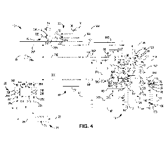
each other in the axial direction. For example, the positioning grooves 31 and
33 shown
in Fig. 2 are offset from each other in the axial direction. In order to allow
the movable
limiting bar 1 to freely extend, preferably, the at least one positioning
groove axially
extends through the fixing head 3. Since the connecting ear is configured to
expand
radially and outwardly and thus fall off the positioning groove during the
release of the
valve stent, the positioning groove opens radially and outwardly. In other
words, the
positioning groove includes a radial opening area. In a loaded configuration
of the valve
stent, the movable limiting bar 1 blocks at the radial opening area of the
positioning
portion 30, and closes the radial opening area in a complete or partial manner
to prevent
the connecting ear 81 from expanding radially and outwardly and thus falling
off the
positioning portion (i.e., the positioning groove 33 in the present
embodiment).
21
Date Recue/Date Received 2020-09-15
CA 03097180 2020-09-15
[0137] The positioning groove in Fig. 2 includes an axial extending area
through the
fixing head 3 and two branched areas extending from two sides of the axial
extending
area respectively, which fits the T-shaped connecting ear in a form-fit
manner. The
movable limiting bar 1 extends through the axial extending area of the
positioning groove
to a distal end of the mounting portion for the implantable instrument. The
movable
limiting bar 1 shown in Fig. 2 assumes an unloaded configuration, and the
terminal end
11 axially extends to an outer periphery of the guiding head 2.
[0138] As shown in Fig. 2, when the movable limiting bar 1 extends axially and
straight,
the distal end of the movable limiting bar 1 extends to the guiding head 2.
When
cooperating with the implantable instrument, the movable limiting bar 1 can
also serve
as a slide rail between the implantable instrument and the outer sheath, and
function to
guide. Preferably, without constraint from the outer sheath, the distal end of
the movable
limiting bar 1 expands and turns radially and outwardly, as shown in Fig. 1,
so as to
ensure the release of the implantable instrument, and to reduce unexpected
radial
obstruction from the movable limiting bar I. The movable limiting bar 1 may be
preset
and expands radially and outwardly when the outer sheath is released.
Alternatively, at
least a part of the movable limiting bar 1 has a deformable structure that is
made of
flexible material and/or is formed as an articulated mechanism.
[0139] The starting end of the movable limiting bar 1 may be fixed with other
parts by
bonding, binding, locking, or welding, or may be formed in one piece with
other parts. A
biocompatible and anticorrosion adhesive is preferred as the material for
bonding. A
flexible and corrosion-resistant binding wire is preferred as the material for
binding.
[0140] In the case of welding, a locker made of alloy material may be
connected to the
rear of the fixing head or the core tube, and then the starting end of the
movable limiting
bar 1 may be tightly locked by the locker. As shown in Fig. 3 which only shows
a part of
the extending section 12, the starting end 13 of the movable limiting bar 1 is
locked in
the locker 14 that is made of stainless steel (316 stainless steel material).
The locker 14
is connected on the fixing head 3 or the core tube 7 by welding.
[0141] Within the delivery device, as shown in Figs. 1 and 2 in which the
implantable
instrument such as an implantable heart valve is not shown, the movable
limiting bar 1
assumes the unloaded configuration. After the implantable instrument is
loaded, the
movable limiting bar 1 transforms into a loaded configuration in which the
movable
limiting bar 1 applies force to a connecting portion of the implantable
instrument under
the constraint of the outer sheath. For example, the movable limiting bar 1
can prevent
22
Date Recue/Date Received 2020-09-15
CA 03097180 2020-09-15
the connecting ear of the implantable heart valve from falling off the
positioning groove.
The movable limiting bar also has a released configuration, in which the
implantable
instrument falls off the outer sheath and the movable limiting bar starts to
release, and
the applied force from the outer sheath through the movable limiting bar to
the connecting
portion of the implantable instrument is released. For example, when the outer
sheath is
withdrawn and the implantable heart valve is released, the force from the
outer sheath
through the movable limiting bar to the connecting ear of the implantable
heart valve is
released, and in the meantime, the valve stent radially expands and the
connecting ear
falls off the positioning groove.
[0142] The movable limiting bar 1 may be configured as a long strip with a
solid or
hollow structure. In the present embodiment, the movable limiting bar 1 is
configured as
a flat strip with a solid structure. As shown in Fig. 4, the terminal end 11
of the movable
limiting bar 1 may be configured as an arc-shaped structure instead of a
structure with
sharp corners.
[0143] Each movable limiting bar 1 has a length of 10 mm to 80 mm, a width of
1 mm
to 2 mm, and a thickness of 0.2 mm to 0.5 mm. In the case where the movable
limiting
bar 1 has a maximum length, the entire movable limiting bar 1 should be able
to be
received in the outer sheath 5, and the terminal end of the movable limiting
bar 1 extends
to the distal end of the valve stent 8. In the loaded configuration, the
movable limiting bar
1 should be long enough to cover the entire valve stent 8 so that the outer
sheath 5 may
be pushed and withdrawn without direct contacting with the valve stent 8.
[0144] Referring to Figs. 5A to 5D, in order to ensure that the movable
limiting bar 1
has a small dynamic friction factor, the movable limiting bar 1 is preferably
made of PTFE
material. Each movable limiting bar 1 shown in Figs. 5A to 5D has a length of
65 mm, a
width adapted to be suited to the width of the positioning groove of the
fixing head 3, and
a thickness of 0.5 mm. When the movable limiting bars 1 are in a constrained
condition,
three movable limiting bars 1 axially extend through respective positioning
grooves and
further to the distal ends thereof, respectively. The valve stent 8 includes
three T-shaped
connecting ears. In order to fit the shape of the connecting ear, the
positioning groove
axially extends through the fixing head 3 and forms a crossing groove. In
order to ensure
that the constraint is effective, the axial extending area of the positioning
groove is
completely closed by a respective movable limiting bar I. In other words, the
width of the
movable limiting bar 1 corresponds to the width of the axial extending area.
In the case
where the axial extending area axially extends with unequal widths at
different positions,
23
Date Recue/Date Received 2020-09-15
CA 03097180 2020-09-15
the width of the movable limiting bar 1 should at least correspond to the
narrowest area
of the axial extending area to ensure that the movable limiting bar 1 can be
partially or
completely received in the positioning groove. The outer surface of the
movable limiting
bar 1 may slightly protrude from the outer periphery of the fixing head 3 to
reduce friction
between the outer periphery of the fixing head 3 and the inner wall of the
outer sheath 5.
[0145] Figs. 5A and 5B show loaded configurations of the implantable
instrument. Fig.
5A shows a loaded configuration of the implantable instrument 8 before being
released,
which is completely surrounded by the outer sheath 5. Fig. 5B shows a loaded
configuration of the implantable instrument 8 being partially released and
exposed. Figs.
5C and 5D show released configurations of the implantable instrument. Fig. 5C
shows a
released configuration of the valve stent which is completely exposed out of
the outer
sheath 5, and the proximal end of which is self-expanded and has not sprung
out yet,
and this configuration is a momentary configuration which appears and
disappears very
quickly. Fig. 5D shows a released configuration of the valve stent in which
the proximal
.. end of the valve stent has already sprung out completely. In the loaded
configuration of
the implantable instrument, the movable limiting bar 1 prevents the connecting
ear from
falling off the positioning portion.
[0146] As shown in Fig. 5A, when the valve stent 8 is loaded into the delivery
device,
the movable limiting bar 1 starts to surround the valve stent 8 from the
fixing head 3 to
receive the valve stent 8 in the outer sheath S. In the loaded configuration
of the
implantable instrument, the radial outer side of the movable limiting bar 1
abuts against
the inner wall of the outer sheath, and the radial inner side of the movable
limiting bar 1
limits the displacement of the connecting ear 81 from radially falling off the
positioning
groove.
[0147] As shown in Fig. 5B, during the release of the valve stent 8, the outer
sheath 5
is withdrawn and slides along the movable limiting bar 1, thereby avoiding
direct
contacting with the valve stent 8. The terminal end 11 and the extending
section 12 of
the movable limiting bar 1 expand together with the valve stent, and during
the gradual
release of the valve stent, the terminal end 11 of the movable limiting bar 1
transforms
from a configuration abutting against the valve stent 8 to an unfolded
configuration. The
outer sheath 5 is subsequently and gradually withdrawn along the movable
limiting bar
1 until the valve stent 8 is completely released. As the starting end 13 of
the movable
limiting bar 1 is fixed on the fixing head 3, the extending section 12 of the
movable limiting
bar 1 adjacent to the starting end 13 experiences a constraint force from the
starting end
24
Date Recue/Date Received 2020-09-15
CA 03097180 2020-09-15
13. In the case where the connecting ear of the valve stent 8 is inserted in
the positioning
groove 33 of the fixing head 3, the extending section of the movable limiting
bar 1
adjacent to the proximal end thereof abuts against the positioning groove 33,
and radially
and inwardly presses against the connecting ear of the valve stent 8, thereby
preventing
the connecting ear from prematurely falling off the positioning groove 33 of
the fixing
head 3 during the release of the valve stent 8, thereby avoiding a sudden
release of the
valve stent 8. During the release of the valve stent 8, if the valve stent is
placed at an
unexpected position and needs to be replaced, because of the constraint force
from the
movable limiting bar 1 to the connecting ear in the positioning groove 3, it
is possible to
push the outer sheath 5 along the movable limiting bar 1 to fold the released
portion of
the valve stent 8 and thus withdraw the valve stent 8.
[0148] As shown in Fig. 5C, the outer sheath 5 is offset from a projection of
the
proximal end of the positioning groove 33 of the fixing head 3 on an axis of
the outer
sheath. The movable limiting bar 1 is no longer constrained by the outer
sheath and does
not limit the radial displacement of the connecting ear of the valve stent,
which means
that the constraint force from the movable limiting bar 1 to the connecting
ear of the valve
stent 8 is released. In other words, the movable limiting bar 1 transforms
into the released
configuration and the valve stent 8 is allowed to expand and fall off the
positioning groove
33. The connecting ear shown in Fig. 5C has not radially sprung out yet, but
is ready to
radially spring out.
[0149] As shown in Fig. 5D, the connecting ear 81 of valve stent at the
proximal end
thereof has radially sprung out, and the movable limiting bar 1 is separated
from the
connecting ear.
[0150] Referring to Fig. 6, in another embodiment, the movable limiting bar 1
has a
short axial length, and the terminal end thereof is aligned with the distal
end of the fixing
head 3.
[0151] The movable limiting bar 1, shown in Figs. 1, 2 and 5A to 5D, has a
large size,
which not only constrains the implantable instrument, for example, by limiting
the radial
displacement of the connecting ear of the heart valve stent and thus
stabilizing the
engagement between the connecting ear and the positioning portion, but also
provides
a smooth rail between the valve stent 8 and the outer sheath 5 to reduce the
friction
therebetween. As the outer sheath 5 directly contacts the movable limiting bar
1, less
force from an operator is required during pushing or withdrawing of the outer
sheath 5
so as to precisely control the release and the retraction of the valve stent
8.
Date Recue/Date Received 2020-09-15
CA 03097180 2020-09-15
[0152] Three movable limiting bars 1 are shown in Fig. 6 which are configured
as long
strips with solid structures and are made of PTFE material. The starting end
of the
movable limiting bar 1 is fixed to the rear of the fixing head 3 at the
proximal end thereof
by bonding, and the terminal end of the movable limiting bar 1 is aligned with
the distal
end of the fixing head 3. In other words, the movable limiting bar 1 should at
least
completely cover the respective connecting ear and constrain it in the
positioning groove.
The width of the movable limiting bar 1 corresponds to the width of the axial
extending
area of the positioning groove 33. The movable limiting bar 1 has a thickness
of 0.5 mm.
[0153] Referring to Figs. 7A to 7E, in a further embodiment, the implantable
instrument
8 has an unreleased configuration which is completely surrounded by the outer
sheath
5, a partial released configuration which is partially exposed out of the
outer sheath 5,
and a released configuration which is completely exposed out of the outer
sheath 5,
wherein when the implantable instrument 8 is in either an unreleased
configuration or a
partial released configuration, the movable limiting bars 1 are in loaded
configurations.
[0154] In this embodiment, the valve stent 8 is provided with connecting ears
81. After
the valve stent 8 is loaded into the delivery device, the movable limiting bar
1 extends to
a position where the distal end of the movable limiting bar 1 is aligned with
the distal end
of the fixing head 3, and the terminal end of the movable limiting bar 1 is
only capable of
abutting against the connecting ear which is inserted in the positioning
groove 33 of the
fixing head. After the valve stent 8 is delivered into the human body, it will
be gradually
released by withdrawing the outer sheath 5. In the meantime, the connecting
ear 81 of
the valve stent 8, which has already been inserted in the positioning groove
33 of the
fixing head, will be firmly constrained in the positioning groove 33 under the
constraint
of the starting end of the movable limiting bar 1, thereby preventing the
stent from being
completely released in advance under the influence of the expansion force from
the
released portion of the valve stent 8 to the connecting ear.
[0155] The movable limiting bar 1 with small size avoids influence to the
normal
release of the stent and undesired constraint to the stent. The movable
limiting bar 1
may also extend to the axial middle area of the valve stent 8. For example,
the movable
limiting bar 1 may extend no more than the axial largest area of the valve
stent which
has already been completely released, such as the area indicated by the point
A shown
in Fig. 7H.
[0156] Fig, 7A shows the outer sheath 5, in which the valve stent 8 is in the
unreleased
configuration.
26
Date Recue/Date Received 2020-09-15
CA 03097180 2020-09-15
[0157] Referring to Fig, 7B, after the valve stent 8 is delivered into the
human body, it
will be gradually released by withdrawing the outer sheath 5. In the meantime,
the
connecting ear 81 of the valve stent 8, which has already been inserted in the
positioning
groove 33 of the fixing head, will be firmly constrained in the positioning
groove 33 under
the constraint of the starting end of the movable limiting bar 1, thereby
preventing the
stent from being completely released in advance under the influence of the
expansion
force from the released portion of the valve stent 8 to the connecting ear.
[0158] Referring to Fig. 7C, after the outer sheath 5 is withdrawn, the outer
sheath 5
is offset from a projection of the positioning groove 33 on an axis of the
outer sheath.
The movable limiting bar 1 is no longer constrained by the outer sheath, which
means
that the constraint force from the movable limiting bar 1 to the valve stent 8
is released.
In other words, the movable limiting bar 1 is in the released configuration
and the valve
stent 8 is allowed to expand and fall off the positioning groove 33. The
configuration
shown in Fig. 7C is a momentary configuration which appears and disappears
very
quickly, and the connecting ear has not radially sprung out yet, but is ready
to radially
spring out.
[0159] The loaded configuration in the present disclosure refers to the
configuration in
which the connecting portion of the implantable instrument is engaged with the
positioning portion. In particular, the loaded configuration may refer to the
configuration
in which the implantable instrument is assembled into the positioning portion.
The
released configuration refers to the configuration in which the connecting
portion of the
implantable instrument is allowed to fall off the positioning portion. It
should be noted that
the released configuration does not refer to the configuration in which the
implantable
instrument has already been completely released, but refer to the
configuration in which
the engagement between the connecting portion and the positioning portion is
releasable.
As to the remaining portion of the implantable instrument that is not
configured for
engaging with the positioning portion, it may have already been partially or
completely
released and expanded radially in the released configuration.
[0160] Referring to Fig. 7D, the connecting ear 81 pushes the movable limiting
bars 1
that is radially deformable to radially spring out, and the movable limiting
bars 1
subsequently turn outwardly. Referring to Fig. 7E, the movable limiting bars 1
return to
and contact with the fixing head 3.
[0161] Referring to Figs. 7F, 7G and 7H, in another embodiment, in order to
ensure
that the movable limiting bars 1 have a small dynamic friction factor, the
movable limiting
27
Date Recue/Date Received 2020-09-15
CA 03097180 2020-09-15
bar 1 is preferably made of PTFE material. Each movable limiting bar 1 in
Figs. 7F to 7H
has a length of 15 mm, a width adapted to suit the width of the fixing head 3
for the stent,
and a thickness of 0.5 mm. When the movable limiting bars 1 are in a
constrained
condition, three movable limiting bars 1 axially extend through respective
positioning
grooves and further to the distal ends thereof, respectively. The valve stent
8 includes
three T-shaped connecting ears. In order to fit the shape of the connecting
ear, the
positioning groove axially extends through the fixing head 3 and forms a
crossing groove.
In order to ensure that the constraint is effective, the axial extending area
of the
positioning groove is completely closed by a respective movable limiting bar
1. In other
words, the width of the movable limiting bar 1 corresponds to the width of the
axial
extending area. In the case where the axial extending area axially extends
with unequal
widths at different positions, the width of the movable limiting bar 1 should
at least
correspond to the narrowest area of the axial extending area to ensure that
the movable
limiting bar 1 can be received in the positioning groove in a partial or
complete manner.
The outer surface of the movable limiting bar 1 may slightly protrude from the
outer
periphery of the fixing head 3 to reduce friction between the outer periphery
of the fixing
head 3 and the inner wall of the outer sheath 5.
[0162] After the valve stent 8 is loaded into the delivery device, the movable
limiting
bars 1 are received in the outer sheath 5 together with the valve stent 8
which is
surrounded by the movable limiting bars 1. In other words, the implantable
instrument
has an unreleased configuration which is completely surrounded by the outer
sheath, in
which the movable limiting bars 1 are in the loaded configurations. During the
release of
the valve stent 8, as shown in Fig. 7F, the outer sheath 5 is withdrawn and
slides along
the movable limiting bars 1 in the direction indicated by the arrow M, and in
the meantime,
the movable limiting bars 1 are in a working state. When the connecting ears
81 are
located in the outer sheath 5, the movable limiting bars 1 act on the
connecting ears 81
under the constraint of the outer sheath 5, thereby preventing the connecting
ears 81
from springing out.
[0163] As shown in Fig. 7G, the outer sheath 5 is further withdrawn in the
direction
indicated by the arrow M. The terminal end 101 of the movable limiting bar 1
at the distal
end is free of the constraint of the outer sheath 5, while the extending
section 102 and
the connecting ear of the valve stent are still located in the outer sheath 5.
The extending
section 102 acts on the connecting ear 81, and thus the connecting ear 81 is
free of the
great expansion force from the expanding stent during release and firmly
clamped in the
28
Date Recue/Date Received 2020-09-15
CA 03097180 2020-09-15
positioning groove 33 of the fixing head 3 for the stent. In other words, the
extending
section 102 acts on the connecting ear 81 and provides a radial pressing force
to the
connecting ear 81 of the valve stent 81 so that the connecting ear of the
valve stent is
secured in a stable manner, and free of the great expansion force from the
expanding
stent during release, and thus firmly clamped in the positioning groove 33 of
the fixing
head 3 for the stent, thereby avoiding the risk of falling off the positioning
portion of the
fixing head and a subsequent undesired complete release.
[0164] In the case where the valve stent is released at an undesired position,
the stent
can be retracted in the opposite direction of arrow M by pushing the outer
sheath 5 for
re-release. Referring to Fig. 7H, if the valve stent is released at the
desired position, the
outer sheath 5 is further withdrawn in the direction of arrow M. The terminal
end 101 and
the extending end 102 of the movable limiting bar 1 are no longer constrained
by the
outer sheath 5, and they expand with the valve stent 8. At this time, the
movable limiting
bars 1 are in a non-working state. That is, there is no force applied to the
connecting
ears 81 so that the valve stent 8 can be completely released.
[0165] It should be noted that the working state here refers to that where the
movable
limiting bars 1 are in the loaded configurations. The non-working state refers
to that
where the movable limiting bars 1 are in the released configurations, in which
the force
from the outer sheath through the movable limiting bars 1 to the connecting
portions of
the implantable instrument is released after the implantable instrument is
transformed
into the released configuration. For example, when the implantable heart valve
stent is
released by withdrawing the outer sheath, the force from the outer sheath
through the
movable limiting bars 1 to the connecting ears of the implantable heart valve
stent is
released; in the meantime, the connecting ears of the valve stent expand
radially and fall
off the positioning grooves.
[0166] During the release, if the valve stent is released at an undesired
position, the
valve stent 8 can be retracted into the outer sheath 5 in the opposite
direction of arrow
M by pushing the outer sheath 5 for retrieval and re-release.
[0167] Compared to the prior art, the valve stent here can be retracted in a
stable
manner, so that it can be retracted into the sheath for re-release or
retrieval in the case
where the valve stent is released at an undesired position during release. A
stable
retracting force is the key to retracting the valve stent into the outer
sheath 5. Due to the
movable limiting bars 1 which serve as a spacer, the connecting ears 81 can be
received
in the positioning groove 33 in a stable manner, and the valve stent can be
retracted into
29
Date Recue/Date Received 2020-09-15
CA 03097180 2020-09-15
the outer sheath with the movement of the outer sheath which provides a strong
force to
the valve stent.
[0168] It should be noted that, during release, even though the implantable
instrument
is exposed partially, i.e., the implantable instrument is in the partial
released configuration,
the movable limiting bars 1 are still in the loaded configurations.
[0169] If the valve stent is released at the desired position, the outer
sheath 5 is further
withdrawn in the direction of arrow M and becomes the configuration shown in
Fig. 7H.
The terminal end 101 and the extending end 102 of the movable limiting bar 1
are no
longer constrained by the outer sheath 5, and they expand with the valve stent
8. At this
time, the movable limiting bars 1 are in the released configurations. That is,
there is no
force applied to the connecting ears 81 so that the valve stent 8 can be
completely
released. When the valve stent 8 is completely released, the radial pressing
force from
the movable limiting bars 1 to the connecting ears is released with the
withdrawal of the
outer sheath 5, and the movable limiting bars 1 would not obstruct the
released valve
stent, thereby avoiding a displacement of the valve stent.
[0170] Referring to Figs. 8, 9 and 10, in other embodiments, the inner wall of
the outer
sheath 5 at the distal end is provided with at least one fixing and guiding
bar 10.
[0171] Other than the movable limiting bar 1, the guiding head 2, the fixing
head 3, the
inner sheath 4, the outer sheath 5, and the valve stent 8 illustrated in the
figures, the
fixing and guiding bar 10 is also provided at the inner wall of the outer
sheath 5. There
are three fixing and guiding bars 10 with the same length, which are evenly
arranged in
a spaced-apart manner in the circumferential direction and fixed on the inner
surface of
a tubular housing of the outer sheath 5 at the distal end, and provides smooth
rails
between the valve stent 8 and the outer sheath 5.
[0172] The fixing and guiding bars 10 are alternatively arranged with the
positioning
grooves of the fixing head 3 (and thus the movable limiting bars 1) in the
circumferential
direction. When the valve stent 8 is constrained in the outer sheath 5, the
proximal ends
of the fixing and guiding bars abut against the fixing head 3, and are
alternatively
arranged with the positioning grooves one after the other.
[0173] The fixing and guiding bar 10 is a solid flat strip with a length of 10
mm to 80
mm, a width of 1 mm to 2 mm, and with a thickness of 0.2 mm to 0.5 mm. In this
embodiment, the length of the fixing and guiding bar 10 corresponds to the
axial length
of the valve stent 8, and is designated to be about 60 mm.
Date Recue/Date Received 2020-09-15
CA 03097180 2020-09-15
[0174] The fixing and guiding bars 10 may be fixed with the inner wall of the
outer
sheath 5 by bonding, binding, locking, or welding, or may be formed in one
piece with
the inner wall of the outer sheath 5. The fixing and guiding bars 10 are made
of PTFE
material, and the portion thereof engaging with the implantable instrument 8
has a
smooth surface or a lubricating coating. In a preferred implementation, the
fixing and
guiding bars 10 are formed in one piece with the inner wall of the outer
sheath 5, and the
fixing and guiding bars 10 are configured as ribs protruding from the inner
surface of the
outer sheath 5 with smooth surfaces or lubricating coatings.
[0175] The fixing and guiding bars may cooperate with various movable limiting
bars
which have a different length from the fixing and guiding bars such as the
movable
limiting bars with a length shown in Figs. 1 and 2, or the short movable
limiting bars
shown in Figs. 6 and 7A to 7H. In particular, Fig. 10 shows an implantable
instrument in
a released configuration in which movable limiting bars and fixing and guiding
bars are
provided. In order to clearly show the connecting ears 81 of the valve stent 8
and the
movable limiting bars 1, the outer sheath 5 shown in Fig. 10 is withdrawn
until the
movable limiting bars are completely exposed. The configuration shown in Fig.
10 is a
momentary configuration which appears and disappears very quickly, and the
connecting
ears have not radially sprung out yet, but are ready to radially spring out.
[0176] Referring to Fig. 10, when the valve stent 8 is released, the outer
sheath 5
contacts with and slides on the valve stent 8 through the fixing and guiding
bar 10, so it
can be withdrawn subject to a very small friction force so as to gradually
release the
stent.
[0177] When the outer sheath 5 is withdrawn to the position where the fixing
head 3
is located, the valve stent 8 is only constrained in the outer sheath 5 at the
connecting
ears. At this time, the fixing and guiding bars 10 completely fall off the
valve stent 8, and
the movable limiting bars 1 press against the connecting ears under the
constraint of the
outer sheath 5. With a further withdrawal of the outer sheath 5, the
constraint force from
the movable limiting bars 1 to the connecting ears gradually decreases, and
the
connecting ears are gradually released. In summary, the valve stent 8 is
gradually
released based on the smooth rails and the radial inward pressing force
provided by the
fixing and guiding bars 10 and the movable limiting bars I. Due to the fixing
and guiding
bars 10 which provides smooth rails, and the movable limiting bars 1 which
fill the gap
between adjacent fixing and guiding bars, the friction between the outer
sheath 5 and
the valve stent in the compressed configuration is reduced, which facilitates
the release
31
Date Recue/Date Received 2020-09-15
CA 03097180 2020-09-15
or retraction of the valve stent from or into the outer sheath.
[0178] In a further development, some of the movable limiting bars 1 are
provided on
or in the positioning grooves of the fixing head and function to prevent the
connecting
ears of the stent from falling off the positioning grooves, the others are
provided on the
outer wall of the fixing head and serve as slide rails for the outer sheath
sliding thereon.
In a preferred implementation, the distal ends of the movable limiting bars 1
corresponding to the positioning grooves are aligned with the fixing head, or
do not
extend beyond the most distal end of the fixing head, or slightly extend
beyond the most
distal end of the fixing head.
[0179] The following embodiments mainly describe the length and shape of the
movable limiting bars 1 and the engagement for the connecting ears and the
fixing head,
and the other parts may refer to the above embodiments separately or in
combination.
[0180] Referring to Figs. 11A and 11B, the connecting ear 81 is T-shaped, and
the
positioning portion of the fixing head 3 is configured as a positioning groove
33. In the
loaded configuration, the connecting ear 81 is inserted in the positioning
groove 33 that
has a shape corresponding to the connecting ear 81. The movable limiting bar 1
is
overlapped and pressed on the connecting ear 81 under the constraint of the
outer
sheath to prevent the connecting ear 81 from falling off the positioning
groove 33. During
the release of the stent, the constraint on the connecting ear 81 is not
released until the
outer sheath is completely separated from the movable limiting bar 1.
[0181] The positioning groove 33 has an appropriate depth that is no less than
the
thickness of the connecting ear which allows the connecting ear 81 to be
radially inserted
(received) in the positioning groove 33.
[0182] In other preferred embodiments, both the movable limiting bar 1 and the
connecting ear 81 can be received in the positioning groove in an overlapping
manner
one on top of the other, and the positioning groove 33 has an appropriate
depth which is
equal to the sum of the thicknesses of the connecting ear and the movable
limiting bar
1, so that the outer surface of the movable limiting bar 1 in the loaded
configuration is
aligned with the outer wall of the fixing head 3 in the radial direction.
[0183] Referring to Figs. 12A to 12D, the connecting ear 81 is U-shaped. One
side of
the U-shaped opening is connected with the stent and closed. The positioning
portion of
the fixing head 3 is a positioning protrusion 34. The connecting ear 81 is
extended around
the positioning protrusion 34 with the U-shaped structure thereof to achieve
its axial
32
Date Recue/Date Received 2020-09-15
CA 03097180 2020-09-15
positioning. In order to prevent the connecting ear 81 from radially
protruding too much,
a recess 35 is provided around the outer periphery of the positioning
protrusion 34, i.e.,
on the outer wall of the fixing head 3. The connecting ear 81 is received in
the recess 35
in such a manner that the outer surface of the connecting ear 81 is aligned
with the outer
wall of the fixing head 3 in the radial direction.
[0184] In other preferred embodiments, both the movable limiting bar 1 and the
connecting ear 81 can be received in the recess 35 in an overlapping manner
one on top
of the other, and the recess 35 has an appropriate depth which is equal to the
sum of the
thicknesses of the connecting ear and the movable limiting bar 1, so that the
outer
surface of the movable limiting bar 1 in the loaded configuration is aligned
with the outer
wall of the fixing head 3 in the radial direction.
[0185] Referring to Fig. 12B, the movable limiting bar 1 has a branched
structure which
is U-shaped, with the branches extending towards the distal end and
overlapping on the
outer side of the connecting ear 81, and the connection portion of the
branches fixed on
the outer side of the fixing head 3.
[0186] Referring to Fig. 12C, the movable limiting bar 1 is configured as a
single strip,
and also extends towards the distal end and overlaps the outer side of the
connecting
ear 81.
[0187] Referring to Fig. 12D, the movable limiting bar 1 has a branched
structure
which is V-shaped or Y-shaped, with the branches extending towards the distal
end and
overlapping the outer side of the connecting ear 81, and the connection
portion of the
branches fixed on the outer side of the fixing head 3.
[0188] Figs. 13A to 13D illustrate configurations in which the connecting ear
is pressed
by various movable limiting bars 1 with different lengths. In the loaded state
of the
implantable heart valve stent, the movable limiting bar 1 is constrained by
the outer
sheath 5 and positions the connecting ear 81 on the outer side of the fixing
head. The
positioning protrusion 34 is shown as an example of the positioning portion of
the fixing
head, and at least a part of the distal end of the movable limiting bar 1
overlaps and
presses on the connecting ear 81.
[0189] Referring to Fig. 13A, the distal end of the movable limiting bar 1
overlaps and
presses on the connecting ear 81, and does not extend to the positioning
protrusion 34.
The distal end of the movable limiting bar 1 only overlaps and presses on a
small area
of the connecting ear 81.
33
Date Recue/Date Received 2020-09-15
CA 03097180 2020-09-15
[0190] Referring to Fig. 13B, the distal end of the movable limiting bar 1
overlaps and
presses on the connecting ear 81, and at least axially extends to completely
cover the
positioning portion of the fixing head. In other words, the distal end of the
movable limiting
bar 1 extends beyond the positioning protrusion 34 to the distal end of the
fixing head 3.
The axial distal end of the movable limiting bar 1 overlaps and presses on the
connecting
ear 81 and the entire fixing head 3.
[0191] Referring to Fig. 13C, the distal end of the movable limiting bar 1
overlaps and
presses on the connecting ear 81. The distal end of the movable limiting bar 1
axially
extends beyond the fixing head.
[0192] Referring to Fig. 13D, the distal end of the movable limiting bar 1
overlaps and
presses on the connecting ear 81. The distal end of the movable limiting bar 1
axially
extends beyond the fixing head to the portion of the implantable heart valve
stent with
the greatest diameter. Considering that the outer diameter of the implantable
heart valve
stent in the loaded configuration remains substantially unchanged due to the
constraint
of the outer sheath, the portion of the implantable heart valve stent with the
greatest
diameter may be regarded as the portion of the released implantable heart
valve stent
with the greatest diameter.
[0193] The embodiments are described taking the heart valve stent as an
example of
the implantable instrument. It would be appreciated for a person skilled in
the art that
other implantable instruments can also be delivered into the corresponding
sites of the
human body by the delivery device disclosed here.
[0194] The features described in the above various embodiments may be
combined.
In order to simplify the descriptions, not all possible combinations of the
features in the
above embodiments have been described. However, any combinations of the
features
should be within the scope of the disclosure as long as no conflict resides
between these
features.
[0195] The above embodiments are only several implementations of the present
disclosure which are described specifically and in detail, without limitation
to the scope
claimed by the present disclosure. Those skilled in the art can make various
modifications and variations to the embodiments without departing from the
spirit and
scope of the present disclosure. Obviously, these modifications and variations
should fall
into the scope claimed by the present disclosure. Therefore, the scope of the
disclosure
shall be subject to the appended claims.
34
Date Recue/Date Received 2020-09-15