Note: Descriptions are shown in the official language in which they were submitted.
CA 03097541 2020-10-15
WO 2019/236589
PCT/US2019/035401
COMBINATION OF DISSOLVED AIR FLOTATION AND FIXED FILM BIOREACTOR
SOLUTIONS
CROSS-REFERENCE TO RELATED APPLICATIONS
This application claims the benefit under 35 U.S.C. 119 of U.S. Patent
Application
No. 62/680,764, titled "Enhancement to Captivator System for Biological
Nutrient Removal,"
filed on June 5, 2018, which is incorporated herein by reference in its
entirety for all
purposes.
FIELD OF TECHNOLOGY
Aspects and embodiments disclosed herein are directed toward systems and
methods
for the treatment of wastewater.
SUMMARY
In accordance with an aspect, there is provided a wastewater treatment system.
The
wastewater treatment system comprises a contact tank having a first inlet
fluidly connectable
to a source of wastewater to be treated, a second inlet, and an outlet, the
contact tank
configured to treat the wastewater with waste sludge to form a mixed liquor.
The wastewater
treatment system may comprise a dissolved air flotation unit having a first
inlet fluidly
connected to the outlet of the contact tank, a second inlet fluidly
connectable to a source of
gas, a floated solids outlet, and an effluent outlet, the dissolved air
flotation unit configured to
treat the mixed liquor with the gas to form floated solids and an effluent.
The wastewater
treatment system may comprise a fixed film reactor having a first inlet
fluidly connected to
the effluent outlet of the dissolved air flotation unit, a second inlet, and
an outlet, the fixed
film reactor configured to form a fixed film effluent and a solid-liquid
separation apparatus
having an inlet fluidly connected to the outlet of the fixed film reactor, an
effluent outlet, and
a waste sludge outlet in fluid communication with the second inlet of the
contact tank and the
second inlet of the fixed film reactor.
In some embodiments, the fixed film reactor is an aerobic biological reactor.
In some embodiments, the fixed film reactor comprises media positioned within
an
aeration tank.
In some embodiments, the fixed film reactor comprises at least one of a
trickling
filter, a rotating biological contactor, and a moving bed biological reactor.
In some embodiments, the fixed film reactor comprises a media disk or a panel
1
CA 03097541 2020-10-15
WO 2019/236589
PCT/US2019/035401
In some embodiments, the fixed film reactor comprises randomly packed moving
media.
In some embodiments, the wastewater treatment system further comprises a
sludge
mixing tank having a first inlet fluidly connected to the waste sludge outlet
of the solid-liquid
separation apparatus and an outlet fluidly connected to the second inlet of
the contact tank.
In some embodiments, the wastewater treatment system further comprises the
sludge
mixing tank having a second inlet fluidly connected to the floated solids
outlet of the
dissolved air flotation unit.
In some embodiments, the sludge mixing tank has a third inlet fluidly
connectable to a
source of oxygen.
In some embodiments, the wastewater treatment system further comprises a
screen
positioned between the source of wastewater and the contact tank
In some embodiments, the fixed film effluent comprises about 50 mg/L to about
300
mg/L of biological solids.
In some embodiments, the dissolved air flotation unit effluent has between
about 60%
to about 70% less TSS than the source of wastewater.
In some embodiments, the fixed film effluent has at least about 20% less BOD
than
the dissolved air flotation unit effluent.
In accordance with another aspect, there is provided a method for treating
wastewater.
The method may comprise introducing the wastewater and a waste sludge into a
contact tank
and mixing the wastewater with the waste sludge in the contact tank to form a
mixed liquor.
The method may comprise directing at least a portion of the mixed liquor to a
dissolved air
flotation unit and separating the mixed liquor to form a dissolved air
flotation unit effluent
and waste biosolids. The method may comprise directing the dissolved air
flotation unit
effluent to a fixed film reactor and biologically treating the dissolved air
flotation unit
effluent to form a fixed film effluent. The method may comprise directing the
fixed film
effluent to a solid-liquid separation apparatus and separating the fixed film
effluent to form a
solids-lean effluent and the waste sludge. The method may comprise selectively
recycling a
first portion of the waste sludge to the contact tank and a second portion of
the waste sludge
to the fixed film reactor. The method may comprise directing the solids-lean
effluent to a
treated wastewater outlet.
In some embodiments, the method may further comprise recycling at least a
portion of
the waste biosolids to the contact tank.
2
CA 03097541 2020-10-15
WO 2019/236589
PCT/US2019/035401
In some embodiments, the method may further comprise introducing the waste
sludge
into a first region of the contact tank and introducing the wastewater into a
second region of
the contact tank, the first region positioned upstream from the second region.
In some embodiments, the method may further comprise introducing a source of
oxygen into the first region of the contact tank.
In some embodiments, the method may further comprise separating non-biological
waste solids from the wastewater.
In some embodiments, the method may further comprise introducing at least one
of a
coagulant, a flocculant, or a ballast material to the fixed film effluent.
In some embodiments, the method may further comprise separating the ballast
from
the fixed film effluent.
In some embodiments, separating the mixed liquor in the dissolved air
flotation unit
may comprise reducing TSS by between about 60% and about 70%.
In some embodiments, biologically treating the dissolved air flotation unit
effluent
may further comprise reducing BOD by at least 20%.
In accordance with another aspect, there is provided a method of retrofitting
a
wastewater treatment system. The method may comprise providing a contact tank.
The
method may comprise providing a dissolved air flotation unit. The method may
comprise
fluidly connecting the contact tank to a source of wastewater. The method may
comprise
fluidly connecting the contact tank to an inlet of the dissolved air flotation
unit. The method
may comprise fluidly connecting the dissolved air flotation unit to an inlet
of the fixed film
reactor. The method may comprise fluidly connecting the contact tank to an
outlet of the
solid-liquid separation apparatus.
In some embodiments, the method of retrofitting may further comprise providing
a
sludge mixing tank and fluidly connecting the sludge mixing tank to a source
of waste sludge,
a source of oxygen, and an inlet of the contact tank.
In some embodiments, the method of retrofitting may further comprise
connecting the
sludge mixing tank to an outlet of the fixed film reactor.
In some embodiments, the method of retrofitting may further comprise fluidly
connecting the sludge mixing tank to an outlet of the solid-liquid separation
apparatus.
In some embodiments, the method of providing the contact tank and dissolved
air
flotation unit may reduce footprint of the wastewater treatment system when
replacing a
primary treatment subsystem.
3
CA 03097541 2020-10-15
WO 2019/236589
PCT/US2019/035401
In some embodiments, the method of retrofitting may further comprise providing
a
sensor.
In some embodiments, the method of retrofitting may further comprise providing
a
controller programmable to instruct a metering valve to selectively direct a
first portion of
waste sludge from the solid-liquid separation apparatus to the contact tank
and a second
portion of the waste sludge to the fixed film reactor responsive to a
measurement obtained by
the sensor and electrically connect the controller to the metering valve.
In accordance with another aspect, there is provided a method of facilitating
increased
operating efficiency of a wastewater treatment system comprising a fixed film
reactor and a
solid-liquid separation apparatus. The method may comprise providing a
dissolved air
flotation unit fluidly connected downstream from a source of wastewater and
upstream from
the fixed film reactor. The method may comprise instructing a user to operate
the dissolved
air flotation unit to generate floated biosolids and a dissolved air flotation
unit effluent. The
method may comprise instructing the user to direct at least a portion of the
dissolved air
flotation unit effluent to the fixed film reactor. The method may comprise
instructing the user
to selectively direct a first portion of waste sludge of the solid-liquid
separation apparatus to
the contact tank and a second portion of the waste sludge to the fixed film
reactor.
In some embodiments, the method of facilitating increased operating efficiency
of a
wastewater treatment system may further comprise providing a contact tank
fluidly connected
to the source of wastewater and upstream from the dissolved air flotation
unit.
In some embodiments, the method of facilitating increased operating efficiency
of a
wastewater treatment system may further comprise instructing the user to
direct at least a
portion of the floated biosolids to the contact tank.
BRIEF DESCRIPTION OF DRAWINGS
The accompanying drawings are not intended to be drawn to scale. In the
drawings,
each identical or nearly identical component that is illustrated in various
figures is represented
by a like numeral. For purposes of clarity, not every component may be labeled
in every
drawing. In the drawings:
FIG. 1 is a block flow diagram of a wastewater treatment system in accordance
with
an embodiment;
FIG. 2 is a block flow diagram of a wastewater treatment system in accordance
with
another embodiment;
4
CA 03097541 2020-10-15
WO 2019/236589
PCT/US2019/035401
FIG. 3 is a block flow diagram of a wastewater treatment system in accordance
with
another embodiment;
FIG. 4 is a block flow diagram of a wastewater treatment system in accordance
with
another embodiment;
FIG. 5 is a block flow diagram of a wastewater treatment system in accordance
with
another embodiment;
FIG. 6 is a block flow diagram of a wastewater treatment system in accordance
with
another embodiment;
FIG. 7 is a block flow diagram of a wastewater treatment system in accordance
with
another embodiment;
FIG. 8 is a block flow diagram of a wastewater treatment system in accordance
with
another embodiment;
FIG. 9 is a block flow diagram of a wastewater treatment system in accordance
with
another embodiment;
FIG. 10 is a block flow diagram of a wastewater treatment system in accordance
with
another embodiment;
FIG. 11 is a block flow diagram of a wastewater treatment system in accordance
with
another embodiment;
FIG. 12 is a graph of TSS removal by a method of treating wastewater in
accordance
with an embodiment; and
FIG. 13 is a graph of sBOD removal by a method of treating wastewater in
accordance with an embodiment.
DETAILED DESCRIPTION
This invention is not limited in its application to the details of
construction and the
arrangement of components set forth in the following description or
illustrated in the
drawings. The invention is capable of other embodiments and of being practiced
or of being
carried out in various ways. Also, the phraseology and terminology used herein
is for the
purpose of description and should not be regarded as limiting. The use of
"including,"
"comprising," "having," "containing," "involving," and variations thereof
herein is meant to
encompass the items listed thereafter and equivalents thereof as well as
additional items.
As the term is used herein, an "upstream" unit operation refers to a first
unit operation
which is performed upon a fluid undergoing treatment prior to a second unit
operation.
Similarly, an "upstream" treatment vessel or portion thereof refers to a first
treatment vessel
CA 03097541 2020-10-15
WO 2019/236589
PCT/US2019/035401
or portion thereof in which a first unit operation is performed prior to a
second unit operation
performed in a second treatment vessel or portion thereof A "downstream" unit
operation
refers to a second unit operation which is performed upon a fluid undergoing
treatment
subsequent to a first unit operation. Similarly, a "downstream" treatment
vessel or portion
thereof refers to a second treatment vessel or portion thereof in which a
second unit operation
is performed subsequent to a first unit operation performed in a first
treatment vessel or
portion thereof An upstream unit operation and/or treatment vessel having an
outlet in
"direct fluid communication" with an inlet of a downstream unit operation
and/or treatment
vessel directs material output from the outlet of the upstream unit operation
and/or treatment
vessel into the inlet of the downstream unit operation and/or treatment vessel
without any
intervening operations performed on the material. A first unit operation
and/or treatment
vessel described herein as being in fluid communication with a second unit
operation and/or
treatment vessel should be understood as being in direct fluid communication
with the second
unit operation and/or treatment vessel unless explicitly described as
otherwise. Conduits
which provide fluid communication between a first and a second unit operation
and/or
treatment vessel are to be understood as providing direct fluid communication
between the
first and second unit operation and/or treatment vessel unless explicitly
described as
otherwise.
Various unit operations and/or treatment vessels disclosed herein separate
fluid and/or
sludge into a solids-rich portion and a solids-lean portion wherein the solid-
lean potion has a
lower concentration of solids than the solids-rich portion. As the term is
used herein, an
"effluent" of a unit operation and/or treatment vessel refers to the solids-
lean portion of the
separated fluid and/or sludge. "Recycle" of material refers to directing
material from an outlet
of a downstream unit operation and/or treatment vessel to an inlet of a unit
operation and/or
treatment vessel upstream of the downstream unit operation and/or treatment
vessel.
U.S. patent serial numbers 8,808,544 and 10,131,550, titled "Contact
Stabilization/Prime Float Hybrid" and "Enhanced Biosorption of Wastewater
Organics Using
Dissolved Air Flotation with Solids Recycle," respectively, are incorporated
herein by
reference in their entireties for all purposes.
Aspects and embodiments of the present invention are directed toward systems
and
methods for treating wastewater. As used herein the term "wastewater"
includes, for
example, municipal wastewater, industrial wastewater, agricultural wastewater,
and any other
form of liquid to be treated containing undesired contaminants. Aspects and
embodiments of
the present invention may be utilized for primary wastewater treatment,
secondary
6
CA 03097541 2020-10-15
WO 2019/236589
PCT/US2019/035401
wastewater treatment, or both. Aspects and embodiments of the present
invention may
remove sufficient contaminants from wastewater to produce product water that
may be used
for, for example, irrigation water, potable water, cooling water, boiler tank
water, or for other
purposes.
In some embodiments, the apparatus and methods disclosed herein provide
advantages with regard to, for example, capital costs, operational costs, and
environmental-
friendliness as compared to conventional fixed film wastewater treatment
systems. In some
embodiments a dissolved air flotation system is included in a main stream of
wastewater
entering a fixed film wastewater treatment system. The dissolved air
floatation system may
remove a significant amount of biological oxygen demand, for example,
particulate
biological oxygen demand, from wastewater prior to the wastewater entering the
fixed film
treatment portion of the wastewater treatment system, increasing operating
efficiency of the
fixed film treatment system. This provides for a reduction in the size of the
primary treatment
portion of the wastewater treatment system for a given wastewater stream as
compared to a
conventional fixed film wastewater treatment system and a commensurate reduced
capital
cost for the overall system. Utilization of the dissolved air flotation system
may also reduce
the requirement for aeration in the fixed film treatment portion of the
treatment system to
effect oxidation of the biological oxygen demand of the wastewater, reducing
operating costs.
The amount of waste sludge generated by the fixed film treatment portion of
the treatment
system may also be reduced, reducing the amount of waste which would need to
be disposed
of or otherwise further treated. The material removed from the wastewater in
the dissolved air
flotation system may be utilized to produce energy, for example, in the form
of biogas in a
downstream anaerobic digestion system. The biogas may be used to provide
salable energy
through combustion or through use in, for example, fuel cells.
In accordance with an embodiment there is provided a method of facilitating
increased operating efficiency of a wastewater treatment system. The method
comprises
configuring a dissolved air flotation (DAF) unit in a wastewater treatment
system in fluid
communication between a contact tank and a fixed film reactor to remove solids
from a
portion of a first mixed liquor output from the contact tank prior to the
portion of the first
mixed liquor entering the fixed film reactor and to recycle at least a portion
of the solids to
the contact tank, the recycle of the at least a portion of the solids to the
contact tank reducing
an amount of biological oxygen demand to be treated in the fixed film reactor
as compared to
the wastewater treatment system operating in the absence of recycling the at
least a portion of
the solids to the contact tank,.
7
CA 03097541 2020-10-15
WO 2019/236589
PCT/US2019/035401
In some embodiments, greater than 50% of the solids are recycled from the DAF
unit
to the contact tank.
In some embodiments, the wastewater treatment system comprises a combination
of
the DAF unit and the contact tank, which can result in a reduced size of a
treatment system
due to a reduced biochemical oxygen demand (BOD) load. A reduced BOD load may
allow
for a higher energy production in a waste sludge anaerobic digester and reduce
the aeration
requirements in the system.
As the term is used herein, an "aerobic digester" and an "anaerobic digester"
can
operate as shown in U.S. patent serial numbers 8,808,544 and 10,131,550,
titled "Contact
Stabilization/Prime Float Hybrid" and "Enhanced Biosorption of Wastewater
Organics Using
Dissolved Air Flotation with Solids Recycle," herein incorporated by reference
in their
entirety for all purposes.
In some embodiments, the method comprises recycling solids from the DAF unit
to
the contact tank in an amount sufficient to increase biogas production of an
anaerobic
digester of the wastewater treatment system having an inlet in fluid
communication with an
outlet of the DAF unit, at least a second portion of the solids removed in the
DAF unit being
directed into the anaerobic digester.
In some embodiments, the method comprises recycling solids from the DAF unit
to
the contact tank in an amount sufficient to reduce the energy consumption of
the wastewater
treatment system.
In accordance with an embodiment there is provided a wastewater treatment
system.
The wastewater treatment system comprises a contact tank having a first inlet,
a second inlet,
and an outlet and a dissolved air flotation tank having an inlet in fluid
communication with
the outlet of the contact tank, a first outlet, and a second outlet. The
wastewater treatment
system further comprises a fixed film reactor having a first inlet in fluid
communication with
the outlet of the dissolved air flotation tank, a second inlet, and an outlet.
The wastewater
treatment system further comprises a solid-liquid separation apparatus having
an inlet in fluid
communication with the outlet of the fixed film reactor, an outlet in fluid
communication
with the second inlet of the contact tank and with the second inlet of the
fixed film reactor.
A fixed film biological system may oxidize and reduce soluble substrate,
eliminating
impurities and producing solids. Fixed film processes may maintain biological
growth on a
surface or inert carrier or sheet. The fixed film treated effluent may contain
about 100
milligrams per liter (mg/1) to about 200 mg/1 of biological solids for a
typical wastewater. In
general, the amount of biological solids in the fixed film effluent is
dependent on influent
8
CA 03097541 2020-10-15
WO 2019/236589
PCT/US2019/035401
TSS and BOD. Examples of fixed film processes include, without limitation,
moving bed
bioreactors (MBBR's), trickling filters, and rotating biological contactors.
In a conventional
fixed film system, wastewater is filtered through a primary or coarse screen
and treated in a
primary clarification unit. Effluent of these primary processes or a raw
wastewater may enter
a fixed film biological system where soluble substrate is oxidized or reduced
to biological
solids in the form of slough from the fixed biomass on the inert carrier or
sheet of the fixed
film reactor. Aeration may be supplied in aerobic zones to supply oxygen and
mixing to the
system. Oxygen may be supplied directly from the atmosphere. Thus, in certain
embodiments, the fixed film reactor is substantially free of an active
aeration system.
In a fixed film system, generally, excess biomass sloughs off the media and is
removed in a secondary clarifier. The sludge that is collected on the bottom
of the clarifier
may be pumped out of the clarifier and disposed of as waste sludge. Unlike an
activated
sludge system, there typically is no return of the bottom clarifier sludge to
the fixed film
system. There may be no need to recycle waste sludge back to the fixed film
system because
the required amount of biomass is retained on the media. In anaerobic or
anoxic based
systems, mixers may be provided to maintain mixing throughout.
In accordance with certain embodiments, a fixed film system may be retrofitted
by
installing a dissolved air flotation unit and contact tank upstream from the
fixed film reactor.
The dissolved air flotation unit and contact tank may reduce footprint of the
fixed film
treatment system when replacing a primary clarifier. In some embodiments, the
dissolved air
flotation unit and contact tank may reduce footprint of the primary treatment
by at least about
50%. The dissolved air flotation unit and contact tank may reduce footprint of
the primary
treatment by at least about 55%, about 60%, about 65%, or about 70%.
In other embodiments, an existing primary clarifier can be repurposed as a
dissolved
air flotation unit to increase operating capacity of the treatment system.
Retrofitting an
existing primary clarifier into a dissolved air flotation unit may increase
operating capacity
by at least about five fold. In some embodiments, retrofitting the existing
primary clarifier
into a dissolved air flotation unit may increase operating capacity by at
least about 100%,
about 200%, about 300%, about 400%, about 500%, about 600%, or about 700%. In
certain
embodiments, retrofitting the existing primary clarifier into a dissolved air
flotation unit may
increase operating capacity at least 2 fold, at least 5 fold, at least 7 fold,
or at least 10 fold. In
an exemplary embodiment, a primary clarifier is operated at about 1000 gpd/ft2
and a
dissolved air flotation unit is operated at about 5000 gpd/ft2. Repurposing
the same
9
CA 03097541 2020-10-15
WO 2019/236589
PCT/US2019/035401
exemplary tank to be used as a dissolved air flotation unit will increase
operating capacity by
a factor of five.
Furthermore, because the solids are floated instead of settled, a dissolved
air flotation
primary treatment may remove a high degree of fats, oils, and grease (FOG)
from the
wastewater, reducing the load on the fixed film reactor. In some embodiments,
primary
treatment with the dissolved air flotation unit may reduce a load of FOG on
the fixed film
reactor by at least about 60% as compared to a primary clarifier. Retrofitting
a fixed film
wastewater treatment system with a dissolved air flotation unit may reduce a
load of FOG on
the fixed film reactor by at least about 60%, about 70%, about 80%, or about
90%.
The systems and methods of the present disclosure may be particularly
advantageous,
for example, in treatment plants where a small footprint is required such as,
for example, a
retrofit for industrial plants, small flow plants or package plants, hybrid
wastewater plants,
combining fixed film processes and activated sludge processes, and lagoon
plants requiring
nitrification. Also, this combination may be used in small flow systems that
do not have
significant operator interface yet require a high quality effluent. The use of
a fixed film
process in combination with a dissolved air flotation unit is not limited to
the examples given.
Many uses in biological and chemical treatment of wastewater or potable water
are possible.
The use of a dissolved air flotation system may benefit the existing fixed
film system
by removing a high percentage of particulate (suspended) BOD and lesser amount
of soluble
BOD. The retrofit generally reduces the size of the treatment system due to
reduced BOD
load, allows for higher energy production in a waste sludge anaerobic
digester, and reduces
aeration requirements. In general, the fixed film system does not operate with
activated
sludge. Instead, the dissolved air flotation system may use waste sludge from
the fixed film
system to adsorb soluble and particulate BOD in raw wastewater. Pilot testing
(described in
more detail below) with fixed film waste sludge shows similar removal of
particulate and
soluble BOD, as compared to activated sludge treatment.
The fixed film biological system may provide an effluent comprising biological
solids, often referred to as slough, which requires separation from a treated
effluent in a
downstream process. While fixed film processes have a small footprint,
effluent biological
solids from the process are often difficult to settle with conventional
sedimentation processes
frequently requiring a large settling area. Downstream clarification,
therefore, is often the
limiting step in the rate of wastewater treatment involving fixed film
biological systems or
fixed film reactors.
CA 03097541 2020-10-15
WO 2019/236589
PCT/US2019/035401
In accordance with some aspects of the method of treating wastewater, the DAF
unit
removes between about 60% and about 100% of suspended solids in the
wastewater. For
example, the DAF unit may remove at least about 60%, about 70%, about 80%,
about 90%,
or about 99% of the suspended solids in the wastewater. By providing primary
treatment with
a DAF unit, the load of suspended solids on the fixed film reactor may be
reduced, as
compared to primary treatment with a clarifier.
Similarly, in accordance with some aspects of the method of treating
wastewater, the
DAF unit removes between about 20% and about 80% of biological oxygen demand
in the
wastewater. For example, the DAF unit may remove at least about 20%, about
30%, about
40%, about 50%, about 60%, about 70%, or about 80% of BOD in the wastewater.
By
providing primary treatment with a DAF unit, the load of BOD on the fixed film
reactor may
be reduced, as compared to primary treatment with a clarifier.
According to certain embodiments, the systems and methods may include a
ballasted
solids-liquid separation downstream from the fixed film reactor. Ballasted
flocculation
systems or ballasted settling systems may comprise the addition of a
coagulant, ballast, and,
optionally, flocculant to improve the removal of dissolved, colloidal,
particulate and
microbiological solids. The precipitation and enhanced settlability of
ballasted solids
provides for a small clarification step, which may allow for a small footprint
system
comprising biological and clarification steps. According to embodiments of the
present
disclosure, ballasted flocculation systems may eliminate the need to provide a
secondary
clarifier directly downstream of a fixed film biological system or reactor.
Flocculation may be a process of contact and adhesion whereby particles and
colloids
in liquid such as a water or wastewater form larger-size clusters of material.
Particles may
cluster together into a floc. A flocculant may comprise a material or a
chemical that promotes
flocculation by causing colloids and particles or other suspended particles in
liquids to
aggregate, forming a floc. Polymer may be used as flocculants. For example,
acrylic acid/
acrylamide copolymers and modified polyacrylamides may be used.
Coagulation may be a process of consolidating particles, such as suspended
solids.
Coagulants may include cations, such as multivalent cations. They may include
cations such
as aluminum, iron, calcium or magnesium (positively charged molecules) that
may interact
with negatively charged particles and molecules that reduce the barriers to
aggregation.
Examples of coagulants include bentonite clay, polyaluminum chloride,
polyaluminum
hydroxychloride, aluminum chloride, aluminum chlorohydrate, aluminum sulfate,
ferric
chloride, and ferrous sulfate monohydrate.
11
CA 03097541 2020-10-15
WO 2019/236589
PCT/US2019/035401
In certain embodiments, a fixed film process followed by a ballasted
flocculation
process may be utilized for biological treatment of water or wastewater to
remove at least one
of nitrogen compounds, such as nitrates, biological oxygen demand (BOD),
chemical oxygen
demand (COD), and phosphorus compounds. Fixed film processes may reduce
nitrate to
nitrogen gas. Biological solids produced may then be removed in addition to
dissolved,
colloidal and particulate solids by the ballasted clarifiers. In certain
embodiments, at least one
of nitrogen compounds, such as nitrates, biological oxygen demand (BOD),
chemical oxygen
demand (COD), and phosphorus compounds may be removed prior to disinfection to
provide
potable water or drinking water to distribute it to a water supply grid.
In some embodiments, the fixed film reactor comprises media positioned within
an
aeration tank. The fixed film reactor may comprise at least one of a
stationary or moving
structure. For example, the fixed film reactor may comprise a stationary or
moving structure
as included in a trickling filter, a rotating biological contactor, or a
moving bed biological
reactor. The fixed film reactor may comprise a media disk or a panel to retain
biomass as a
film. The media disk may be, for example, a rotating disk. The fixed film
reactor may
comprise randomly packed moving media. The media may comprise, for example,
one or
more of plastic, sand, wood, rocks, or fabric. Exemplary plastic media
comprises polymers.
In certain embodiments, the media may include plasticizers as an additive.
Exemplary media
includes polyethylene, polyvinyl chloride, or polypropylene.
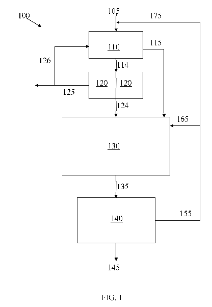
A first embodiment, indicated generally at 100, is illustrated in FIG. 1.
Wastewater
from a source of wastewater 105 is directed into a contact tank 110 through an
inlet of the
contact tank. In the contact tank 110, the wastewater is mixed with waste
sludge recycled
through a conduit 175 from a downstream fixed film reactor described below. In
some
embodiments, the contact tank 110 is aerated to facilitate mixing of the
wastewater and the
waste sludge. The aeration gas may be an oxygen containing gas, for example,
air. The
contact tank 110 may be provided with sufficient oxygen such that aerobic
conditions are
maintained in at least a portion of the contact tank 110. For example, the
contact tank 110
may be aerated. In other embodiments, the contact tank 110 may not be aerated.
Suspended
and dissolved solids in the wastewater, including oxidizable biological
materials (referred to
herein as Biological Oxygen Demand, or BOD), are adsorbed/absorbed into the
waste sludge
in the contact tank, forming a first mixed liquor. A portion of the BOD may
also be oxidized
in the contact tank 110. The residence time of the wastewater in the contact
tank may be
sufficient for the majority of the BOD to be adsorbed/absorbed by the waste
sludge, but not
so long as for a significant amount of oxidation of the BOD to occur. In some
embodiments,
12
CA 03097541 2020-10-15
WO 2019/236589
PCT/US2019/035401
for example, less than about 10% of the BOD entering the contact tank 110 is
oxidized in the
contact tank. The residence time of the wastewater in the contact tank is in
some
embodiments from about 30 minutes to about two hours, and in some embodiments,
from
about 45 minutes to about one hour. The residence time may be adjusted
depending upon
factors such as the BOD of the influent wastewater. A wastewater with a higher
BOD may
require longer treatment in the contact tank 110 than wastewater with a lower
BOD.
A first portion of the first mixed liquor formed in the contact tank is
directed into a
dissolved air flotation (DAF) system 120 through conduit 114. The DAF system
may include
a vessel, tank, or other open or closed containment unit configured to perform
a dissolved air
flotation operation as described below. For the sake of simplicity a dissolved
air flotation
system will be referred to herein as a "DAF unit." The DAF unit 120 may
function as both a
thickener and a clarifier. FIG. 1 illustrates two DAF units 120 operating in
parallel, however,
other embodiments may have a single DAF unit or more than two DAF units.
Providing
multiple DAF units provides for the system to continue operation if one of the
DAF units is
taken out of service for cleaning or maintenance.
Before entering the DAF unit(s), air or another gas may be dissolved in the
first mixed
liquor under pressure. The pressure may be released as the first mixed liquor
enters the DAF
unit(s) 120, resulting in the gas coming out of solution and creating bubbles
in the mixed
liquor. In some embodiments, instead of dissolving gas into the first mixed
liquor, a fluid, for
example, water having a gas, for example, air, dissolved therein, is
introduced into the DAF
unit(s) 120 with the first mixed liquor. Upon the mixing of the first mixed
liquor and the gas-
containing fluid, bubbles are produced. The bubbles formed in the DAF unit(s)
120 adhere to
suspended matter in the first mixed liquor, causing the suspended matter to
float to the
surface of the liquid in the DAF unit(s) 120, where it may be removed by, for
example, a
skimmer.
In some embodiments, the first mixed liquor is dosed with a coagulant, for
example,
ferric chloride or aluminum sulfate prior to or after introduction into the
DAF unit(s) 120.
The coagulant facilitates flocculation of suspended matter in the first mixed
liquor.
In the DAF unit(s) 120 at least a portion of the solids present in the
influent first
mixed liquor, including solids from the influent wastewater and from the waste
sludge, are
removed by a dissolved air flotation process. At least a portion of any oil
that may be present
in the first mixed liquor may also be removed in the DAF unit(s) 120. In some
embodiments,
a majority, for example, about 60% or more, about 75% or more, or about 90% or
more of the
suspended solids in the first mixed liquor introduced into the DAF unit(s) 120
is removed and
13
CA 03097541 2020-10-15
WO 2019/236589
PCT/US2019/035401
about 40% or more, for example, about 50% or more or about 75% or more of the
BOD is
removed. Removal of the BOD may include enmeshment and adsorption in the first
mixed
liquor and/or oxidation of the BOD and the formation of reaction products such
as carbon
dioxide and water. In other embodiments, up to about 100% of the suspended
solids is
removed in the DAF unit(s) 120 and a majority, for example, up to about 80% of
the BOD is
removed.
In some embodiments, suspended solids removed in the DAF unit(s) 120 are sent
out
of the system as waste solids through a conduit 125. These waste solids may be
disposed of,
or in some embodiments, may be treated in a downstream process, for example,
an anaerobic
digestion process or anaerobic membrane bioreactor to produce useful products,
for example,
biogas and/or usable product water.
In other embodiments, at least a portion of the suspended solids removed in
the DAF
unit(s) 120 are recycled back to the contact tank 110 through conduits 125 and
126. Conduit
126 may branch off of conduit 125 as illustrated, or may be connected to a
third outlet of the
DAF unit(s) 120, in which case suspended solids removed in the DAF unit(s) 120
are
recycled back to the contact tank 110 through conduit 126 only. The amount of
solids
recycled from DAF unit(s) 120 to the contact tank 110 may range from about 1%
to about
100% of a total amount of solids removed from the first mixed liquor in the
DAF unit(s) 120.
The amount of solids recycled from DAF unit(s) 120 to the contact tank 110 may
be a
majority of a total amount of solids removed from the first mixed liquor in
the DAF unit(s)
120, for example, greater than about 50%, between about 50% and about 95%, or
between
about 60% and about 80% of the total amount of solids removed from the first
mixed liquor
in the DAF unit(s) 120.
Recycling solids removed in the DAF unit(s) 120 to the contact tank 110 is
counter to
the conventional operation of wastewater treatment systems including DAF
units. Typically,
DAF units are utilized in wastewater treatment systems to remove solids from
the
wastewater, thus reducing the need for biological treatment of these removed
solids and
reducing the energy requirements of the wastewater treatment system by, for
example,
reducing the amount of air needed to be supplied to an aerated biological
treatment vessel to
oxidize the removed solids. It is counter to conventional operation of
wastewater treatment
systems to re-introduce floated solids separated from mixed liquor from a
contact tank in
DAF unit(s) back to the contact tank. Typically, after solids are separated
from mixed liquor
from a contact tank in DAF unit(s), reintroducing the separated solids into
mixed liquor in the
contact tank and forcing the solids to go through the same separation process
in the DAF
14
CA 03097541 2020-10-15
WO 2019/236589
PCT/US2019/035401
unit(s) would reduce the efficiency of the system. Such a solids recycle from
DAF unit(s) to a
contact tank directly upstream of the DAF unit(s) would cause a need for a
greater amount of
contact tank capacity and a greater amount of DAF unit capacity. Such a solids
recycle from
DAF unit(s) to a contact tank directly upstream of the DAF unit(s) would also
require more
air flow to the DAF unit(s) to remove the recycled solids from the mixed
liquor in addition to
any solids that would be present in the absence of the solids recycle. It has
been discovered,
however, that benefits may be achieved by the counterintuitive re-introduction
of solids
removed in DAF unit(s) back into the contact tank of a wastewater treatment
system from
which mixed liquor is supplied to the DAF unit(s).
For example, by recycling the solids removed by the DAF unit(s) 120 to the
contact
tank 110, the amount of total suspended solids (TSS) in the contact tank 110
may be
increased as compared to methods not including a recycle of solids from the
DAF unit(s) 120
to the contact tank 110. The increased TSS level in the contact tank 110 may
provide for
additional soluble BOD to be adsorbed in the contact tank 110 as compared to a
contact tank
110 having a lower level of TSS. In some embodiments, a desirable TSS level in
the contact
tank 110 may be between about 1,200 mg/L and about 3,500 mg/L.
The removal of the additional soluble BOD in the contact tank 110 due to the
higher
TSS level in the contact tank 110, resulting from the recycle of solids from
the DAF unit(s)
120 to the contact tank 110, provides for the removal of this additional BOD
as solids in the
DAF unit(s) 120. The additional BOD removed as solids in the DAF unit(s) 120
may be
directed to an anaerobic digester (for example, anaerobic digester 490
illustrated in FIG. 3)
rather than an aerated fixed film reactor (for example, fixed film reactor
130), thus reducing
the need for aeration power in the fixed film reactor and increasing the
amount of biogas that
could be produced in the anaerobic digester.
When supplied with recycled solids from the DAF unit(s) 120, the contact tank
110
may have a hydraulic retention time (HRT) of between about 15 minutes and
about one hour
and a solids retention time (SRT) of between about 0.5 days and about two days
to effectively
adsorb soluble BOD. In other embodiments, the SRT in the contact tank may be
between
about 0.2 and about 0.4 days. When the contact tank 110 includes TSS in a
range of between
about 1,200 mg/L and about 3,500 mg/L, a sludge age (SRT) in the contact tank
may range
from about one to about two days.
Recycling solids removed in the DAF unit(s) 120 to the contact tank 110
provides for
the contact tank 110 to function as a high rate waste sludge system while the
DAF unit(s) 120
function a solids-liquid separator. Recycling solids removed in the DAF
unit(s) 120 to the
CA 03097541 2020-10-15
WO 2019/236589
PCT/US2019/035401
contact tank 110 provides for greater oxidation of BOD in the contact tank 110
than in
systems where solids removed from the DAF unit(s) 120 are not recycled to the
contact tank
because the solids recycled to the contact tank includes living bacteria
capable of oxidizing
BOD. For example, in systems and methods where solids removed in the DAF
unit(s) 120 are
recycled to the contact tank 110, oxidation of greater than about 10% of the
BOD in
wastewater influent to the contact tank 110 may be oxidized in the contact
tank 110.
Recycling solids removed in the DAF unit(s) 120 to the contact tank 110 may
thus reduce the
amount of BOD that needs to be treated in downstream unit operations, for
example, in the
fixed film reactor 130 discussed below, thus reducing the power requirements
for the
downstream unit operations. The SRT of the contact tank 110 may be adjusted to
optimize
BOD removal of particulate, colloidal, and soluble BOD fractions.
Effluent from the DAF unit(s) 120 is directed through conduit 124 into the
fixed film
reactor 130, which may include one or more treatment tanks. In some
embodiments, the fixed
film reactor 130 may comprise a contact stabilization vessel. A portion of the
effluent may be
recycled (recycle system not shown in FIG. 1) to supply gas bubbles to the DAF
unit(s) 120.
A gas may be dissolved into the recycled portion of effluent, which is then
directed back into
the DAF unit(s) 120 and mixed with influent first mixed liquor.
in certain embodiments, a second portion of the first mixed liquor formed in
the
contact tank may be directed into the fixed film reactor 130 through a conduit
115. In some
embodiments, about a half of the first mixed liquor formed in the contact tank
is directed into
the DAF unit(s) 120 and about a half of the first mixed liquor formed in the
contact tank is
directed through the conduit 115 into the fixed film reactor 130. In other
embodiments,
between about one third and two thirds of the first mixed liquor formed in the
contact tank is
directed into the DAF unit(s) 120 and the remainder of the first mixed liquor
formed in the
contact tank is directed through the conduit 115 into the fixed film reactor
130. The amount
of the first mixed liquor directed into the DAF unit(s) 120 as opposed to the
fixed film reactor
130 may be varied based upon such factors as the concentration of the first
mixed liquor and
the effectiveness of the first mixed liquor at enmeshing BOD in the contact
tank 110.
For example, if it was desired to remove a greater rather than a lesser amount
of solids
in the DAF unit(s) 120, a greater fraction of the first mixed liquor from the
contact tank
would be directed to the DAF unit(s) 120 when the first mixed liquor had a
lower rather than
a higher concentration of solids. Similarly, if it was desired to remove a
greater rather than a
lesser amount of BOD in the DAF unit(s) 120, a greater fraction of the first
mixed liquor
16
CA 03097541 2020-10-15
WO 2019/236589
PCT/US2019/035401
from the contact tank would be directed to the DAF unit(s) 120 when the first
mixed liquor
had a lesser rather than a greater effectiveness at enmeshing BOD in the
contact tank.
In the fixed film reactor 130, the effluent from the DAF unit(s) 120 and the
first
mixed liquor formed in the contact tank 110 are combined to form a second
mixed liquor
which is biologically treated. The fixed film reactor may comprise media,
optionally fixed to
a surface such as a rotating wheel or sheet, to maintain biological growth on
an inert carrier.
In some embodiments, biological treatment of the second mixed liquor in the
fixed film
reactor 130 includes oxidation of BOD in the second mixed liquor. To this end,
oxygen may
be supplied to the second mixed liquor in the fixed film reactor 130 by
aeration with an
oxygen containing gas, for example, air. In some embodiments, the fixed film
reactor 130 is
supplied with sufficient oxygen for aerobic conditions to be created in the
biological
treatment unit 130. In other embodiments, the amount of oxygen supplied is
insufficient to
meet the entire oxygen demand of the second mixed liquor, and the biological
treatment unit
130, or at least a portion thereof, may be maintained in an anoxic or
anaerobic condition. The
residence time of the second mixed liquor in the fixed film reactor 130 may be
sufficient to
oxidize substantially all BOD in the second mixed liquor. Residence time for
the second
mixed liquid in the fixed film reactor 130 may be from about three to about
eight hours. This
residence time may be increased if the influent wastewater to be treated
and/or the second
mixed liquor contains a high level of BOD or decreased if the influent
wastewater to be
treated and/or the second mixed liquor includes a low level of BOD.
Fixed film reactor effluent from the fixed film reactor 130 is directed
through a
conduit 135 into a separation apparatus, which may include, for example, a
solid-liquid
separation apparatus 140 (a clarifier, a gravity separation apparatus, and/or
another form of
separation apparatus). Effluent from the solid-liquid separation apparatus 140
may be
directed to a product water outlet through a conduit 145 or be sent on for
further treatment.
Waste sludge separated from effluent in the solid-liquid separation apparatus
may be recycled
back upstream to a wastewater inlet of the system, the source of wastewater,
the contact tank
110 through conduits 155 and 175, and/or the fixed film reactor 130 through
conduits 155
and 165. In some embodiments 100% of the waste sludge separated in the solid-
liquid
separation apparatus is recycled upstream. In some embodiments between about
10% and
about 20% of the recycled sludge is directed to the wastewater inlet and
contact tank through
the conduit 175 and between about 80% and 90% of the recycled sludge is
directed into the
fixed film reactor 130 through the conduit 165. The amount of recycled sludge
directed to the
wastewater inlet and contact tank through the conduit 175 may be set at a
higher end of this
17
CA 03097541 2020-10-15
WO 2019/236589
PCT/US2019/035401
range when the incoming wastewater has a high level of BOD and/or when the
recycled
sludge is less rather than more effective at enmeshing BOD in the contact tank
110. The
amount of recycled sludge directed to the wastewater inlet and contact tank
through the
conduit 175 may be set at a lower end of this range when the incoming
wastewater has a low
level of BOD and/or when the recycled sludge is more rather than less
effective at enmeshing
BOD in the contact tank 110.
The amount of waste sludge separated in the solid-liquid separation apparatus
140
which is recycled to the contact tank 110 and/or fixed film reactor 130 may
also be adjusted
based on a fraction of the first mixed liquor from the contact tank 110 which
is directed to the
DAF unit(s) 120, the amount of waste sludge which is removed in the DAF
units(s) 120,
and/or the amount of waste sludge removed in the DAF units(s) 120 which is
recycled to the
contact tank 110. The amount of waste sludge which is recycled to the contact
tank 110
and/or fixed film reactor 130 may be an amount equal to or greater than an
amount required
to maintain a desired population of bacteria in the fixed film reactor 130 to
perform
biological treatment of the second mixed liquor within a desired timeframe
and/or to protect
against depletion of the bacterial population in the event of temporary
disruptions in the
operation of the treatment system. For example, the amounts of waste sludge
which is
recycled to the contact tank 110 or fixed film reactor 130 may be set such
that sufficient
bacteria containing solids are present in the fixed film reactor 130 to result
in a SRT of
between about one and about 10 days in the fixed film reactor 130. Similarly,
an amount or
fraction of the first mixed liquor directed into the DAF unit(s) 120 may be
adjusted based on
the amount of waste sludge recycled from the solid-liquid separation apparatus
140, the
efficiency of removal of solids in the DAF unit(s) 120 and/or the
concentration of one or
more types of bacteria in the fixed film reactor 130 to, for example,
establish or maintain a
desired population of bacteria in the fixed film reactor 130.
In the embodiment illustrated in FIG. 1, and in the additional embodiments
described
below, it should be understood that the various conduits illustrated may be
provided with, for
example, pumps, valves, sensors, and control systems as needed to control the
flow of fluids
therethrough. These control elements are not illustrated in the figures for
the sake of
simplicity.
Another embodiment, indicated generally at 300, is illustrated in FIG. 2. In
this
embodiment, the wastewater treatment system 300 is broken into two separate
but
interconnected subsystems, one subsystem 300A including a contact tank 210 and
DAF
unit(s) 220, and a second subsystem 300B including a fixed film reactor 230
and a separation
18
CA 03097541 2020-10-15
WO 2019/236589
PCT/US2019/035401
apparatus 240. In the first subsystem 300A influent wastewater from a source
of wastewater
205A is directed into the contact tank 210. In the contact tank, the
wastewater is mixed with
waste sludge recycled through a conduit 275 from a biological treatment
process included in
subsystem 300B described below. In some embodiments, the contact tank 210 is
aerated to
facilitate mixing of the wastewater and the waste sludge. Suspended and
dissolved solids in
the wastewater are adsorbed/absorbed into the waste sludge in the contact tank
210, forming
a first mixed liquor. A portion of the BOD in the influent wastewater may be
oxidized in the
contact tank 210. The residence time of the wastewater in the contact tank may
be sufficient
for the majority of the BOD to be adsorbed/absorbed by the waste sludge, but
no so long as
for a significant amount of oxidation of the BOD to occur. In some
embodiments, for
example, less than about 10% of the BOD entering the contact tank 210 is
oxidized in the
contact tank. The residence time of the wastewater in the contact tank is in
some
embodiments from about 30 minutes to about two hours, and in some embodiments,
from
about 45 minutes to about one hour. The residence time may be adjusted
depending upon
factors such as the BOD of the influent wastewater. A wastewater with a higher
BOD may
require longer treatment in the contact tank 210 than wastewater with a lower
BOD.
A first portion of the first mixed liquor formed in the contact tank is
directed into a
DAF unit 220 through conduit 214. FIG. 2 illustrated two DAF units 220
operating in
parallel, however other embodiments may have a single DAF unit or more than
two DAF
units. Providing multiple DAF units provides for the system to continue
operation if one of
the DAF units is taken out of service for cleaning or maintenance. A second
portion of the
first mixed liquor formed in the contact tank is directed into the fixed film
reactor 230 in the
second subsystem 300B through a conduit 215. In some embodiments, about a half
of the
first mixed liquor formed in the contact tank is directed into the DAF unit(s)
220 and about a
half of the first mixed liquor formed in the contact tank is directed through
the conduit 215
into the fixed film reactor 230. In other embodiments, between about one third
and two thirds
of the first mixed liquor formed in the contact tank is directed into the DAF
unit(s) 220 and
the remainder of the first mixed liquor formed in the contact tank is directed
through the
conduit 215 into the fixed film reactor 230. The amount of the first mixed
liquor directed into
the DAF unit(s) 220 as opposed to the fixed film reactor 230 may be varied
based upon such
factors as the concentration of the first mixed liquor and the effectiveness
of the first mixed
liquor at enmeshing BOD in the contact tank 210.
In the DAF unit(s) 220 at least a portion of the solids present in the
influent first
mixed liquor, including solids from the influent wastewater and from the
recycled waste
19
CA 03097541 2020-10-15
WO 2019/236589
PCT/US2019/035401
sludge, are removed by a dissolved air flotation process such as that
described above with
reference to DAF unit(s) 120. The removed suspended solids may be sent out of
the system
as waste solids through a waste conduit 225. These waste solids may be
disposed of or treated
in a downstream process, for example, an anaerobic digestion process or
anaerobic membrane
bioreactor to produce biogas and/or usable product water. Effluent from the
DAF unit(s) 220
is directed to an outlet 224 from which it may be used as product water or
sent on for further
treatment.
In some embodiments, a portion of the suspended solids removed from the first
mixed
liquor in the DAF unit(s) 220 may be recycled to the contact tank 210 through
conduits 225
and 226 in a similar manner as the recycle of suspended solids removed in the
DAF unit(s)
120 to the contact tank 110 described above with reference to FIG. 1.
In the second subsystem 300B, influent wastewater from a source of wastewater
205B
is introduced into the fixed film reactor 230. The source of wastewater 205B
may be the same
as or different from the source of wastewater 205A. In the fixed film reactor
230 the
wastewater and the first mixed liquor formed in the contact tank 210 are
combined to form a
second mixed liquor which is biologically treated. In some embodiments,
biological
treatment of the second mixed liquor in the fixed film reactor 230 may include
oxidation of
BOD in the second mixed liquor. To this end, oxygen may be supplied to the
second mixed
liquor in the fixed film reactor 230 by aeration with an oxygen containing
gas, for example,
air. In some embodiments, the fixed film reactor 230 is supplied with
sufficient oxygen for
aerobic conditions to be created in the fixed film reactor 230. In other
embodiments, the
amount of oxygen supplied is insufficient to meet the entire oxygen demand of
the second
mixed liquor and the fixed film reactor 230, or at least a portion thereof,
may be maintained
in an anoxic or anaerobic condition.
Residence time for the second mixed liquid in the fixed film treatment tank
230 may
be from about three to about eight hours. This residence time may be increased
if the influent
wastewater to be treated and/or the second mixed liquor contains a high level
of BOD or
decreased if the wastewater and/or the second mixed liquor includes a low
level of BOD.
Fixed film effluent from the fixed film reactor 230 is directed through a
conduit 235
into a separation apparatus 240, which may include, for example, a clarifier.
Effluent from
the solid-liquid separation apparatus 240 may be directed to a product water
outlet through a
conduit 245 or be sent on for further treatment. Waste sludge separated from
effluent in the
solid-liquid separation apparatus may be recycled back upstream to the fixed
film reactor 230
and/or to the contact tank 210 in subsystem 300A through a conduit 255. In
some
CA 03097541 2020-10-15
WO 2019/236589
PCT/US2019/035401
embodiments about 100% of the waste sludge separated in the solid-liquid
separation
apparatus is recycled upstream. In some embodiments from about 10% to about
20% of the
recycled sludge is directed to the wastewater inlet and contact tank through a
conduit 275 and
from about 80% to about 90% of the recycled sludge is directed into the fixed
film reactor
230 through a conduit 265.
Utilizing DAF units as described above in a wastewater treatment system
provides
several advantages over similar wastewater treatment systems operated without
DAF units.
Because the DAF units remove a significant portion of suspended solids from
influent
wastewater without the need for oxidation of these solids, the size of other
components of the
system may be reduced, resulting in a lower capital cost for the system. For
example, primary
clarifiers may be omitted from the wastewater treatment system. Due to the
reduced amount
of oxidized solids to be removed from the system, a final clarifier, such as
the solid-liquid
separation apparatus 140, may be reduced in size, in some embodiments by about
50%.
Because a lower amount of BOD enters the fixed film reactor (for example, the
fixed film
reactor 130), the size of the fixed film reactor may be reduced, in some
embodiments by
about 30%. There is also a lesser requirement for oxygen in the fixed film
reactor which
allows for the capacity and power requirements of an aeration system in the
fixed film reactor
to also be reduced, in some embodiments by about 30%. The reduced size of the
components
of the treatment system provides for a decreased footprint of the system. For
example, a
wastewater treatment plant with a capacity to treat 35 million gallons per day
(MGD) of
wastewater with an influent BOD of 200 mg/L would require about 150,000 ft2 of
treatment
units with a conventional design approach; with embodiments of the present
invention the
footprint could be reduced to about 75,000 ft2.
In other embodiments of systems and methods, a wastewater treatment system,
such
as any of those described above, may further include an anaerobic treatment
unit (an
anaerobic digester). Non-limiting examples of components or portions of
anaerobic systems
that can be utilized in one or more configurations of the wastewater treatment
systems
include, but are not limited to, the DYSTORO digester gas holder system, the
CROWN
disintegration system, the PEARTHO digester gas mixing system, the PFTO spiral
guided
digester gas holder, the PFTO vertical guided digester holder, the DUO-DECKTM
floating
digester cover, and the PFTO heater and heat exchanger system, from Evoqua
Water
Technologies.
The anaerobic digester may be utilized to treat mixed liquor, which may
include
suspended solids, sludge, and/or solids-rich or solids-lean fluid streams,
from one or more
21
CA 03097541 2020-10-15
WO 2019/236589
PCT/US2019/035401
other treatment units of the wastewater treatment system. At least a portion
of an
anaerobically treated sludge produced in the anaerobic digester may be
recycled back to one
or more other treatment units of the wastewater treatment system. The nature
and function of
the anaerobic digester and associated recycle streams may be similar to those
described in
U.S. patent number 8,894,856, titled "Hybrid aerobic and anaerobic wastewater
and sludge
treatment systems and methods," which is herein incorporated by reference in
its entirety for
all purposes.
The systems and components of embodiments of the invention may provide cost
advantages relative to other wastewater treatment systems through the use of
biological
treatment processes in combination with anaerobic digestion. The wastewater
treatment
systems and processes of embodiments described herein can reduce sludge
production
through the use of various unit operations including aerobic and anaerobic
biological
processes and recycle streams. The wastewater treatment processes also
overcome some of
the technical difficulties associated with use of some anaerobic wastewater
treatment
processes, by, for example, concentrating or strengthening the sludge
introduced into the
anaerobic digester. Additionally, costs associated with use of a conventional
aerobic
stabilization unit are typically reduced because less aeration would typically
be required in
the aerobic processes due to the use of the anaerobic digester and various
recycle streams.
The various processes can also generate methane as a product of the anaerobic
digestion
process, which can be used as an energy source. In certain embodiments, a
large portion of
the chemical oxygen demand (COD) and BOD present in influent wastewater to be
treated
can be reduced using the anaerobic digester. This can reduce the aeration and
oxygen
requirements, and thus, operation costs of the wastewater treatment system,
and increase the
amount of methane produced that can be used as an energy source. Additionally,
because
anaerobic digestion can be used to reduce COD and BOD in the sludge, the
sludge yield can
also be reduced. The reduction of COD and/or BOD in the anaerobic treatment
unit may also
provide for a reduction in size of the stabilization tank or other aerobic
treatment unit in the
wastewater treatment system as compared to systems not utilizing the anaerobic
digester.
Embodiments of the present invention may provide for the recirculation of
aerobic
bacteria, anaerobic bacteria, or both through various unit operations of the
treatment system.
In certain embodiments, the contact tank is constantly seeded with
nitrification
bacteria (such as ammonia oxidizing and nitrite oxidizing biomass) which can
survive the
anaerobic digester and which can be recycled back to the aerobic environment.
For example,
nitrification and de-nitrification can take place in the contact tank.
Nitrification may be
22
CA 03097541 2020-10-15
WO 2019/236589
PCT/US2019/035401
carried out by two groups of slow-growing autotrophs: ammonium-oxidizing
bacteria (AOB),
which convert ammonia to nitrite, and nitrite-oxidizing bacteria (NOB), which
oxidize nitrite
to nitrate. Both are slow growers and strict aerobes. In some embodiments of
treatment
systems disclosed herein, the nitrification bacteria are introduced to and/or
grown in a contact
tank, where they are captured in the floc. Some of the nitrification bacteria
will pass out from
the contact tank and be sent to an anaerobic digester.
A wastewater treatment system, indicated generally at 400 in FIG. 3, includes
an
anaerobic treatment unit 490, referred to herein as an anaerobic digester. The
wastewater
treatment system of FIG. 3 includes a contact tank 410, a DAF unit 420, a
stabilization tank
430, a solid-liquid separation apparatus 440, and associated fluid conduits
414, 424, 435, 445,
455, 465, and 475 which are similar in structure and function to the contact
tank 110, DAF
unit 120, fixed film reactor 130, solid-liquid separation apparatus 140, and
associated fluid
conduits 114, 124, 135, 145, 155, 165, and 175 of the system illustrated in
FIG. land
described above. A singular DAF unit 420 is illustrated in FIG. 3, although in
alternate
embodiments the treatment system may use multiple DAF units as described above
with
reference to the treatment system of FIG. 1.
In the system of FIG. 3, wastewater from a source of wastewater 405 is
directed into a
primary clarifier 412 through an inlet of the primary clarifier. A solids-rich
fluid stream from
the clarifier is directed through conduit 404 into an inlet of a thickener
480, which may
comprise, for example, a gravity belt thickener. A solids-lean effluent from
the primary
clarifier 412 is directed into an inlet of the contact tank 410 through
conduit 402. A solids-
rich output stream from the thickener 480 is directed to an inlet of the
anaerobic digester 490
through conduit 484. A solids-lean effluent from the thickener is directed to
an inlet of the
contact tank 410 through conduit 482. The anaerobic digester is also supplied
with suspended
solids removed from mixed liquor in the DAF unit 420 through conduits 425 and
484.
In some embodiments, a portion of the suspended solids removed from the mixed
liquor in the DAF unit 420 may be recycled to the contact tank 410 through
conduits 425 and
426 in a similar manner as the recycle of suspended solids removed in the DAF
unit(s) 120 to
the contact tank 110 described above with reference to FIG. 1.
The solids-rich output stream from the thickener 480 and any suspended solids
from
the DAF unit 420 introduced into the anaerobic digester 490 are combined and
anaerobically
digested in the anaerobic digester. The anaerobic digestion process can be
operated at
temperatures between about 20 C and about 75 C, depending on the types of
bacteria utilized
during digestion. For example, use of mesophilic bacteria typically requires
operating
23
CA 03097541 2020-10-15
WO 2019/236589
PCT/US2019/035401
temperatures of between about 20 C and about 45 C, while thermophilic bacteria
typically
require operating temperatures of between about 50 C and about 75 C. In
certain
embodiments, the operating temperature may be between about 25 C and about 35
C to
promote mesophilic activity rather than thermophilic activity. Depending on
the other
operating parameters, the retention time in the anaerobic digester can be
between about seven
and about 50 days retention time, and in some embodiments, between about 15
and about 30
days retention time. In certain embodiments, anaerobic digestion of mixed
liquor in the
anaerobic digester may result in a reduction in oxygen demand of the mixed
liquor of about
50%.
A first portion of an anaerobically digested sludge produced in the anaerobic
digester
may be recycled through an outlet of the anaerobic digester and into the
stabilization tank 430
through conduit 492. This recycle stream may facilitate retaining sufficient
solids in the
system to provide a desired residence time in the stabilization tank. The
anaerobically
digested sludge recycled to the stabilization tank may also seed the
stabilization tank with
nitrification bacteria to enhance the nitrification activity within an
optional stabilization tank.
The anaerobically digested sludge recycled into the stabilization tank may
also contain
methanogenic bacteria which are subsequently returned to the anaerobic
digester to enhance
the performance of the anaerobic digester as described above.
In another embodiment of the wastewater treatment system, indicated generally
at 500
in FIG. 4, the first portion of the anaerobically digested sludge produced in
the anaerobic
digester is recycled through an outlet of the anaerobic digester and into the
inlet of the contact
tank 410 through conduit 494, rather than into the stabilization tank 430.
This recycle stream
may facilitate providing sufficient waste sludge in the contact tank to
adsorb/absorb or
enmesh BOD present in the influent wastewater. The anaerobically digested
sludge recycled
to the contact tank may also seed the contact tank with nitrification bacteria
to enhance the
nitrification activity within the contact tank. The anaerobically digested
sludge recycled into
the contact tank may also contain methanogenic bacteria which are subsequently
returned to
the anaerobic digester to enhance the performance of the anaerobic digester as
described
above. The first portion of the anaerobically digested sludge recycled into
the contact tank
410 may be any amount between about 0% and about 100% of the anaerobically
digested
sludge produced in and output from the anaerobic digester, with a second
portion, making up
the balance, sent out of the system as waste solids through conduit 495.
In another embodiment of the wastewater treatment system, indicated generally
at 600
in FIG. 5, a first portion of the anaerobically digested sludge produced in
the anaerobic
24
CA 03097541 2020-10-15
WO 2019/236589
PCT/US2019/035401
digester may be recycled through an outlet of the anaerobic digester and into
the inlet of the
contact tank 410 through conduit 494, and a second portion of the
anaerobically digested
sludge may be recycled through an outlet of the anaerobic digester and into
the stabilization
tank 430 through conduit 492. These recycle streams may provide the benefits
described
above with regard to systems 400 and 500. A third portion of the anaerobically
digested
sludge may be directed to waste through conduit 495. The sum of the first
portion of the
anaerobically digested sludge and the second portion of the anaerobic sludge
may be any
amount between about 0% and about 100% of the anaerobically digested sludge
produced in
and output from the anaerobic digester, with the third portion, making up the
balance, sent
out of the system as waste solids through conduit 495. The recycled anaerobic
sludge may be
split in any desired ratio between the first portion and the second portion.
The first potion
may comprise from about 0% to about 100% of all the anaerobically digested
sludge
produced in and output from the anaerobic digester with the sum of the second
portion and
the third portion making up the balance.
Another embodiment of the wastewater treatment system, indicated generally at
700
in FIG. 6, is similar to that illustrated in FIG. 5, however the thickener 480
is not utilized.
Rather, the solids-rich fluid stream from the primary clarifier is directed
through conduit 406
into an inlet of the DAF unit 420. The DAF unit 420 of the system illustrated
in FIG. 6
performs the function of the thickener 480 of the system illustrated in FIG.
5. The utilization
of the DAF unit 420 to perform the function of the thickener may reduce or
eliminate the
need for a thickener in the system, which may reduce both capital and
operational costs of the
system. A first portion of the anaerobically digested sludge created in the
anaerobic digester
490 is recycled to the contact tank 410 and a second portion is recycled to
the stabilization
tank 430 to provide the benefits described above. A third portion of the
anaerobically
digested sludge is directed to waste through conduit 495.
The aeration may promote microbial growth, increase TSS, and promote
adsorption/absorption of BOD, as previously described. The wastewater may be
provided
with sufficient oxygen such that aerobic conditions are maintained in at least
a portion of the
wastewater. Suspended and dissolved solids in the wastewater, including BOD,
may become
oxidized. The residence time of the wastewater in the aeration unit may be
sufficient for a
significant amount of oxidation of the BOD to occur. In some embodiments, for
example, at
least about 10% of the BOD is oxidized prior to entering the contact tank. The
residence time
of the wastewater in the aeration unit is in some embodiments from about 5
minutes to about
90 minutes, and in some embodiments, from about 15 minutes to about 45
minutes. The
CA 03097541 2020-10-15
WO 2019/236589
PCT/US2019/035401
residence time may be adjusted depending upon factors such as the BOD of the
influent
wastewater. A wastewater with a higher BOD may require longer treatment in the
aeration
unit than wastewater with a lower BOD.
In some embodiments, as previously described, the contact tank may be aerated.
In
certain embodiments, the contact tank is aerated more than the aeration unit.
In other
embodiments, the contact tank and the aeration unit are aerated at
substantially the same rate.
In other embodiments, the contact tank is not aerated, such that most or all
primary aeration
of the wastewater occurs upstream from the contact tank.
Aerating the wastewater to be treated prior to directing the wastewater to the
contact
tank may provide one or more benefits, for example, more biogas production,
less energy
consumption, and smaller system footprint. Briefly, by aerating the wastewater
upstream
from the contact tank, the amount of TSS in the contact tank may further be
increased as
compared to methods not including an upstream aeration step. As previously
described, the
increased TSS level in the contact tank may provide for additional soluble BOD
to be
adsorbed/absorbed in the contact tank as compared to a contact tank having a
lower level of
TSS. In some embodiments, a desirable TSS level in the contact tank may be
between about
1,200 mg/L and about 3,500 mg/L. Alternatively, certain methods may enable
soluble BOD
to be adsorbed/absorbed in the aeration unit as compared to the contact tank.
In such
embodiments, the desirable TSS level in the contact tank may be less than
3,500 mg/L, for
example, between about 600 mg/L and about 2,400 mg/L.
Aerating the wastewater upstream from the contact tank, for example, in the
aeration
unit, may additionally or alternatively reduce necessary volume of the contact
tank. In some
embodiments, the contact tank positioned downstream from an aeration unit may
be at least
about 70% smaller than a contact tank in a system without a primary aeration
unit. The
contact tank may be at least about 60%, at least about 50%, at least about
40%, at least about
30%, or at least about 20% smaller than a contact tank in a system without an
upstream
aeration unit.
In some embodiments, the wastewater to be treated may be high soluble, low
particulate organic content wastewater. The wastewater may have a higher
solids content than
municipal wastewater. For example, the wastewater may have a suspended solids
content of
at least about 5%. The wastewater may have a suspended solids content of at
least about 7%,
at least about 10%, at least about 15%, or at least about 20%. For instance,
the methods
described herein may enable treatment of industrial wastewater by dissolved
air flotation. As
disclosed herein, industrial wastewater includes wastewater associated with an
industrial
26
CA 03097541 2020-10-15
WO 2019/236589
PCT/US2019/035401
process or system. The characteristics of industrial wastewater may generally
be dependent
on the industry. In some embodiments, the industrial wastewater has more than
300 mg/L or
more than 500 mg/L TSS; more than 300 mg/L or more than 350 mg/L BOD; more
than 750
mg/L or more than 1000 mg/L COD; or more than 750 mg/L or more than 1000 mg/L
total
dissolved solids (TDS).
The aeration unit may be a short hydraulic retention time (HRT) aeration
chamber.
Generally, aeration may include delivering an oxygen containing gas, for
example, air, into a
tank with the wastewater. The gas may be dispersed through the wastewater by
one or more
pumps.
In some embodiments, the aeration unit may provide upstream treatment of the
wastewater prior to contacting the wastewater with waste sludge. In other
embodiments, at
least a portion of the waste sludge may be recycled to the aeration unit, to
provide primary
adsorption/absorption of BOD in the wastewater. Suspended and dissolved solids
in the
wastewater, including BOD, may be adsorbed/absorbed into the waste sludge in
the aeration
unit, forming a first mixed liquor. The residence time of the wastewater in
the aeration unit
may be sufficient for the majority of the BOD to be adsorbed/absorbed by the
waste sludge.
In some embodiments, the residence time of the wastewater in the aeration unit
may be
sufficient for more BOD to be adsorbed/absorbed in the aeration unit than
downstream in the
contact tank. The amount of solids recycled to the aeration unit may range
from about 1% to
about 100% of a total amount of solids removed from the DAF unit(s). The
amount of waste
sludge recycled to the aeration unit may be a majority of a total amount of
waste sludge
recycled, for example, greater than about 50%, between about 50% and about
95%, or
between about 60% and about 80% of the total amount of waste sludge recycled.
In some
embodiments, the amount of waste sludge recycled to the aeration unit is
greater than the
amount of waste sludge recycled to the contact tank. The amount of waste
sludge recycled to
the aeration unit may be greater than the amount of waste sludge recycled to
the contact tank
and to any other unit, for example, the fixed film reactor.
In some embodiments, at least a portion of the suspended solids removed in the
DAF
unit(s) may be recycled to the aeration unit. Recycling solids removed in the
DAF unit(s) to
the aeration unit may provide for greater oxidation of BOD in the aeration
unit than in the
contact tank because the solids recycled to the aeration unit include living
bacteria capable of
oxidizing BOD. The amount of solids recycled to the aeration unit may range
from about 1%
to about 100% of a total amount of solids removed from the DAF unit(s). The
amount of
solids recycled to the aeration unit may be a majority of a total amount of
solids removed
27
CA 03097541 2020-10-15
WO 2019/236589
PCT/US2019/035401
from the DAF unit(s), for example, greater than about 50%, between about 50%
and about
95%, or between about 60% and about 80% of the total amount of solids removed
in the DAF
unit(s). In some embodiments, the amount of solids recycled to the aeration
unit is greater
than the amount of solids recycled to the contact tank. The amount of solids
recycled to the
aeration unit may be greater than the amount of solids recycled to the contact
tank and any
other conduit, for example, an anaerobic digester.
Another embodiment, indicated generally at 1300, is provided in FIG. 7. The
system
1300 includes an aeration unit 670, a contact tank 610, a DAF unit 620, a
fixed film reactor
630, and associated fluid conduits 614, 624, 635, 625, and 626, which are
similar in structure
and function to elements of the systems illustrated in FIGS. 1 and 2. The
system 1300
includes fluid conduit 628 extending between the fixed film reactor 620 and
the aeration unit
670 (through fluid conduits 625 and 626). The system 1300 includes fluid
conduit 674
extending between the aeration unit 670 and the contact tank 610. Two DAF
units 620 are
illustrated in FIG. 8, although in alternate embodiments the treatment system
may use a
single DAF unit as shown, for example, in the treatment system of FIG. 3.
In system 1300, wastewater from a source of wastewater 605 is directed into an
aeration unit 670 through an inlet of the aeration unit. An oxygen containing
gas from a
source of gas 607 is directed into the aeration unit 670 through another inlet
of the aeration
unit. The oxygen containing gas may treat the wastewater by aeration to form
an aerated
mixed liquor. The aerated mixed liquor is directed into contact tank 610.
Downstream from
contact tank 610, gas from a source of gas 608 is directed into DAF unit 620
to float
suspended solids. Further downstream, the process liquid flows through
stabilization tank
630, as previously described herein.
System 1300 includes controller 638 and metering valve 616 which are operably
connected to each other. Metering valve 616 may be positioned and configured
to selectively
direct floated solids from DAF unit 620 to aeration unit 670 (through conduits
625, 626, and
628) and contact tank 610 (through conduits 625 and 626). Controller 638 may
be configured
to instruct the metering valve 616 to selectively direct floated solids, as
previously described.
Another embodiment indicated generally at 1400 is shown in FIG. 8. System 1400
is
similar to system 1300 but further includes a solid-liquid separation
apparatus 640 and
associated fluid conduits 645, 655, 665, and 675, which are similar in
structure and function
to elements of the system illustrated in FIG. 1. System 1400 includes fluid
conduit 685
extending between the solids-liquid separation unit 640 and the aeration unit
670. System
1400 includes metering valve 618 which is operably connected to controller
638. Controller
28
CA 03097541 2020-10-15
WO 2019/236589
PCT/US2019/035401
638, shown in FIG. 8, is operably connected to metering valves 616 and 618,
but in certain
embodiments separate controllers may be provided for each metering valve.
Metering valve
618 may be positioned and configured to selectively direct waste sludge from
solids-liquid
separation unit 640 to aeration unit 670 (through conduit 685) and contact
tank 610 (through
conduit 675). Controller 638 may be configured to instruct the metering valve
618 to
selectively direct waste sludge, as previously described.
The controllers disclosed herein may be programmed to operate metering valves
automatically, for example, on a schedule or responsive to a measurement or
calculation
received or determined by the controller. For example, in some embodiments,
the controller
may obtain a measurement associated with the composition of the wastewater.
The controller
may operate one or more metering valve to adjust treatment of the wastewater
in one or more
unit operations. The controller 638 may operate one or more pump to adjust
treatment of the
wastewater in the system. The measurement may be input manually or obtained
from a sensor
operably connected to the controller. Any controllers, sensors, metering
valves, or pumps
known to one of ordinary skill in the art may be provided to operate as
described herein.
Another embodiment indicated generally at 1500, is illustrated in FIG. 9. In
this
embodiment, the wastewater treatment system 1500 is broken into two separate
but
interconnected subsystems, one subsystem 1500A including aeration unit 670,
contact tank
610 and DAF unit(s) 620, and a second subsystem 1500B including fixed film
reactor 630
and solids-liquid separation unit 640. As shown in FIG. 9, aeration unit 670
and contact tank
610 are two separate treatment tanks, although in some embodiments the units
may be
included in the same treatment tank. As shown in FIG. 9, in the first
subsystem 1500A
influent wastewater from a source of wastewater 605A is directed into the
aeration unit 670.
In the second subsystem 1500B influent wastewater from a source of wastewater
605B is
directed into the fixed film reactor 630. The subsystems of FIG. 9 are similar
in structure and
function to elements of the subsystems illustrated in FIG. 2.
Another embodiment, indicated generally as 1600, is shown in FIG. 10. System
1600
is similar to system 100 but includes a sludge mixing tank 109 upstream from
the contact
tank 110. Wastewater from a source of wastewater 105 is directed into a
contact tank 110
through an inlet of the contact tank. Waste sludge is recycled through conduit
175 from the
downstream fixed film reactor 130 and floated solids from the DAF unit 120 are
recycled
through conduit 126 to the sludge mixing tank 109, where the sludge may be
mixed and
aerated. Sludge from a sludge stabilization operation (not shown) may
additionally be added
to the sludge mixing tank 109. System 1600 may additionally include solids
screen 103
29
CA 03097541 2020-10-15
WO 2019/236589
PCT/US2019/035401
positioned downstream from the source of wastewater. The solids-screen may be
configured
for separation of non-biological waste solids.
Another embodiment, indicated generally as 1700, is shown in FIG. 11. System
1700
is similar to system 100 but includes controller 138 and metering valve 117.
Controller 138
and metering valve 117 may be operably connected to each other. Metering valve
117 may be
positioned and configured to selectively direct waste sludge from the solid-
liquid separation
unit 140 to contact tank 110 (through conduit 175) and fixed film reactor 130
(through
conduit 165). Controller 138 may be configured to instruct the metering valve
117 to
selectively direct the waste sludge, as previously described. In particular,
the waste sludge
may be split in any desired ratio between the contact tank 110 and the fixed
film reactor 130.
The contact tank 110 may receive from about 0% to about 100% of all the waste
sludge
produced in and output from the solid-liquid separation unit 140 with the
waste sludge
delivered to the fixed film reactor 130 making up the balance. In some
embodiments, a sensor
(not shown) configured to measure the concentration of contaminants in the
wastewater may
be operatively connected to the controller 138. In general, a greater
proportion of the waste
sludge may be delivered to the contact tank 110 for treatment of wastewater
having a greater
concentration of contaminants. In certain embodiments, for instance
embodiments in which
the system includes sludge mixing tank (for example, system 1600), the
controller 138 may
be configured to selectively direct waste sludge to the sludge mixing tank and
the fixed film
reactor 130.
Examples
The embodiments may be further understood with reference to the following
examples. The examples are intended to serve as an illustration and are not
limiting.
Example 1: TSS Removal and Particulate COD Removal
To determine the ability of a wastewater treatment system described herein to
operate
at various flowrates and the effect of flow rate on TS S removal and
particulate COD (pCOD)
removal, a pilot test plant conducted trials combining a DAF unit with a
contact tank. The
demonstration-size system operated at 50 m3/hr and used a commercial size DAF
unit with a
5.95 m2 surface area to provide a surface overflow rate(SOR) of 8.5 m/hr for
baseline test
conditions. Additionally, a 32 m3 contact tank was used. The plant operated
with a trickling
filter solids contact (TF-SC) process in conjunction with the DAF unit.
CA 03097541 2020-10-15
WO 2019/236589
PCT/US2019/035401
Three separate flow rate conditions were tested at two different test plants:
one for the
baseline flowrate (50 m3/hr), high flow rate (72.7 m3/hr) and peak flow rate
(110 m3/hr). The
peak flow rate could not be adequately accommodated for the operating
conditions, so a high
flow rate was investigated as well. The results can be found in Table 1 below.
Table 1
Baseline Flow High Flow Peak Flow
Flow rate raw WW (m3/hr) 50 72.7 110
DAF Influent TSS (mg/L) 388 442 385
*Mean Hydraulic loading rate 8.4 12.2 18.4
(m/hr)
Solids loading rate (kg/m2/hr) 3.26 5.4 7.1
Waste Sludge flow (m3/hr) 2.5 3.6 5.5
A/S ratio (kg air/kg TSS) 0.027 0.016 0.012
Recycle Ratio, % 20 14 9
Dissolved Oxygen in Contact Tank 0.6 0.6 1.18
(mg/L)
Mean TSS removal % 60% 51% 25%
Mean pCOD removal % 57% 42% 25%
Performance of the DAF unit in the process shows an average of around 60%
removal
for both TSS and pCOD in the baseline flow rate. A decrease is shown when
operating at the
high flow rate conditions to about 50% and 40% removal for TSS and pCOD,
respectively.
The decrease can be explained by the different type of waste sludge solids, a
smaller
pressurized recycle skid in the high flow rate plant, and a correspondingly
lower air to solid
ratio. With a lower air to solids ratio and waste influent, a lower TSS and
pCOD removal is
expected. However, the results show that TSS and pCOD removal did not decrease
significantly with increasing flow rate. The results also show that even under
high flow rate
conditions, the DAF and TF-SC system is capable of removing TSS and pCOD.
Example 2: Contaminant Removal Efficiency of a DAF Unit
Wastewater characteristics vary from location to location and thus influence
the
removal of TSS and BOD at any given point. To evaluate treatability of a
potential
application, bench scale testing was performed for a contact tank-DAF unit
combination. The
test protocol included performing a 30 minute contact with a dissolved oxygen
concentration
of about 1 mg/L followed by a 5 minute flotation. The contaminant
concentrations are shown
in the data presented in Table 2.
31
CA 03097541 2020-10-15
WO 2019/236589
PCT/US2019/035401
Table 2
Concentration (mg/L) Removal Efficiency (%)
Parameter TSS COD sCOD BOD sBOD TSS COD sCOD BOD sBOD
Primary 450 802 135 293 51.8
Influent
Aeration 2260 2500 658
Basin
Pressure 51 304 107 90 52.2
Recycle
Contact 482 757 81 288 26
Tank
Flotation 84 269 77 85 32.7 83% 64% 36% 70% 37%
Effluent
As shown in Table 2, the removal efficiencies for TSS, COD, and BOD are
between
60-80%, while 40% of the sCOD and sBOD were removed. The results demonstrate
the
consistency of the contact tank and DAF unit combination in removing a
significant amount
of TSS as well as COD and BOD from an exemplary municipal wastewater.
Example 3: Primary Treatment with a DAF Unit and Contact Tank
To determine the effect of retrofitting a wastewater treatment system with the
DAF
unit and contact tank on TSS removal and soluble BOD (sBOD) removal on a
larger scale, a
full-scale plant treating 121,000 m3 water/day using six DAF tanks, each 18 m
by 6 m with a
design overflow rate of 7.5m/h was used.
The results of TSS and soluble BOD (sBOD) removal are shown in FIG. 12 and
FIG.
13 As shown in FIGS. 12 and 13, between 60-80% of TSS removal and 20-40% sBOD
removal were achieved in the full-scale plant. The results are consistent with
the small-scale
results shown in Table 2 above.
The DAF unit and clarifier typically achieved about 65% TSS removal and 25-30%
soluble BOD removal. The footprint reduction for the DAF unit and clarifier
combination as
compared to a primary clarifier is approximately 65% of a primary treatment
operation
Having thus described several aspects of at least one embodiment of this
invention, it
is to be appreciated various alterations, modifications, and improvements will
readily occur to
those skilled in the art. Such alterations, modifications, and improvements
are intended to be
part of this disclosure, and are intended to be within the spirit and scope of
the invention.
Accordingly, the foregoing description and drawings are by way of example
only.
What is claimed is:
32