Note: Descriptions are shown in the official language in which they were submitted.
Our Ref: 318-22 CA
METHOD AND SYSTEM FOR CHANGING A PROPERTY OF A POLAR LIQUID
FIELD OF THE INVENTION
This disclosure relates to a system and method for providing an alternating
magnetic field to a
polar liquid such as water, and more particularly, for changing a property of
the liquid.
BACKGROUND
Magnetic fields have been applied in various applications to polar liquids to
change a property
of the liquid. Polar liquids are liquids that contain polar molecules. For a
molecule to be polar,
it has to experience dipole moments within itself. An electrical dipole moment
is caused by
unequal electronegativity between atoms in a covalent bond. A water molecule
by itself is
polar. The telin polar liquid used herein refers to a liquid that is at least
partially polar such as
a mixture of a polar liquid and a non-polar liquid, e.g. water and oil.
Static fields with large gradients have been used to separate particles within
fluids. Magnetic
fields have been used to reduce scale within pipes, and electromagnetic
signals have been
used in numerous applications in industry. For example, US Patent Application
20140374236
in the name of Moore et al. describes a liquid treatment device comprising:
two antennae; an
enclosure for holding a liquid including a solvent and a solute; a generator
operatively
connected to the two antennae to generate an oscillating voltage in each
antenna, wherein
each voltage is out of phase with the other to create an oscillating electric
field; and the liquid
in the enclosure being subjected to the electric field in the presence of a
magnetic field to
change the chemical and/or physical properties of the solute, without the
liquid contacting the
two antennae. This device is essentially a conductive wire wrapped around a
pipe containing
the fluid coupled to a signal generator. Moore et al. suggest that the
magnetic field coil may
be wrapped around a non-ferrous or ferrous material that is positioned close
to the liquid
containing enclosure but does not contact the liquid. However, devices
attached to a pipe with
a polar liquid, such as disclosed by Moore et al. and other prior art
references, provide limited
output and cannot be used for treatment of open bodies of water such as rivers
and industrial
ponds.
1
Date Recue/Date Received 2020-10-30
Our Ref: 318-22 CA
Relative to open waters, US Patent Application No. 20180216246 in the name of
Chew et al.
teaches immersing a coil into seawater near a metal structure so as to produce
an ionic current
in the seawater and thus prevent a con-osion current from leaving the surface
of the metal. It is
cost efficient to practice the method in the proximity to the metal target.
Morse et al. in US
Patent No. 5,606,723 also employ the electric field effected in the liquid;
they teach a coil in
an air-tight housing, with voltage probe discs attached at the ends of the
coil for delivering an
electric field into the solution. However, treating large open bodies of
water, or any other
polar liquid for that matter, remains an open problem, and new transducer
devices and
methods of their use need to be developed.
SUMMARY
In accordance with an aspect of this disclosure a system for providing an
alternating magnetic
field to a polar liquid for changing a property thereof, or for changing a
biological response
from biological material within the polar liquid is provided. The system
comprises a first at
least partially immersible (ALPIM) device comprising: a first signal generator
for generating
a first alternating electrical current; and, a first transducer for immersing
into the polar liquid,
comprising: an electrically conductive solenoidal coil electrically for
coupling to the first
signal generator for providing the alternating magnetic field in response to
the first alternating
electrical current, the electrically conductive solenoidal coil formed of a
plurality of loops
each having an interior, the loop interiors forming an interior of the coil,
wherein the polar
liquid is substantially prevented from penetrating the interior of the
conductive solenoidal coil
when the first transducer is immersed in the polar liquid, and two
ferromagnetic end pieces
one at each end of the coil transverse thereto and electrically isolated from
the coil, for
shaping a portion of the magnetic field external to the coil and penetrating
the liquid when the
system is immersed in the polar liquid and operational. The polar liquid is
substantially
prevented from penetrating the interior of the conductive solenoidal coil in
the sense that at
least 65% of the interior of the electrically conductive solenoidal coil is
not accessible by the
polar liquid, preferably 80% of the interior of the electrically conductive
solenoidal coil is not
accessible by the polar liquid, and more preferably 100% of the interior of
the electrically
conductive solenoidal coil is not accessible by the polar liquid.
2
Date Recue/Date Received 2020-10-30
Our Ref: 318-22 CA
In accordance with another aspect a system is provided comprising first and
second at least
partially immersible (ALPIM) devices, each comprising a signal generator for
generating an
alternating electrical current, and a transducer comprising an electrically
conductive
solenoidal coil. The system further includes a control center for controlling
the first and
second ALPIM devices. Each of the transducers may include two end pieces, one
at each end
of the coil and transverse thereto.
BRIEF DESCRIPTION OF THE DRAWINGS
The foregoing and other objects, features, and advantages of the disclosure
will be apparent
from the following description of embodiments as illustrated in the
accompanying drawings,
in which reference characters refer to the same parts throughout the various
views. The
drawings are not necessarily to scale, emphasis instead being placed upon
illustrating
principles of the disclosure:
FIG. 1 is a cross-sectional view of a prior art transducer.
FIG. 2 is a cross-sectional view of a transducer.
FIG. 3 is a cross sectional view of the transducer illustrating lines of
magnetic flux exterior to
the coil when the transducer is powered.
FIG. 4 is a cross-sectional view of the transducer.
FIG. 5 is an illustration of a system for treating a polar liquid with a
magnetic field.
FIG. 6 is an illustration of a multi-transducer system.
FIG. 7 is an illustration of three embodiments of a transducer.
FIG. 8 is a flow chart of the method.
DETAILED DESCRIPTION
We have discovered that by energizing an electrically insulated conductive
coil founed of
loops of wire with a very small amount of alternating current of under one
ampere, and
3
Date Recue/Date Received 2020-10-30
Our Ref: 318-22 CA
preferably hundreds of microamps or less, and by placing the energized coil
into a polar liquid
such as water, we can generate an alternating magnetic field emanating from
the coil through
the insulation that will affect the polar liquid exposed to the magnetic field
by changing a
property of the polar liquid, such as gas exchange rate or other properties ,
and that the
affected liquid will in turn have an effect on polar liquid a great distance
away, of at least lOs
of meters, through a contagion or domino effect, changing one or more
properties of the polar
liquid this large distance from the coil emanating the magnetic field,
hereafter referred to as a
transducer. The benefits of adjusting the gas transfer rate or other
properties are numerous
and have applicability to many industrial applications. Advantageously, the
loop or coil
transducer is insensitive to the conductivity of the polar liquid, and
therefore insensitive to the
pH of the liquid, thus allowing it to be used in many different liquids
irrespective of
conductivity or the electrical grounding environment in the vicinity of the
treatment vessel.
Attempts have been made to provide submerged devices which emit an electric
current, or
electric field into water. However, we believe that the presence of an
electrical current or
electric field may have a deleterious effect. Due to the presence of
impurities and admixes, the
electric field results in an electrical current which may be hazardous or at
least unpleasant for
people and other creatures, and may cause corrosion and mineral buildup of
structures
proximate to the device. The method disclosed herein uses a magnetic field so
as to affect the
liquid. The electrical current in water, if induced by an immersed device,
would produce a
secondary magnetic field, different from the magnetic field produced by the
current within the
device. Our goal is to use a magnetic field without an electric field. Any
electric field that
might be produced by our coil transducer is unwanted and is less than 1 V/m or
significantly
less and negligible. The magnetic field may be created by a coil within a
transducer, while the
electric field produced by the transducer is ideally zero.
We have discovered that using only an alternating magnetic field, and
enhancing its effect by
shaping the magnetic field, we are able to change properties of a polar liquid
at a distance of
40 meters and more with a very low power signal producing a low intensity
alternating
magnetic field. We believe that, when a properly energized transducer, with a
suitable
electrical signal having a suitable frequency and amplitude, is placed in a
polar liquid, the
resulting alternating magnetic field emanating from the coil affects the
liquid in close
4
Date Recue/Date Received 2020-10-30
Our Ref: 318-22 CA
proximity to the coil, changing the liquid's property near the coil.
Surprisingly, the effect then
expands through the liquid, often in a matter of minutes. The difference
should be noted
between the speed of the field propagation, i.e. the speed of light in the
particular medium,
and the speed of the liquid-changing effect which is significantly less than
the speed of light.
.. The discovered effect may be envisioned as a domino effect in molecules of
the liquid: the
magnetic field generated by the transducer affects molecules and/or
inteunolecular bonds in
the liquid proximate to the transducer. What we have discovered is that when
we use a signal
of suitable frequency and amplitude, the affected portion of the liquid
affects another portion
of molecules at some distance from the transducer, and so on. The term "domino
effect" refers
to a linked sequence of events, while the events are not necessarily
mechanical as in case of
domino tiles. The effect may be referred to as a chain reaction or a contagion
effect.
The disclosure provides cost-effective transducers, of a relatively small
size. The transducers
are capable of changing properties of a polar liquid at a distance, and
several transducers may
be used for treatment of large open bodies of water. The transducer also
provided a change in
a biological response from biological material within the polar liquid.
The transducers disclosed herein operate at very low power and have far
reaching effects. By
way of example, such a transducer can change the mass transfer rate of water
at a significant
distance from where the transducer is placed over time. In one instance
surprisingly a signal
of less than 1 milliWatt was able to generate an effect that was measurable
150 m away from
the point of treatment in open water.
Furthermore, a relatively small coil transducer can be immerged in a body of
water and it can
be easily positioned or moved from one location to another. A floating
apparatus comprising a
signal generator and a submerged transducer has been tested with successful
results.
FIG. 1 illustrates a magnetic field provided by a solenoidal (cylindrical)
coil wound around a
straight support 12b. Field lines 34 proximate to the solenoid are
substantially parallel to each
other and have same polarity. This portion 35 of substantially unidirectional
(at a particular
moment) magnetic field may provide a cumulative effect which changes a
particular property
of the polar liquid about where the coil is immersed. It is preferred that
coil is a solenoidal
coil, since the cylindrical elongate shape of the solenoid provides the
magnetic field around
5
Date Recue/Date Received 2020-10-30
Our Ref: 318-22 CA
the solenoid, the field almost parallel to the longitudinal axis of the
solenoid in close
proximity to the coil. The ends of the solenoid potentially have a deleterious
effect since the
polarities of the converging lines of magnetic flux oppose each other, so it
is desirable to
reduce or possibly exclude that effect. It is desirable to expand the space
around the coil
where the magnetic lines are close to being parallel to each other, so that
more liquid may
experience the cumulative effect of the magnetic field. In one embodiment, it
is done by using
a very long solenoidal coil. In a preferred embodiment, the magnetic field is
shaped with the
help of ferromagnetic end pieces at the ends of the coil and transverse
thereto. With reference
to FIG. 3, the ferromagnetic end pieces reconfigure the magnetic field outside
the coil so as to
expand the ring 35 (FIG. 1) where lines of magnetic flux are substantially
parallel to each
other.
Additionally, field lines within the support 12b have a different polarity.
Thus, if the liquid
has access to the interior of the coil, the cumulative effect will be negated.
Accordingly, it is
desirable to prevent the liquid from being affected by the opposite direction
of the magnetic
field. This may be achieved by preventing the liquid from entering the
interior of the coil, e.g.
placing a ferromagnetic core or any kind of support or fill within the
interior of the coil, or by
placing the coil within a container that prevents liquid from entering the
interior region of the
coil or the polar regions; however the magnetic field must be able to pass
through the
container. A ferromagnetic core has the effect of increasing the magnetic flux
density as well
as preventing the fluid from entering the interior of the coil. Any non-
ferromagnetic body
placed in the interior of the coil preferably extends beyond the ends of the
coil so as to
prevent access of the liquid to the most concentrated opposing polarities at
the magnetic
poles.
Experiments have been conducted where a transducer was designed so as to
increase the
effect of a unidirectional portion of the magnetic field, while preventing
another portion of the
field, of the opposite polarity, from penetrating the liquid, at each
particular moment. The
unidirectional portion 35 of the magnetic field is understood as a spatial
volume containing a
portion of the magnetic field produced by the coil, wherein field lines within
the volume are
substantially parallel to each other at a particular moment, while may have
the opposite
direction at another moment.
6
Date Recue/Date Received 2020-10-30
Our Ref: 318-22 CA PPH
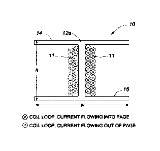
FIG. 2 illustrates an exemplary embodiment. A transducer 10 has a solenoidal
coil 11 of
electrically insulated wire wrapped around the core 12a. Here and elsewhere in
the drawings, a
circle with a cross indicates a cross section of a coil loop wherein a current
flows into the plane
of the drawing, while a double circle indicates a cross section of a coil loop
wherein the current
flows out of the plane of the drawing. The insulation of the wire allows a
magnetic field to pass
therethrough. The two ends of the coil are electrically coupled to two
terminals of a signal
generator (not shown), so that the alternating current can flow through the
coil 11 from the
signal generator and back to the signal generator. In operation an alternating
electrical current in
the form of a 2.5 kHz sine wave is provided to the coil 11. The root mean
square (mis) of the
alternating current amplitude is 133 micro amps. As is well understood, a
magnetic field is
generated emanating from and external to the coil 11. The transducer 10 has a
core 12a made of
a ferromagnetic material, for example, mild steel or stainless steel. Integral
with the core are
planar end pieces 14 and 16, also made of mild steel or stainless steel or
other alloys, with the
relative permeability of from 100 to 5000 and possibly more. The height of the
core 12a is h =
3.5 cm, and the diameter (max dimension) of the end pieces is W = 5 cm.
FIG. 3 illustrates the magnetic lines of flux 32, which are substantially
parallel due to the
elongate, substantially straight shape of the core and due to the field-
shaping effect of the end
pieces 14 and 16 extending nomially to the core. Unconstrained, the core 12a
absent the polar
end pieces, the magnetic lines of flux 34 are not parallel as is shown in FIG.
1. To achieve a
greater effect on the liquid that the transducer is placed in, it is preferred
to have substantially
parallel lines of flux. The end caps 14 and 16, on the poles of the core 12a
of the transducer 10
(FIGs. 2 and 3) concentrate the magnetic lines of flux 32 so that the lines of
flux external to the
coil 11 and core 12a are almost parallel.
Turning now to FIG. 4, the transducer 10 is shown to have a height h and
radius R1. Radius R2
defines the radius from the center of the metal core 12a to the outside of the
coil 11 having N
turns. By way of example, the height of the coil L = 3 cm, h = 3.5 cm, R1 =
2.5 cm, R2 = 0.8
cm, N = 44 turns of 22 gauge single strand insulated wire. The core was made
of mild steel.
Experiments have been performed with said transducer so as to observe the
impact of
exposure of water to magnetic fields as described herein, on mass transfer
rate across the air
7
Date Recue/Date Received 2021-05-05
Our Ref: 318-22 CA
water interface of bubbles. Several frequency and current pairs have been
found to provide
better results than others, in particular, in achieving noticeable change a
property of a polar
liquid at a distance of at least 10 meters: 2500 Hz at the current of 0.100
mA, 2700 Hz at the
current of 0.099 mA, and 4000 Hz at the current of 0.140 mA. The search for
preferable
parameters was based on theoretical hypotheses of how the technology worked,
and included
adjusting parameters while the effect has been measured. More such parameters
may be found
by experimentation. It is expected that the advantageous effect, though
possibly slightly
reduced, may be achieved for frequency and current deviating from the
particular preferable
parameters by 10 Hz and 15 micro Amperes, respectively. The same parameters
may be
advantageously used with other transducers. It should be appreciated that the
parameters of
the magnetic field and the required electrical signal may vary depending on
the liquid, e.g. the
level and nature of contamination in water. The geometry of the vessel or
water body may
also affect the parameters needed to achieve the desired effect.
For the embodiment shown in FIGs. 2 through 4, we have demonstrated that
preventing a
portion of the magnetic field interior to the coil 11 from contacting the
fluid, the other portion
of the magnetic field, the portion exterior to the coil 11, is able to
noticeably and effectively
change a property of the liquid it is submerged in. Thus either blocking the
inside magnetic
field or preventing the liquid from accessing the magnetic field within the
interior of the coil
allows the field exterior to the coil 11 to significantly change a property of
the liquid. The
suggested transducer design ensures that magnetic fields in these different
regions do not
simultaneously pass through the polar liquid or they would have a deleterious
effect on each
other not producing a desired change in a property of the polar liquid.
Preferably the
magnetic field interior to the coil of FIG. 2 is totally or substantially
prevented from
propagating through the liquid; in a less preferred embodiment at least 75% of
the magnetic
field interior to the coil 11 is prevented from penetrating the polar liquid.
Relative to the
portion of the magnetic field exterior to the coil, it is desirable that at
least 10%, preferably
50%, and more preferably 75% of the magnetic field external to the coil, i.e.
excluding the
space occupied by the coil itself and its interior, and emanating from the
coil, penetrate the
liquid. We have discovered that water entering the interior of the coil has a
deleterious effect,
and that completely blocking water from being affected by the magnetic field
within the
8
Date Recue/Date Received 2020-10-30
Our Ref: 318-22 CA
interior of the coil gave us excellent and surprising results. We believe that
the opening
(interior) of the coil should be blocked by at least 65%, better still by 80%,
and ideally 100%.
FIGs. 2 through 4 show embodiments where a property such as interfacial mass
transfer rate
or other properties of the polar liquid can be changed if the transducer is
provided with an
alternating signal of about 2.5 kHz and having a current of about 133
microamperes. Of
course, the embodiments are not limited to this frequency or current, as these
are just
exemplary values that provided surprisingly favorable results. We believe that
frequencies
between 100 Hz and 20 kHz will produce a change in a property of a polar
liquid, with a
preferable interval of frequencies between 1 kHz and 5 kHz.
The aforedescribed transducers may be used in a system for changing a property
of a polar
liquid with a magnetic field. With reference to FIG. 5, the system includes a
signal generator
910 for generating an alternating electrical signal, and at least one
transducer 920, which has an
electrically conductive coil 930 with an insulation which electrically
insulates one loop of the
coil from one another, though allows a magnetic field to pass through. No
electrical current is
imparted from the device to the polar fluid.
The coil 930 is coupled to the signal generator 910, so that the generator 910
can provide an
alternating electrical current to the coil 930, and so providing magnetic
field about the coil 930.
Preferably, the coil 930 is a solenoidal coil, i.e. a cylinder in the sense
that it has a straight
central axis and all cross sections normal to the axis have a same shape,
though not necessarily
a circle. By way of example, the core 12a (FIG. 3) may be a steel bar with a
square cross-
section. The wire wound around such a core forms a cylinder wherein a cross
section resembles
a square with rounded corners. The height of the cylinder may be in the range
of from 3 cm to
50 cm, though coils longer than 10 meters may also be used in other
applications.
The coil is formed of loops of a conductive metal, such as a copper wire, and
is electrically
isolated, e.g. covered with a jacket. The wire is shaped as a coil, possibly
wrapped around a
straight support, thus forming multiple loops. The number of loops may be in
the range of from
20 to 2000 and exceed 5000 in some applications. Each loop has an interior,
and a stack of loop
interiors forms an interior 960 of the coil 930, wherein a support or core may
be disposed.
9
Date Recue/Date Received 2020-10-30
Our Ref: 318-22 CA
The coil interior 960 is protected from the liquid when the transducer is
immersed therein so
that a portion of the magnetic field internal to the coil 930 is substantially
prevented from
penetrating the liquid. The interior 960 of the coil 930 may be filled with
some material as
discussed elsewhere herein, or sealed. While FIG. 5 shows the coil 930 as
having a single layer
of wire, the coil 930 may be formed of one, two, or more layers of wire, a
next layer looped
around a previous layer. FIG. 2 illustrates an embodiment of the transducer
described with
reference to FIG. 5, wherein the coil 11 has two layers of wire.
The transducer 920 has two end pieces 940 and 950 for shaping a portion of the
magnetic field
external to the coil 930 thereby causing it to penetrate the liquid. The end
pieces 940 and 950
are disposed at the ends of the coil 930 transverse thereto, preferably
nottnally, so that the force
lines of the magnetic field between the end pieces are substantially parallel
to the central axis of
the coil 930. The end pieces 940 and 950 are electrically isolated from the
coil. Each of the end
pieces 940 and 950 is made of one or more magnetically pettneable materials
with relative
pettneability of at least 100 times higher than relative pettneability of the
polar liquid under the
treatment, preferably of a ferromagnetic material such as mild steel or
stainless steel or other
alloys, with the relative penneability of from 100 to 5000 and possibly more.
The end pieces
may be coated with a suitable material to prevent corrosion. The end pieces
940 and 950 may be
planar and normal to the coil. They may be round and centered at the coil. The
diameters (max
measurement) of the end pieces are preferably at least half of the height of
the coil which, in
turn, may be 3 cm < L < 50 cm
The interior 960 of the coil 930 may be filled with any material or sealed so
as to ensure that the
liquid is substantially prevented from entering the interior of the coil and,
thus, is not affected
by a portion of the magnetic field within the interior of the coil. Ideally
100% of liquid is
prevented from entering the interior of the coil. Less preferably, 80% and
less preferably 65% is
prevented. In other words, preferably the entire interior of the coil is not
accessible by the polar
liquid and, less preferably, at least 80% of the coil interior is not
accessible by the polar liquid.
Ideally, the interior of the coil is totally blocked so as to prevent the
polar liquid accessing the
coil interior. In one embodiment, the interior 960 of the coil is filled with
one or more non-
ferromagnetic materials, i.e. materials with relative magnetic petmeability
less than or equal to
1 11/m. The core may be coated with a suitable material to prevent corrosion
in the liquid.
Date Recue/Date Received 2020-10-30
Our Ref: 318-22 CA
In one embodiment, the interior 960 of the coil 930 is sealed e.g. by placing
the coil into a
container which allows the magnetic field to pass therethrough, so that the
interior 960 is not
accessible by the liquid when the transducer 920 is at least partially
immersed thereto. The end
pieces 940 and 950 may be outside of the container so that the liquid can be
affected by a
portion of the magnetic field between the end pieces. In one embodiment, the
coil interior is
only partially sealed, while the opening is not in contact with the liquid,
e.g. the transducer 920
is disposed at the surface of the liquid.
In one embodiment, the interior of the coil is filled with air or another gas,
or a mixture of
gases, which may support the device at the surface of the liquid. In another
embodiment the
interior of the coil is under a vacuum and is properly sealed.
In one embodiment, the interior 960 of the coil 930 may contain a straight
core fonned of a
material suitable for the end pieces 940 and 950, preferably a ferromagnetic
material for
increasing the magnetic flux density produced by the coil. The end pieces 940
and 950 may be
coupled to the core, or integral therewith as illustrated in FIG. 2 wherein
the transducer 10 is an
embodiment of the transducer 920. However, it is not necessary for the end
pieces 940 and 950
to contact the core, though they should be disposed at the ends of the coil,
in close proximity
thereto and, preferably, in contact with the core. In one embodiment, the core
and the end pieces
are electrically isolated from the liquid.
In an embodiment illustrated in FIG. 7, surfaces 14a and 16a of the end pieces
14' and 16' may
be referred to as internal surfaces, in the sense that each of them faces
another end piece. The
internal surfaces 14a and 16a are sloped or curved so that they are farther
from one another at
the coil and closer to one another away from the coil. The purpose of such an
arrangement is to
shape a portion of the magnetic field external to the coil, so as to expand
the spatial portion 35
(FIG. 1) around the coil 11, where the field lines 34 are substantially
parallel each other.
In one embodiment, the solenoidal coil is sealed within a water-tight
container 340 (FIG. 7)
fitting close along the coil and extending significantly beyond the ends of
the coil, by at least 1
or 5%, preferably by 10 % and, more preferably, by at least 20% of a height of
the coil, so as to
prevent the liquid from entering the interior of the coil and the polar
portions of the magnetic
field. In yet another embodiment, the coil has a non-magnetic core 350
extending significantly
11
Date Recue/Date Received 2020-10-30
Our Ref: 318-22 CA
beyond the ends of the coil, by at least 1 or 5%, preferably by 10 % and, more
preferably, by at
least 20 % of a height of the coil, for the same purpose. Of course, the
transducer may be only
partially immersed in the polar liquid. The last two embodiments may include
end pieces as
described in this disclosure.
The signal generator 910 (FIG. 5) may be configured for providing a periodic
electrical current
with a predetettnined amplitude and frequency. The current is preferably less
than 3 amperes,
more preferably less than 500 mA, and more preferably less than 50 mA. A
feedback loop may
be used to control the electrical signal in dependence upon a measured
parameter, which may
be, but not limited to, a value of gas exchange rate, surface tension,
viscosity, freezing point
temperature, or partial vapor pressure. The signal generator 910 may be
capable of providing a
plurality of predetettnined frequencies or a predefined range of frequencies,
and the system may
utilize a frequency detettnined to be optimum from the plurality of
frequencies. A measuring
instrument capable of measuring a parameter, such as a value of gas exchange
rate, surface
tension, viscosity, freezing point temperature, or partial vapor pressure, can
be connected to a
feedback circuit that can be used to adjust the frequency and amplitude of the
signal provided to
the transducer to optimize or enhance a process that requires a change in
property of the polar
liquid.
In particular, the signal generator 910 may be configured to work in at least
one of the
following modes experimentally found to provide advantageous results: 2500 Hz
at the current
of 0.100 mA, 2700 Hz at the current of 0.099 mA, and 4000 Hz at the current of
0.140 mA. It
is expected that almost the advantageous effect may be achieved for frequency
and current
deviating from the particular optimal parameters by +/- 10 Hz and +/- 15 uA,
respectively,
while the effect may be reduced to about 63% of the peak effectiveness.
The transducer 920 and the signal generator 910 may be part of an ALPIM device
970 intended
to be at least partially immersed in an industrial pond, river, ocean, etc.
Preferably, the signal
generator and the transducer are housed separately and connected by a pair of
wires or a coaxial
cable. In one embodiment, the coil is at least partially immersed in the
liquid, while the signal
generator is not immersed ¨ it may reside on a raft whereto the coil is
attached. In another
embodiment, the signal generator is at least partially immersed in the liquid.
Then the interior of
12
Date Recue/Date Received 2020-10-30
Our Ref: 318-22 CA
PPH
the transducer 920 provides an electrically isolated space in which to house
the electronics
required to operate the device. In one embodiment, the ALPIM device includes
floating means,
such as foam flotation ballast. In one embodiment flotation is provided by
trapping air or foam
.. in the sealed container wherein the electronics are kept. Foam helps to
avoid the diurnal
expansion and contraction of the air with the accompanying condensation of
moisture inside the
electronic housing. A metallic strip through the foam may be used to permit
the transmission of
heat generated by the electronic circuit. The ALPIM device 970 may have an
antenna for
wireless communication with a control center or other transducers, and/or a
GPS receiver. A
person skilled in the art would appreciate that features of different
embodiments may be
combined if they are not mutually exclusive.
In operation, one or more transducers may be used for providing a magnetic
field to a polar
liquid so as to change a property thereof. With reference to FIG. 8, the
method includes the
following steps: (A) disposing a first transducer at least partially within
the polar liquid,
.. wherein the transducer includes a first electrically conductive solenoidal
coil formed of a
plurality of loops each having an interior, the loop interiors forming an
interior of the coil,
wherein the interior of the coil is filled, sealed, or opens out of the liquid
so as to prevent the
polar liquid from outside the coil from penetrating the interior of the coil,
and (B) applying a
first alternating electrical current to the coil so as to produce a first
magnetic field about the
coil, the field having a portion internal to the coil and a portion external
to the coil, the
external portion penetrating the polar liquid. The first alternating
electrical current has a first
frequency and a first amplitude such that the external portion of the first
magnetic field has an
effect on the polar liquid thereby changing the property of the polar liquid
at a distance of at
least 5 meters from the first transducer, preferably 10 meters from the first
transducer, and
more preferably, the distance is at least 40 meters, and even more preferably
the distance is at
least 150 meters. We believe that the effect produced by the magnetic field is
the domino
effect discussed above. Preferably, the transducer produces no electric field
outside thereof
greater than 1 V/m. Even a very small electric field that may be produced by
the coil is
unwanted. FIG. 8 illustrates a flowchart of the method, wherein method steps
810 and 820
may be performed in any order, including concurrent execution.
13
Date Recue/Date Received 2021-05-05
Our Ref: 318-22 CA
The property of the polar liquid is an intrinsic property, such as viscosity,
surface tension,
equilibrium partial pressure in the gas phase of the polar liquid, maximum
dissolved gas
saturation concentration for a particular gas, heat of vaporization, a
freezing point, or a boiling
point of the polar liquid. The advantages of the method have been demonstrated
for such
properties as gas exchange rate through the interfacial film at the surface of
the liquid and that
of gas bubbles in the liquid. The inventors believe that other properties of a
polar liquid may
be controlled using magnetic field as described herein. The value of the
change in a particular
property of the liquid depends on the nature of the property and physical
mechanisms
involved. In particular, at the distance of 5 meters from the transducer, the
gas exchange rate
of the polar liquid changes by at least 5 %, the surface tension of the polar
liquid changes by
at least 1 %, the viscosity of the polar liquid changes by at least 0.5 %, the
freezing point
temperature of the polar liquid changes by at least 0.1 degree C, or the
partial vapor pressure
of the polar liquid changes by at least 1%.
The time necessary for the change to become detectable depends on the distance
from the
transducer. In our experiments, changes in an interfacial mass transfer rate
were noticeable
after 2 min at 10 meters, were unmistakable after 6 min, and continued to grow
after 96 hrs.
The impact was also measureable at 150 m within 24 hrs. In general, a property
of the polar
liquid changes at the distance of 5 meters within 10 minutes.
The alternating electrical current may have a sinusoidal profile, a
trapezoidal profile, a
triangular profile, etc. The frequency and amplitude of the electrical current
used in the
transducer depend on the particular liquid and, possibly, on the property
desired to be
changed. Our experiments show that some frequencies produce the change greater
and/or
faster than other frequencies. The found parameters are provided herein. When
such
parameters are not known, the system may be configured to perfottn a sweep
through a range
of frequencies, staying at a particular frequency for a predetermined interval
of time, while
the property of the liquid is monitored. In general, the frequency of the
electrical current used
to energize the transducer is greater than 100 Hz and less than 5000 Hz, and a
root mean
square of the amplitude is less than 3 amperes, preferably less than 500 mA,
and more
preferably less than 50 mA.
14
Date Recue/Date Received 2020-10-30
Our Ref: 318-22 CA
It should be understood that the method disclosed herein is practicable by
simply using a coil
having a plurality of turns without having a core 12a, when the interior of
the coil is empty
but inaccessible to the liquid, e.g. sealed. In another embodiment, a
magnetically permeable
core is provided. Alternatively, the core can be a plastic spool for example
used to foun the
.. many turns of wire resulting in the coil. The spool may be another
material, which does not
deleteriously affect the transducer's performance, or there may be no spool or
core present
and the liquid may be prevented from entering the interior of the coil by
other means.
FIGs. 2 through 4 illustrate transducers whereby a property such as an
interfacial mass
transfer rate or other properties of a polar liquid can be changed if the
transducer is provided
with an alternating signal e.g. of about 2.5 kHz and having a current of about
133
microamperes. Of course, the method is not limited to this frequency or
current, as these are
just exemplary embodiments that provided surprisingly favourable results. We
believe that
frequencies between 100 Hz and 20 kHz will produce a change in a property of a
polar liquid,
with a preferable interval of frequencies between 1 kHz and 5 kHz.
With reference to Fig. 6, the aforedescribed transducers may be used in a
multi-transducer
system 200. The system includes at least two transducers 210 and 230 and a
control center
250. Each of the transducers includes a coil for generating magnetic field
when provided with
an alternating electrical current. Preferably, the transducers are cylindrical
coils and include
end pieces as described above. However, other transducers may be used under
control of the
control center 250. Preferably, each of the transducers is electrically
connected to its own
signal generator. As shown in FIG. 6, a first signal generator 220 provides an
alternating
electrical current to the first transducer 210, and a second signal generator
240 ¨ to the second
transducer 230. In another embodiment, one signal generator provides an
electrical current to
two or more transducers.
Turning back to FIG. 6, the transducers may be placed in a vessel or an open
body of water or
sludge, etc., 260. By way of example, ALPIM devices 201 and 202, each
incorporating a
transducer and preferably a signal generator, may be paced at a distance D (20
cm < D < 300
m) from one another at least partially immersed in an industrial pond, river,
lake or ocean.
The control center 250 may be located ashore or elsewhere and communicate with
the devices
Date Recue/Date Received 2020-10-30
Our Ref: 318-22 CA
201 and 202 over any communication protocol, preferably wirelessly. In one
embodiment,
multiple transducers may be deployed without a controller.
We have discovered that by placing two transducers, for example, two coil
transducers, within
a polar liquid or body of water, different effects can be obtained depending
upon how the two
.. transducers are operated. This provides a convenient way, in which a
desired property of the
polar liquid may be controlled, such as viscosity, surface tension,
equilibrium partial pressure
in the gas phase, maximum dissolved gas saturation concentrations, heat of
vaporization, and
freezing or boiling point of the polar liquid.
Two or more transducers may be used together and controlled from a same
control center,
wherein frequencies of the electrical current in the transducers are same and
the first and
second alternating electrical currents are in phase, having a zero degree
phase relationship for
increasing the change in the polar liquid. We have discovered that by using
two transducers
10 provided with a same frequency alternating signal and wherein the signals
are in phase,
interfacial mass transfer rate was increased further than the increase
provided by a single
transducer. By way of example, a 16% increase in interfacial mass transfer
rate provided by a
single transducer was further increased to 20% when a second transducer having
the same
frequency and in phase was introduced; the transducers should be spaced apart
a suitable
distance to maximize a desired effect. For example, a plurality of transducers
can be spaced
along a water body such as a channel in order to change the freezing
temperature of the water
.. in the regions of the channel about which the transducers are placed.
Adjusting the phase
between the two signals provided to two transducers so that the two signals
were out of phase,
that is, offset or skewed in phase by varying amounts attenuated the desired
effect. The
property change lessened down to close to or about zero, in this instance the
transducers
having little or no effect. Notwithstanding, since skewing the phase
attenuated the desired
effect, tuning in manner by adjusting the phase by small offsets (gradually)
is a way in which
control of the desired effect can be achieved. For example a 20% increase in
interfacial mass
transfer rate achieved with two transducers having signals in phase, could be
lessened for
example to 10% by skewing the phase accordingly. In one embodiment, the system
includes
two and more transducers and means for providing a gradual change in a
difference between
the frequency of a current provided to a first transducer and the frequency of
a current
16
Date Recue/Date Received 2020-10-30
Our Ref: 318-22 CA
provided to a second transducer, for controlling the effect induced in the
polar liquid by the
magnetic field of the transducers. The phase change means may be implemented
in a circuit
and/or software, and may be disposed in a control center.
Furthermore, two or more transducers may be used together and controlled from
a same
.. control center, wherein frequencies of the electrical current in the
transducers differ from one
another, for changing the property of the polar liquid oppositely to the
change caused by one
transducer alone. The opposite changes are understood as opposite with respect
to a baseline
of the property when the liquid has not been treated by a magnetic field. The
baseline is the
natural state of the liquid before the transducer(s) are turned on and affect
the liquid in any
manner. By way of example, one transducer may increase a particular parameter
measuring a
property of the liquid above the baseline characterizing the untreated liquid,
while two
transducers with offset frequencies will decrease the same parameter below the
baseline.
We have discovered that a difference in frequency between two transducers by
even 1 Hz
changed the effect on the polar liquid, decreasing interfacial mass transfer
rate below that of
untreated polar liquid rather than increasing interfacial mass transfer rate.
Interfacial mass
transfer rate is one of many properties that can be changed. The same effect
was found with a
5 Hz offset in frequency. If we offset the phase gradually, the effect is
attenuated more and
more all the way down to zero. This is important as it allows us to control
the intensity of the
effect.
Advantageously, the system disclosed herein can be placed within any liquid
that will
accommodate it. It can be scaled up, or down in size as required. Different
industrial
applications may dictate different depth of placement of our device. In most
open water
bodies the remediation effort is driven by the oxygen transfer on the surface
of the water
body. Placing one or more transducers near the water surface with a floating
device to
accommodate a fluctuating water level is the preferred embodiment. In contrast
prior art
systems which require being external to a pipe or conduit in which water
flows, requires a
pipe that will allow a magnetic field to penetrate and flow through without
significantly
affecting the field. Furtheimore, such systems cannot easily be moved from one
location to
another. Once fixed to a pipe it typically remains in place.
17
Date Recue/Date Received 2020-10-30
Our Ref: 318-22 CA
A method for separating a polar and non-polar liquid in an emulsion hereof may
include:
introducing the emulsion into a mixing chamber and placing a first transducer
and a second
transducer in contact with the polar/non-polar emulsion; applying a selected
signal at a chosen
amplitude and frequency to the first transducer and a selected signal which is
at least 1 Hz
different than that for the first transducer to the second transducer such
that the transducers
provide two slightly misaligned-frequency signals and magnetic fields to the
emulsion for
producing a change in water surface tension. The resulting corresponding
higher oil/water
interfacial tension will favor the coalescence of colliding non-polar liquid
droplets in the polar
and non-polar liquids under mild mixing conditions. The mild mixing conditions
may be
generated by a mechanical mixer in a vessel equipped with mechanical buffers
or a section of
piping equipped with a mixing valve to generate a chamber/piping Reynolds
Number of 5 ¨
50. It is desirable to generate a chamber/piping Reynolds Number of 10 ¨ 30 in
accordance
with the inverse of the concentration of the non-polar liquid in the polar
liquid. The chamber
Reynolds Number should be adjusted higher for a lower concentration of non-
polar liquid in
the polar liquid. The chamber Reynolds Number should be adjusted lower for a
higher
concentration of non-polar liquids in a polar liquid. The same set of
principles would apply
for a polar liquid in a non-polar liquid. Preferably, the residence time in
the mixing chamber
is 1 ¨ 30 minutes. The residence time is defined as the effective Chamber
volume over the
emulsion flow rate. The above descriptions are two of many mechanical
arrangements which
may be employed to achieve the specific mixing conditions specified herein.
The mixed
emulsion exiting the mixing chamber enters a conventional industrial separator
for polar/non-
polar emulsions for the next stage of processing to achieve the targeted
accelerated separation
of the polar and non-polar liquids.
In operation, the transducer may be at least partially submerged in a polar
liquid that is used
in the manufacturing of a product or for washing a product. The application of
the alternating
electrical current may lessen the drying time of the product. In another
embodiment, the polar
liquid is an emulsion and the application of the alternating electrical
current assists in
separating at least a portion of the emulsion.
The transducer described heretofore or a plurality of such transducers, spaced
apart and in
various modes of operation, may be used for altering water conditions in a
water body by
18
Date Recue/Date Received 2020-10-30
Our Ref: 318-22 CA
increasing levels of dissolved oxygen and increasing oxidation-reduction
potential (ORP) in
the presence of a low intensity magnetic field to favour the growth of aerobic
bacteria and
added diatoms as a means of suppressing residual ammonia concentration and the
growth of
cyanobacteria and the like.
.. The overabundance of cyanobacteria in stagnant waters, as a result of the
eutrophication of
water, is a worldwide problem, especially because of the fact that vegetative
secretions of
cyanobacteria can be toxic.
Currently, cyanobacteria in stagnant waters of lakes and dams are disposed of
by means of
biomechanical equipment using float structures, built on the principles of
biological reduction
of phosphorus and nitrogen in water by cultivating special aquatic plants. The
disadvantages
of these devices are low efficiency, requirement of taking care of plant
growth and limitations
due to the vegetation period of plants.
Accordingly, the disclosure provides a viable, cost effective system and
method for
significantly reducing the presence of residual ammonia, and cyanobacteria
commonly known
as blue-green algae, from large bodies of water where it is present. Seeding
bodies of water
with diatoms had been found to lessen the presence of blue-green algal blooms
or red-tide
algal blooms. However this treatment alone has not been found to be always
reliable and
effective enough.
A method in accordance with this disclosure is provided for lessening the
presence of residual
ammonia and/or blue-green algae comprising: seeding a body of water with a
population of
diatoms; adding small amounts of nitrates and micronutrients if warranted by
the chemical
make-up of the water body, and, changing an aspect of the body of water by
submerging a
transducer into the water and providing a magnetic field within the body of
water so that the
diatoms and the nitrification bacteria in the water are "activated" in the
presence of a high
ORP and more dissolved oxygen than would otherwise be present in the absence
of the
provided magnetic field.
A surprising unexpected aspect of the method disclosed herein is that a very
low intensity
alternating electrical signal can affect the amount of dissolved oxygen, ORP
(oxidation
19
Date Recue/Date Received 2020-10-30
Our Ref: 318-22 CA
reduction potential) and other physicochemical properties of the water and as
a result the
growth of diatoms and nitrification bacteria at least 5 meters, and more
preferably 50 meters
from the source of the signal. We believe this effect is a function of the
domino phenomenon
described heretofore, whereby certain properties of water molecules subjected
to a magnetic
field are changed, affecting other nearby molecules and this repeated for
considerable
distance.
A diatom is a single-celled alga that has a cell wall of silica. Diatoms can
assimilate both
ammonia and nitrates in their growth. Unlike cyanobacteria, which do not have
an internal
membrane, nitrates can migrate through the cell membrane of diatoms and be
reduced to
ammonia inside the diatoms before being converted into amino acids for the
growth of the
diatoms and their reproduction through cell splitting. On the other hand, the
presence of
ammonium ions in the water is necessary for the gemiination of spores and
heterocysts of
cyanobacteria. The competition for the ammonia in the water by blue-green
algae and
diatoms may also be influenced by the nitrogen-phosphorous (N:P) ratio in the
water.
Published studies have shown the competitive uptake of ammonia and nitrates by
diatoms,
cyanobacteria (blue-green algae) and chlorophylls (green algae). Diatoms,
especially the
species consisting of combinations of Cyclotella meneghiniana, Synedra ulna
and various
species of Nitzschia have high rates of uptake of nitrates when biological
oxygen demand
(BOD) exceeds 5 ppm.
Under the high dissolved oxygen and ORP (+50 to +350 mV) environment generated
by the
transducer(s), most ammonium ions are oxidized to nitrates by the aerobic
nitrification
bacteria present in the water body. However, when there is a heavy presence of
organic
sludge, it competes for the dissolved oxygen in the water as demonstrated by
the repeated
decline of dissolved oxygen to near zero in water bodies during the night. The
presence of
ammonium ions in the water bodies will likely persist until the sludge-induced
competitive
demand for dissolved oxygen begins to decline. Consequently, the continuing
presence of
blue-green algae will also persist until there is sufficient dissolved oxygen
and/or diatoms in
the water to eliminate any significant presence of ammonia and/or phosphates
in the water.
Date Recue/Date Received 2020-10-30
Our Ref: 318-22 CA
Seeding the water body with diatoms alone will not be effective in
consistently suppressing
the growth of blue-green algae.
However seeding the water body with diatoms and subjecting the water body to a
magnetic
field by submersing a transducer within the water body can lessen the amount
of blue-green
algae in that body of water, over time.
In order to affect a water body that is to be treated, the magnetic field must
be able to
penetrate the water under treatment at some point, from which point the domino
effect travels
through the water body beyond the immediate vicinity of the transducer that
introduced the
magnetic field to the water. This can be achieved by generating a current
dependent upon a
signal produced by a signal generator. A sine wave having a predeteimined
frequency and
amplitude is used to generate a desired signal for providing a desired current
to an effector or
transducer which results in a magnetic field being generated about and
external to the
transducer emanating from the transducer. Providing a transducer that is
submerged in the
liquid to be affected has numerous advantages. For example, a properly sized
transducer of
this type energized by an alternating signal can be used to alter a property
of water in a lake, a
pond, sewage lagoon, water reservoir, stomi water pond and similar water
bodies, a container
or a pipe by being introduced directly into the liquid sample to be treated.
Furthemiore, a
transducer of this type operates at very low power in the milliwatts range to
have far reaching
effects. We have discovered that a properly sized transducer in accordance
with this
disclosure is able to affect the amount of dissolved oxygen in water tens of
meters from where
the transducer is placed over time. With a transducer we used, in one instance
surprisingly a
signal of approximately about 133 microamperes, at a frequency of about 2.5
kHz was able to
generate an effect that was measurable over 40 meters away from the point of
treatment in
open water.
The method disclosed herein may include exposing seeded diatoms within a large
body of
water to a low power alternating magnetic signal using the transducer
described. Depending
on the residual ammonia concentration and the extent of presence of blue-green
algae in the
water body, the effective live diatoms concentration in the water body should
be in the range
of 100 ¨ 10,000 medial counts per milliliter (m1). Subject to cost
effectiveness considerations,
21
Date Recue/Date Received 2020-10-30
Our Ref: 318-22 CA
PPH
the preferred live diatoms concentration would be 1,000 ¨ 5,000 medial counts
per ml.
Nurturing a live diatoms concentration above 10,000 medial counts per ml may
be preferable
for water bodies requiring extensive and accelerated treatments. The high
dissolved oxygen
and the growing presence of the diatoms will foster a growing population of
fish. The growth
of the diatoms and its consumption by the fish will restore a balanced ecology
for the water
body. Live diatoms with nitrates and/or micronutrients may be sourced from
commercial
suppliers, such as Lake Savers, Nualgi Ponds, etc.
The body of water can be pretreated by first providing the low power signal to
the water well
in advance of seeding, and continuing to provide the signal for a duration of
time after seeding
takes place.
Alternatively, if there is an absence of fish in the water body and the
dissolved oxygen
concentration is below 3 milligram per litre (mg/1), the body of water is
preferably first treated
by a transducer energized with a low power signal as described above, until
the dissolved
oxygen level is consistently above 3 mg/1 before added live diatoms are
introduced. With the
continuing application of the low power signal, the preferred dissolved oxygen
level should
be consistently above 5 mg/1 and the ORP consistently above +150 mV. After the
seeding of
live diatoms and when the live diatoms concentration is at least 1,000 and
preferably 5,000
medial counts per ml or higher, native fish may be introduced into the water
body to maintain
an ecological balance.
In another embodiment, the dissolved oxygen in the water body may be 5 mg/l.
The
transducer with the low power signal should still be deployed shortly before
or after the
seeding of live diatoms into the water body to maintain an ORP consistently
above +150 mV
and to "activate" the live diatoms and the nitrification bacteria.
In a waste water lagoon where there is a continuing input of nutrients, the
application of the
transducer with the low power signal may be continued to maintain a high
dissolved oxygen
level above 3 mg/1, an ORP above +150 mV and a live diatoms concentration
above 1,000
medial counts per ml.
22
Date Recue/Date Received 2021-05-05
Our Ref: 318-22 CA
If during the treatment process, the live diatoms concentration should fall
below 1,000 medial
counts per ml, another seeding of live diatoms into the water body may be
undertaken with
the objective of consistently maintaining a live diatoms concentration of
2,000 to 5,000
medial counts per ml in the water until the targeted residual ammonia
concentration and the
desired control of blue-green algae have been accomplished.
In another embodiment, if the live diatoms concentration of the targeted water
body is above
5,000 medial counts per ml, applying the low power signal alone without
further live diatoms
seeding may be adequate to achieve the targeted residual ammonia concentration
and control
of the blue-green algae.
If the targeted water body is covered by a solid sheet of ice, the deployment
of the low power
signal may be accompanied by an underwater air diffuser to provide an adequate
source of
oxygen to raise the dissolved oxygen level and the associated ORP in the water
to the
preferred dissolved oxygen levels above 5 mg/1 and the ORP above +150 mV.
In accordance with the present disclosure, a robust living aquatic environment
may be
maintained by using an alternating magnetic signal in a body of water to
generate high
dissolved oxygen and ORP across a large water surface in combination with the
simultaneous
seeding of diatoms and the addition of small amount of nitrates and
micronutrients, if
warranted, to promote the growth of the diatoms and to suppress the
gelmination of spores of
blue-green algae. A simultaneously healthy native fish population will help
maintain the
desirable ecological balance of the water body.
In summary, we have found that by providing one or more properly designed
transducers we
are able to affect physicochemical properties of water at least 150 meters
away from where
the effector is placed and submerged in a large body of water irrespective of
the conductivity
of the water. Furtheimore, this can be done using a very low power signal that
can be
energized from a solar panel with accompanying battery for energy storage. We
believe that
doing this in combination with seeding a body of water with diatoms and, if
warranted, small
amount of nitrates, micronutrients and a population of fish native to the
area, may have a
profound effect and can significantly lessen the presence of residual ammonia
and
cyanobacteria present in a lake, pond, stream or lagoon.
23
Date Recue/Date Received 2020-10-30
Our Ref: 318-22 CA
In one embodiment, the transducer and signal generator described heretofore is
used to
separate different constituents in an emulsion where one is a polar liquid.
Oil-in-water is one
of many emulsions that this disclosure relates to. Generally, however, this
disclosure relates to
separation of a polar and non-polar liquid, which form an emulsion.
Removal of oil from oil-in-water emulsions is an important process in oil
fields and refineries.
When compared to methods, such as chemical de-emulsification, gravity or
centrifugal
settling, pH adjustment, filtration, heat treatment, membrane separation, and
the like, methods
using electric fields have been considered attractive because they have the
potential for
increasing throughput, saving space, and reducing operating costs for many
water-removal
applications. The use of electric fields for separating water from water-oil
mixtures of crude
oil was first demonstrated in 1911, and numerous studies have been conducted
more than a
century for optimizing the process and expanding on the original idea.
Separation of oil from
water is known using magnetic fields whereby particulate matter having
magnetic properties
is added to the emulsion, binds to the oil, and a magnet is used to pull these
along with oil
from the water. Although some of these electrical/magnetic ideas may have some
benefit,
very few of them have been demonstrated to be cost effective for
commercialization. There is
significant room for improvement in the field of separation of emulsion
constituents.
In one embodiment, two transducers separated by a distance of approximately 1
meter
between them are fixed on the mixing chamber inside wall opposite from the
inlet port of the
chamber at or about 10 cm from the bottom of the mixing chamber.
In one embodiment, one or more transducers with aligned frequencies, phase,
amplitudes may
be fixed in a conventional separator chamber on the inside wall near the inlet
port of the
separator chamber, such as a dissolved or dispersed air flotation unit, to
allow the magnetic
field to change the physicochemical properties, such as, a reduction of the
viscosity of the
polar liquid to achieve higher settling/rising velocity of the non-polar
coalesced droplets to
achieve accelerated separation.
In the case of the dissolved air flotation unit, the separation is
particularly slow because very
fine air bubbles precipitate out of solution and attach themselves to the non-
polar liquid
24
Date Recue/Date Received 2020-10-30
Our Ref: 318-22 CA
particles, which tend to rise very slowly. The magnetic field affecting
properties of the liquid
as disclosed herein may provide more buoyancy and a speedier ascent of non-
polar particles.
The method disclosed herein may also lower the viscosity of the polar liquid.
This lower
viscosity will peitnit the coalesced non-polar liquid particles and/or the air
bubbles in a
dispersed air flotation unit to ascend faster through the polar liquid and
accelerate the
separation.
In this embodiment, the method will increase the processing capacity of both
the dissolved air
flotation unit and the dispersed air flotation unit.
In another embodiment, a transducer placed inside a pipe elbow near the inlet
port of an API
oil/water separator will impose the specified magnetic field on the emulsion
flowing past the
transducer. The treatment effect may expand and persist in the polar liquid as
the emulsion
flows gently through the plates inside the API oil/water separator. The lower
viscosity of the
magnetically treated polar liquid may encourage more rapid migration of the
non-polar liquid
droplets towards the plates in the API oil/water separator to result in a more
speedy separation
and a higher processing capacity of the separator.
In another embodiment of the method, in the process of separating milk fats
from raw milk
which is an aqueous emulsion of milk fats, a transducer placed inside a pipe
elbow near the
inlet port of a centrifuge may impose the specified magnetic field on the raw
milk flowing
past the transducer. The treatment effect may expand and persist in the polar
liquid as the
milk is subjected to the centrifugal force inside the centrifuge. The lower
viscosity of the
magnetically treated polar liquid may encourage more rapid migration of the
non-polar liquid
droplets (cream) towards the centre of the centrifuge to result in a more
speedy separation and
a higher processing capacity of the separator. Alternatively, this method may
peitnit a lower
rotational speed of the centrifuge with a resulting lower capital cost and
operating cost in the
separation of cream from raw milk.
In order to affect an emulsion that is to be treated, the magnetic field
should be able to
penetrate the polar liquid under treatment at some point, from which point the
effect of
magnetically affected polar molecules migrates through the polar liquid beyond
the immediate
Date Recue/Date Received 2020-10-30
Our Ref: 318-22 CA
vicinity of the transducer that introduced the magnetic field to the emulsion.
Therefore a
change in property such as surface tension reaches a great distance through
this domino effect.
Affected water molecules affect other nearby water molecules and this
surprisingly continues
outward for some distance. This can be achieved by generating a current
dependent upon a
signal produced by a signal generator. A sine wave having a predetelmined
frequency and
amplitude is used to generate a desired signal for providing a desired current
to a transducer
which results in a magnetic field being generated about and external to the
transducer
emanating from the transducer. Providing a transducer that is submerged in the
liquid to be
affected has numerous advantages. Treating an emulsion in a smaller
containment vessel is
practicable.
Another embodiment of this disclosure relates to using the transducer
described heretofore to
lessen the drying time in an industrial process.
The production capacity of a Fourdrinier paper machine is limited by the water
drainage rate
at the Wet End, the rate of flow of the water from the paper sheet to the felt
in the Wet Press
Section and the rate of vaporization of the water in the Drying Section. The
modified
characteristics of the magnetically treated water pennit a much more rapid
drainage of the
water from the pulp slurry which is fed by gravity from the Headbox through a
Slice at or
about a consistency of 0.1 - 0.4% solids onto the rapidly moving (200 -2,500
m/min) wire
mesh of the Fanning Section of the paper machine. The sheet consistency would
be
approximately 25% solids when the sheet exits the Foiming Section and enter
the Wet Press
Section from which the sheet will exit at a consistency of approximately 40-
55% solids. The
paper sheet will exit the subsequent Drying Section with a moisture content of
approximately
2-12%. The higher equilibrium partial pressure and the slightly lower heat of
vaporization of
the magnetically treated water in the sheet may permit a more rapid drying
rate with lower
energy consumption.
In one embodiment, one or more transducers with aligned frequency, phase and
amplitude as
described heretofore, are placed in the White Water wire pit on the walls and
near the exit
port leading to the suction port of a fan pump which circulates the White
Water back to the
Founing Section of the paper machine. One or more transducers with aligned
frequency,
26
Date Recue/Date Received 2020-10-30
Our Ref: 318-22 CA
phase and amplitude are placed near the respective exit ports of the
Whitewater Chest and the
Headbox to provide maximum exposure of the specific magnetic field to the
White Water and
the pulp slurry being circulated at the Forming Section. It is preferable that
all the transducers
are synchronized to produce electrical signals alternating with the same
frequency, phase and
amplitude. It is preferable that the respective frequency, phase and amplitude
of the different
sets of transducers in this process are substantially aligned. Minor
misalignments may
diminish the targeted treatment impacts on the process.
Through operational optimization, the number of transducers may be increased
or decreased
to achieve the most desirable cost effectiveness.
In another embodiment, the transducer may be placed through the piping elbows
in the
Forming Section as a replacement or in addition to the transducer placements
in the tanks. In
one embodiment, if more than one transducer is placed inside a tank, the
transducers are
disposed on opposite walls or corners of the tank.
Depending on the specific configurations of a paper machine, the production
capacity increase
with magnetic field treatment of the white water in the Forming Section and
the paper sheet in
the subsequent processing sections is expected to be approximately 5-30%.
The flow rates of different drying operations span a wide range, from paper
making at the
high end to pharmaceuticals at the low end. The liquid phase may include but
is not limited to
water, alcohols and many different polar and non-polar solvents. The final
product may
include sheets of paper, boards, pulps, plastics, automotive coatings, etc.,
amorphous particles
or powder; grains, corn, diced vegetables; strings, e.g. noodles; etc. All of
these require drying
in their manufacture.
Furthermore, in accordance with the method disclosed herein, multiple
transducers with a
combination of frequency, phase, amplitude and separation distance may be
placed so as to
achieve changes of a property of a polar liquid without the addition of
chemicals.
The polar liquid may form a river, lake, pond, lagoon, or other body of water.
Applying the
alternating electrical current to the transducer may result in an increase in
dissolved oxygen or
other dissolved gasses within the polar liquid. Diatoms may be added to the
polar liquid
27
Date Recue/Date Received 2020-10-30
Our Ref: 318-22 CA
before or concurrently with energizing the transducer, so as to lessen
cyanobacteria, algal
blooms, ammonia, phosphates or total nitrogen in the polar liquid over time.
A polar liquid treated by the transducer(s) may be used for aquaculture, in
particular, for
growing aquatic animals, such as fish or shrimp. Optionally, diatoms, oxygen,
and/or air may
be added to the polar liquid. We believe that the method disclosed herein is
beneficial in fish
and/or shrimp fanning. Typically shrimp fanning is done in large ponds and
these ponds
often need to be dredged after a period of time due to fish/shrimp waste
settling on the bottom
of these ponds.
An aspect of this disclosure relates to fish and shrimp fanning. The
biochemical process of
digesting fish wastes in-situ is not that different from that for human
sewage. Nevertheless,
fish waste is often characterized by the ingredients in the fish feed. Any
undesirable
contaminants in the fish feed, e.g. heavy metals, inorganic chemicals, will
show up in the fish
wastes. Obtaining information related to the inorganic chemicals, including
heavy metals,
chlorides and sulfates, in the fish feed and the fish wastes to ensure that
the in-situ waste
digestion process would not become a pathway for the accumulation of inorganic
chemicals,
especially heavy metals, in the water in the fish pond can be useful.
The assertion that fish would feed on fish waste is scientifically dubious,
especially if fish
feed pellets are available. The observation may be a confusion with the fish
trying to retrieve
fish feed pellets buried under the accumulated fish wastes. Consequently, the
growth of the
fish will be inhibited if a large portion of the fish feed, especially those
in pellet form, is
buried under a thickening blanket of fish waste.
Ammonia, if allowed to accumulate from the continuing discharge of the fish
wastes, at
higher concentration will reduce the health resilience of the fish population.
Using our
transducer with a signal of the appropriate frequency and amplitude may help
to increase the
dissolved oxygen (DO) in the water not only for the fish or shrimp but also
for the aerobic
bacteria that will digest the fish or shrimp wastes. The elevated oxidation-
reduction potential
(ORP) and the growing presence of the aerobic nitrification bacteria, will
drive the chemical
equilibrium in the water from ammonia to nitrates which will encourage the
growth of
phytoplanktons and zooplanktons, both of which are desirable food for the fish
population.
28
Date Recue/Date Received 2020-10-30
Our Ref: 318-22 CA
The declining ratio of fish feed to fish growth weight may be an additional
benefit in the
deployment of the transducers in fish ponds. The most productive water in the
fish pond is
not water with high clarity. A slightly brown or greenish water populated with
phytoplanktons and zooplanktons is more healthy and beneficial for the growth
of fish and
shrimps.
We believe that that fish will grow faster in the presence of our energized
transducer.
However, the pH and the concentrations of inorganic chemicals in the water may
be
monitored regularly to avoid an elevated concentration of dissolved solids,
e.g. sulfates and
chlorides, originated from the fish feed. If the "total dissolved solids" in
the water is observed
.. to continue to rise during the in-situ digestion of the fish wastes in the
presence of the
energized transducer, a program of regularly bleeding a small portion of the
water and
replacing it with fresh sterilized water would need to be instituted to
maintain a healthy
growth environment for the fish population. The amount of water bleed will be
deteitnined
by the rate of chemicals accumulation in the water. Preferably, the water
being replenished
would be sterilized using ultraviolet or hydrogen peroxide. Chlorinated
chemicals for water
sterilization should be avoided to minimize the introduction of chlorinated
organics into the
water.
An alternative to bleeding the pond water regularly, especially if heavy metal
contamination
is an on-going concern, selected aquatic plants could be planted along the
shoreline of the fish
pond to remove the heavy metal and accumulated inorganic chemicals through the
absorption
by and growth of the aquatic plants. These aquatic "forest" would provide a
spawning ground
for some species of fish.
If the fish species being raised require a continuing supply of live feed
fish, the quality of the
supply chain should be rigorously monitored to avoid the inadvertent
introduction of disease
and chemicals from a contaminated feed fish stock.
The benefit of using our transducer is multifold. There is an increase in
oxygenation of the
water due to the gas mass transfer rate across the air water barrier which
assists in fish/shrimp
growth, and there is less requirement for draining and cleaning these
fish/shrimp ponds.
29
Date Recue/Date Received 2020-10-30
Our Ref: 318-22 CA
In one embodiment, the ALPIM devices are used for treating a body of water of
sewage,
wherein the polar liquid has added diatoms. Results of treatment may include
reduction of
undesired pathogens, enhanced aerobic microbe population, digestion of
suspended solids and
sludge, displacement of anaerobic microbes and the attendant foul odors, etc.
The body of
water may be a lake, a river, an industrial lagoon, or an ocean. Oxygen or air
may be added to
the polar liquid before or concurrently with energizing the transducer. The
oxygen or air is
provided in the foun of bubbles or by mechanical agitation of the polar
liquid. Alternatively
or complementary to the addition of oxygen or air, diatoms may be added to the
polar liquid.
Our treatment enhances the ability of the water to absorb gasses in bubbles.
The method
could include the use of the transducer described herein and a bubbler or
aerator to enhance
oxygen absorption. Also, by treating the water with the transducer, gasses
which naturally
bubble up from the bottom may be more readily absorbed into the water.
In one embodiment, the ALPIM device is used for pretreatment of a polar liquid
before drip
irrigation, desalination, or aquaculture. The drip irrigation may be assisted
by the method
disclosed herein, and include elimination of clogging by pretreatment of the
water through
various mechanisms; settlement of debris, digestion of debris, maturing the
biological matter
(wet composting) so that they do not grow in the drip irrigation system.
Additionally,
pathogens may be eliminated by aerobic processing of the water, and the
agronomic value of
the liquid may increase by changing the nutrients within the liquid and making
them more
readily available.
The transducer described heretofore, energized with an alternating current of
a preferred
frequency and amplitude, can change the property of a body of water, such that
the water after
treatment has commercial advantages, at a fraction of the cost and energy,
over most other
systems that attempt to clean or filter a same body of water. In our system,
the water itself is
not simply filtered removing unwanted matter there within. In contrast, our
transducer in
operation may convert harmful bacteria and harmful algae into "liquid
compost", leaving
micronutrients in the water. After treating the body of water, it can be
pumped or allowed to
flow through a manifold / conduits to irrigation systems, most importantly
drip irrigation
systems. This may lessen or eliminate clogging by pretreatment of the water
through various
mechanisms with our device and allow settlement of debris, digestion of
debris, maturing the
Date Recue/Date Received 2020-10-30
Our Ref: 318-22 CA
biological matter (wet composting) so that heavy particle composted matter
does not flow into
the drip irrigation system. Due to the aerobic enhancement that may occur
using our
transducer, pathogens are suppressed via aerobic processing that occurs. .
By using our transducer, the higher gas exchange rate will ensure a high level
of dissolved
oxygen (DO) in the water. The high DO will suppress the growth of pathogens,
most of
which are anaerobic species, e.g. E-coli, Salmonella, etc., in the water. We
believe that the
alternating magnetic field provided by the method disclosed herein has an
effect of reducing a
concentration of phosphates, farm fertilizer run-offs, suspended solids,
facultative bacteria,
coliform, algae, zooplanktons, pests, Daphnia, or mosquito larvae.
The high DO and the high oxidation reduction potential (ORP) will encourage
the chelation of
metals in solution, including iron and phosphates, and render them less
available for the
growth of bacteria, phytoplanktons and zooplanktons in the water in the
irrigation tubes. We
believe that the lower water surface tension, if effected, will make it more
difficult for
particles, living or otherwise, to attach to the inner surface of the
irrigation tubes, and the
lower water viscosity, if effected, will accelerate the settling of suspended
particles, living or
otherwise, in the bulk water in the reservoir, resulting in a lower
concentration of suspended
solids in the water being distributed through the irrigation tubes. The higher
DO in the water
distributed through the irrigation tubes will help to invigorate the microbial
communities in
the soil. These conditions will stimulate the nitrification process and the
wet composting of
organic matters in the soil. More healthy growth of plant root systems will
result.
Another advantage of using our transducer as a pretreatment of water before
allowing that
water to flow through a drip irrigation system is not just that clogging of
the drip irrigators is
lessened or avoided, but another advantage is realized in the availability of
processed liquid
composting by harvesting the settled rich compost at the bottom of a lake,
lagoon or
containment vessel.
In other words, drip irrigation systems, desalination systems, or aquaculture
systems may use
polar liquid pre-treated using the following method. A transducer comprising
an electrically
conductive solenoidal coil is disposed at least partially within the polar
liquid, wherein the
coil is formed of a plurality of loops each having an interior, the loop
interiors forming an
31
Date Recue/Date Received 2020-10-30
Our Ref: 318-22 CA
interior of the coil, and wherein the polar liquid is substantially prevented
from penetrating
the interior of the coil. An alternating electrical current is applied to the
coil so as to produce
an alternating magnetic field about the coil, wherein a portion of the
alternating magnetic field
penetrates the polar liquid and the alternating electrical current has a
frequency and a
amplitude such that the alternating magnetic field has an effect on the polar
liquid which
changes a property of the polar liquid at a distance of at least 5 meters from
the transducer.
The property may be gas exchange rate, surface tension, viscosity, freezing
point, or partial
vapor pressure. The treated liquid is then provided, or allowed to flow,
though pipes or
conduits into a drip irrigation system, or a desalination system, or an
aquaculture system. The
pretreatment may be performed to a liquid which forms part of a river, an
ocean, a lake, a
pond, or an industrial lagoon. The liquid may be water, or sewage, etc.
Advantageously, the method disclosed herein may be practiced in open bodies of
water, or
sewage, or other liquids, including lakes, lagoons, rivers, channels, ponds
and oceans.
Industrial applications include columns, tanks, industrial ponds and
pipelines.
32
Date Recue/Date Received 2020-10-30