Note: Descriptions are shown in the official language in which they were submitted.
CA 03098176 2020-10-23
WO 2019/204938
PCT/CA2019/050539
SYSTEMS AND METHODS FOR ELECTROCHEMICAL GENERATION OF
SYNGAS AND OTHER USEFUL CHEMICALS
Cross-Reference to Related Applications
[0001] This application claims priority from US Application No. 62/662391
filed
25 April 2018. For the purposes of the United States, this application claims
the
benefit under 35 U.S.C. 119 of US application No. 62/662391 filed 25 April
2018 and
entitled DIRECT ELECTROLYTIC CONVERSION OF BICARBONATE AND
CARBONATE INTO CO IN A FLOW CELL, which is hereby incorporated herein by
reference for all purposes.
Field
[0002] This application relates to electrochemical cells and to
electrochemical
methods for generating syngas or other useful chemicals. The invention has
example
application to carbon capture from flue gas or other sources.
Background
[0003] Rising atmospheric CO2 levels are a cause of global warming. Carbon
capture
systems aim to capture CO2 emissions from combustion or other processes so
that
the amount of CO2 that is released to the atmosphere is reduced. Captured CO2
may
be stored (e.g. by injecting the CO2 into selected geological formations) or
used for
other purposes.
[0004] Promising technologies for capture of CO2 involve promoting a chemical
reaction in which gaseous CO2 is converted to a carbonate or bicarbonate in
solution.
The captured CO2 can then be recovered in a high temperature (several hundred
QC)
thermal process. For example a calcination process for recovering CO2 may
require
temperatures above 900 C. The high temperature processing requires significant
input of energy which reduces the overall energy efficiency of such carbon
capture
processes. For example, an energy input of about 10 GJ may be required per ton
of
CO2.
[0005] A problem which needs to be addressed to make electrochemical
conversion
1
CA 03098176 2020-10-23
WO 2019/204938
PCT/CA2019/050539
of CO2 emissions economically viable on an industrial scale is that current
methods
are inefficient. The saturation point of aqueous CO2 fundamentally limits the
maximum current density that can be achieved for CO2 reduction in the bulk
liquid
phase. A particular challenge is to provide ways for accessing
electrolytically-reduced
carbon products at higher current densities (e.g. current densities of at
least 100
mA/cm2).
[0006] The following references describe various electrochemical systems
including
various approaches to electrochemical reduction of carbon dioxide:
1. Kuhl, K. P., Cave, E. R., Abram, D. N. & Jaramillo, T. F. New insights into
the
electrochemical reduction of carbon dioxide on metallic copper surfaces.
Energy Environ. Sci. 5, 7050-7059 (2012).
2. Qiao, J., Liu, Y., Hong, F. & Zhang, J. A review of catalysts for the
electroreduction of carbon dioxide to produce low-carbon fuels. Chem. Soc.
Rev. 43, 631-675 (2014).
3. Lin, S. et al. Covalent organic frameworks comprising cobalt porphyrins for
catalytic CO2 reduction in water. Science 349, 1208-1213 (2015).
4. Liu, M. et al. Enhanced electrocatalytic CO2 reduction via field-induced
reagent
concentration. Nature 537, 382 (2016).
5. Li, T., Cao, Y., He, J. & Berlinguette, C. P. Electrolytic CO2 Reduction in
Tandem with Oxidative Organic Chemistry. ACS Cent. Sci. 3, 778-783 (2017).
6. Mariano, R. G., McKelvey, K., White, H. S. & Kanan, M. W. Selective
increase
in CO2 electroreduction activity at grain-boundary surface terminations.
Science 358, 1187-1192 (2017).
7. He, J., Johnson, N. J. J., Huang, A. & Berlinguette, C. P. Electrocatalytic
Alloys for CO2 Reduction. ChemSusChem 11, 48-57 (2018).
8. Salvatore, D. A. et al. Electrolysis of Gaseous CO2 to CO in a Flow Cell
with a
Bipolar Membrane. ACS Energy Lett. 3, 149-154 (2018).
9. Li, Y. C. et al. Electrolysis of CO2 to Syngas in Bipolar Membrane-Based
Electrochemical Cells. ACS Energy Lett. 1, 1149-1153 (2016).
10. Weekes, D. M., Salvatore, D. A., Reyes, A., Huang, A. & Berlinguette, C.
P.
Electrolytic CO2 Reduction in a Flow Cell. Acc. Chem. Res. (2018).
doi:10.1021/acs.accounts.8b00010
11. Whipple, D. T., Finke, E. C. & Kenis, P. J. A. Microfluidic Reactor for
the
Electrochemical Reduction of Carbon Dioxide: The Effect of pH. Electrochem.
2
CA 03098176 2020-10-23
WO 2019/204938
PCT/CA2019/050539
Solid-State Lett. 13, B109-6111 (2010).
12. Kutz, R. B. et al. Sustainion lmidazolium-Functionalized Polymers for
Carbon
Dioxide Electrolysis. Energy Technol. 5, 929-936 (2017).
13. Min, X. & Kanan, M. W. Pd-catalyzed electrohydrogenation of carbon dioxide
to formate: high mass activity at low overpotential and identification of the
deactivation pathway. J. Am. Chem. Soc. 137, 4701-4708 (2015).
14. Zhong, H., Fujii, K., Nakano, Y. & Jin, F. Effect of CO2 Bubbling into
Aqueous
Solutions Used for Electrochemical Reduction of CO2 for Energy Conversion
and Storage. J. Phys. Chem. C 119, 55-61 (2015).
15. Kortlever, R., Tan, K. H., Kwon, Y. & Koper, M. T. M. Electrochemical
carbon
dioxide and bicarbonate reduction on copper in weakly alkaline media. J. Sold
State Electrochem. 17, 1843-1849 (2013).
16. ori, Y. & Suzuki, S. Electrolytic Reduction of Bicarbonate Ion at a
Mercury
Electrode. J. Electrochem. Soc. 130, 2387-2390 (1983).
17. Spichiger-Ulmann, M. & Augustynski, J. Electrochemical reduction of
bicarbonate ions at a bright palladium cathode. J. Chem. Soc. Lond. Faraday
Trans. 1 81, 713-716 (1985).
18. Sreekanth, N. & Phani, K. L. Selective reduction of CO2 to formate through
bicarbonate reduction on metal electrodes: new insights gained from SG/TC
mode of SECM. Chem. Commun. 50, 11143-11146 (2014).
19. Dunwell, M. et al. The Central Role of Bicarbonate in the Electrochemical
Reduction of Carbon Dioxide on Gold. J. Am. Chem. Soc. 139, 3774-3783
(2017).
20. Zhu, S., Jiang, B., Cai, W.-B. & Shao, M. Direct Observation on Reaction
Intermediates and the Role of Bicarbonate Anions in CO2 Electrochemical
Reduction Reaction on Cu Surfaces. J. Am. Chem. Soc. 139, 15664-15667
(2017).
21. Wuttig, A., Yoon, Y., Ryu, J. & Surendranath, Y. Bicarbonate Is Not a
General
Acid in Au-Catalyzed CO2 Electroreduction. J. Am. Chem. Soc. 139, 17109-
17113 (2017).
22. Dufek, E. J., Lister, T. E. & Mcllwain, M. E. Bench-scale electrochemical
system for generation of CO and syn-gas. J. Appl. Electrochem. 41, 623-631
(2011).
23. Delacourt, C., Ridgway, P. L., Kerr, J. B. & Newman, J. Design of an
3
CA 03098176 2020-10-23
WO 2019/204938
PCT/CA2019/050539
Electrochemical Cell Making Syngas ( CO + H2) from CO2 and H20 Reduction
at Room Temperature. J. Electrochem. Soc. 155, B42-1349 (2008).
24. Wiebe, R. & Gaddy, V. L. The Solubility of Carbon Dioxide in Water at
Various
Temperatures from 12 to 40 and at Pressures to 500 Atmospheres. Critical
Phenomena*. J. Am. Chem. Soc. 62, 815817 (1940).
25. Singh, M. R., Kwon, Y., Lum, Y., Ager, J. W. & Bell, A. T. Hydrolysis of
Electrolyte Cations Enhances the Electrochemical Reduction of CO2 over Ag
and Cu. J. Am. Chem. Soc. 138, 1300613012 (2016).
26. Gupta, N., Gattrell, M. & MacDougall, B. Calculation for the cathode
surface
concentrations in the electrochemical reduction of CO2 in KHCO3 solutions. J.
App. Electrochem. 36, 161-172 (2006).
27. Wuttig, A. & Surendranath, Y. Impurity Ion Complexation Enhances Carbon
Dioxide Reduction Catalysis. ACS Cata.5, 4479-4484 (2015).
[0007] Despite the current depth of knowledge in the field of electrochemistry
there
remains a need for new practical and cost efficient ways to capture CO2. There
is
also a need for new practical ways to create useful chemicals.
Summary
[0008] This invention has a number of aspects. These include, without
limitation:
= methods and apparatus for carbon capture;
= methods and apparatus for electrochemical conversion of captured waste
carbon dioxide to useful materials; and
= methods and apparatus for electrocatalytic reduction of carbonates (C032-
)
and/or bicarbonates (HCO3-) to useful materials.
[0009] One aspect of the invention provides a carbon capture method comprising
chemically reacting gaseous carbon dioxide to form bicarbonate and/or
carbonate in
an aqueous solution. The aqueous solution is supplied at a cathode of an
electrochemical reactor comprising an anode and the cathode separated by a
bipolar
membrane. A potential difference is applied between the anode and the cathode
to
cause an electrochemical reaction yielding product gas comprising one or both
of gas
phase carbon dioxide and gas phase carbon monoxide. The product gas is
subsequently separated from the aqueous solution.
4
CA 03098176 2020-10-23
WO 2019/204938
PCT/CA2019/050539
[0010] In some embodiments:
= the aqueous solution supplied at the cathode comprises bicarbonate at a
concentration of at least 3 moles/liter and/or
= the pressure of the aqueous solution at the cathode is 2 atmospheres or
less;
and/or
= the aqueous solution is be flowed through a cathode chamber of the
electrochemical reactor; and/or
= the aqueous solution has a pH of at least 7 or at least 8; and/or
= the aqueous solution comprises a strong base; and/or
= the concentration of CO2 in the aqueous solution is below 7 mM; and/or
= the pressure of the aqueous solution at the cathode of the
electrochemical
reactor is 2 atmospheres or less.
[0011] In some embodiments, hydrogen gas is generated at the cathode of the
electrochemical reactor and the product gas comprises the hydrogen gas. The
product gas may be a mixture of CO2, CO and H2 in some embodiments. Such
mixture comprises no more than 50% CO2 in some embodiments. The molar ratio of
CO to H2 in the product gas may be greater than 1 in some embodiments. The
molar
ratio of CO to H2 in the product gas may be less than 1 in other embodiments.
[0012] In some embodiments, the composition of the product gas is controlled
by
adjusting a magnitude of the potential applied across the anode and the
cathode. A
current flowing in the electrochemical reactor as a result of the applied
potential may
have a current density at the cathode of at least 100 mA/cm2.
[0013] Another aspect of the invention provides an apparatus for carbon
capture. The
apparatus comprises a contactor having a fluid inlet and a fluid outlet, the
contactor
configured to bring a gas comprising carbon dioxide into contact with an
aqueous
solution provided at the fluid inlet, an electrochemical reactor and a product
gas
separator. The electrochemical reactor comprises an anode and the cathode
separated by a bipolar membrane and a power supply connected to apply a
potential
difference between the anode and the cathode. A cathode side of the
electrochemical
reactor comprises a fluid inlet and a fluid outlet wherein the fluid outlet of
the
contactor is in fluid communication with the fluid inlet of the
electrochemical reactor
such that the aqueous solution is delivered to the electrochemical reactor
after
contacting the gas. The product gas separator is located to collect product
gas
CA 03098176 2020-10-23
WO 2019/204938
PCT/CA2019/050539
produced by the electrochemical reactor.
[0014] In some embodiments, the aqueous solution provided at the fluid inlet
of the
contactor comprises a strong base. In some embodiments the aqueous solution
has
a pH exceeding pH 8. For example the pH may be in the range of 8 to 10. The
aqueous solution may comprise NaOH or KOH. The aqueous solution may optionally
comprise catalyst that catalyzes reaction of CO2 to yield carbonate or
bicarbonate
ions. The catalyst may, for example, comprise an enzyme catalyst such as a
carbonic
anhydrase. The enzyme catalyst may be operative at temperatures above 100 C.
[0015] The aqueous solution precipitates a carbonate and/or bicarbonate after
contacting the gas in some embodiments. The concentration of carbonate and/or
bicarbonate ions in the aqueous solution may, for example, be in the range of
0.5M to
3M.
[0016] some embodiments, the product gas separator comprises a conduit in
fluid
communication with the fluid inlet of the contactor. The conduit may be
configured to
circulate the aqueous solution back to the contactor after the product gas
separator
collects the product gas.
[0017] In some embodiments, the cathode comprises a gas diffusion layer. The
gas
diffusion layer may comprise materials selected from the group consisting of:
a
carbon felt, a carbon paper, a carbon cloth, and a sintered gas diffusion
layer. The
cathode is in contact with the bipolar membrane in some embodiments.
[0018] In some embodiments, the electrochemical reactor is operated at a
temperature not exceeding 150 C and/or not exceeding a boiling point of the
aqueous solution. The electrochemical reactor is operated at ambient pressure
in
some embodiments.
[0019] Another aspect of the invention provides a method for processing a
solution of
bicarbonate or carbonate to yield one or more carbon compounds. The method
comprises supplying an aqueous solution comprising bicarbonate and/or
carbonate at
a cathode of an electrochemical reactor comprising an anode and the cathode
separated by a bipolar membrane; and applying a potential difference between
the
anode and the cathode to cause an electrochemical reaction yielding product
gas.
The product gas may comprise one or both of gas phase carbon dioxide and gas
phase carbon monoxide. The method comprises separating the product gas from
the
6
CA 03098176 2020-10-23
WO 2019/204938
PCT/CA2019/050539
aqueous solution. The electrochemical reactor is operated at a low pressure
(e.g. a
pressure not exceeding 1.5 atmospheres or 2 atmospheres).
[0020] Further aspects and example embodiments are illustrated in the
accompanying drawings and/or described in the following description.
Brief Description of the Drawings
[0021] The accompanying drawings illustrate non-limiting example embodiments
of
the invention.
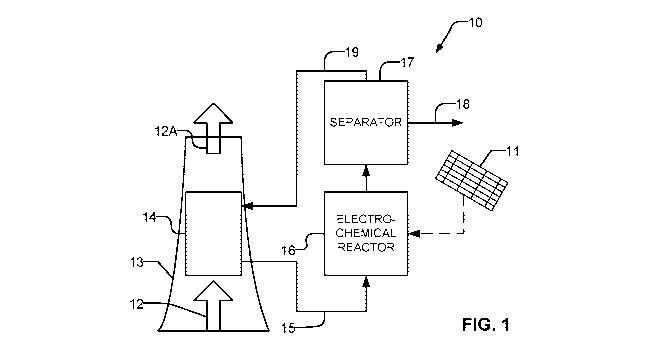
[0022] Fig. 1 is a block diagram illustrating carbon capture apparatus
according to an
example embodiment of the invention.
[0023] Fig. 1A is a flow chart depicting a method for capturing carbon (in the
form of
CO2) and using the captured carbon to provide useful products according to an
example embodiment of the invention.
[0024] Fig. 2 is a block diagram of a system for converting carbon dioxide
emissions
to useful materials according to an example embodiment of the invention.
[0025] Fig. 2A is a block diagram illustrating a bipolar membrane-based
C0321HCO3-
electrochemical reactor including ancillary equipment according to an example
embodiment.
[0026] Fig. 3 is a schematic diagram indicating electrochemical reactions that
occur
within a bipolar membrane-based C0321HCO3- electrolyzer cell according to an
example embodiment.
[0027] Fig. 3A is a schematic diagram indicating electrochemical reactions for
production of CO in a flow cell where the catholyte comprises 3M KHCO3 and the
anolyte comprises 1M KOH.
[0028] Fig. 3B is an organizational chart showing characteristics of a flow
cell that
may be selected to accomplish desired results and/or to control composition of
a
product gas.
[0029] Fig. 4A is an exploded perspective view of an example prototype bipolar
membrane-based C0321HCO3 electrolyzer cell. Fig. 4B is a schematic diagram
depicting a cross-section of the example prototype bipolar membrane-based C032-
/HCO3 electrolyzer cell shown in Fig. 4A. Fig. 4C is an exploded top view of
the
example prototype bipolar membrane-based C0327HCO3 electrolyzer cell shown in
7
CA 03098176 2020-10-23
WO 2019/204938
PCT/CA2019/050539
Fig. 4A.
[0030] Fig. 5 is a schematic diagram indicating the dimensions of the
prototype
membrane-based C0327HCO3 electrolyzer cell shown in Fig. 4A to 4C.
[0031] Fig. 6A shows cyclic voltammograms for the example prototype bipolar
membrane-based HCO3- electrolyzer cell shown in Figs. 4A to 4C operating with
two
electrolytic solution cathode feeds.
[0032] Fig. 6B is a graph showing Faradaic efficiency for CO production at
different
current densities between 25 to 100 mA cm-2 for the electrolytic solution
cathode
feeds in Fig. 6A using the example prototype bipolar membrane-based HCO3-
electrolyzer cell shown in Fig. 4.
[0033] Fig. 6C is a graph showing the dependence of partial current densities
for CO
measured at a constant cell potential of 3.0 V in a series of KHCO3 solutions
prepared
with different bicarbonate concentrations saturated with CO2 or N2.
[0034] Fig. 7A is a graph showing the concentration of CO2 leaving the flow
cell
during electrolysis of 3.0 M KHCO3 at 100 mA cm-2with a BPM and an AEM.
[0035] Fig. 7B is a graph showing Faradaic efficiency for CO as a function of
CO2
concentration at the outlet during the 2-h electrolysis of a 3.0-M KHCO3
solution at
100 mA cm-2 with a BPM and an AEM.
[0036] Fig. 7C is a graph showing the pH of bulk solution during electrolysis
of 3.0 M
KHCO3 at 100 mA cm-2with a BPM or AEM.
[0037] Fig 7D shows an example flow cell where a BPM separates a silver-coated
carbon gas diffusion electrode in the cathodic compartment and a Pt mesh anode
in
the anodic compartment.
[0038] Fig. 8 is a graph showing the temporal change in Faradaic efficiency
for CO
during a 5-h electrolysis of a N2-saturated 3.0-M KHCO3 solution at 100 mA cm-
2 with
the catholyte being replaced at 2.5 and 4 hours.
[0039] Fig. 9 is a graph showing Faradaic efficiency for CO as a function of
CO2
concentration at the outlet of an electrolysis cell comprising a BPM during
the 2-h
electrolysis of a 3.0-M K2CO3solution at 100 mA cm-2 .
[0040] Fig. 10 is a graph showing the temporal change in CO2 concentration at
the
outlet of an electrolysis cell during electrolysis of 3.0 M K2CO3 at 100 mA cm-
2with
8
CA 03098176 2020-10-23
WO 2019/204938
PCT/CA2019/050539
and without electrolysis.
Detailed Description
[0041] Throughout the following description, specific details are set forth in
order to
provide a more thorough understanding of the invention. However, the invention
may
be practiced without these particulars. In other instances, well known
elements have
not been shown or described in detail to avoid unnecessarily obscuring the
invention.
Accordingly, the specification and drawings are to be regarded in an
illustrative, rather
than a restrictive sense.
Definitions
[0042] "Bipolar membrane" or "BPM" is a membrane comprising plural layers
including an anion exchange layer on one side and a cation exchange layer on
another side. A bipolar membrane may comprise one or more layers between the
anion exchange layer and the cation exchange layer. For example, an
intermediate
layer may comprise a catalyst which facilitates dissociation of water into
protons and
hydroxide ions. The anion exchange layer may conduct hydroxide ions. The
cation
exchange layer may conduct protons. An example bipolar membrane is Fumasep
FBMTm available from FUMATECH BWT GmbH.
[0043] "Membrane electrode assembly" or "MEA" is an assembly comprising an
anode and a cathode separated by a BPM. The anode and the cathode may
respectively comprise catalysts suitable for promoting oxidation reactions at
the
anode and reduction reactions at the cathode.
[0044] "Flow cell" refers to an electrochemical cell in which a catholyte
and/or anolyte
are flowed through the cell while the cell is in operation. A non-limiting
example
construction of a flow cell provides flow plates separated by an MEA. An anode
flow
plate is located at the anode side of the MEA and a cathode flow plate is
located at
the cathode side of the MEA. The anode and cathode flow plates comprise flow
channels that respectively receive an anode feed and a cathode feed. A power
supply
is connected across the anode and cathode of the MEA in the flow cell to drive
oxidation reactions at the anode and reduction reactions at the cathode.
[0045] "Current density" is total current divided by the geometric surface
area of an
9
CA 03098176 2020-10-23
WO 2019/204938
PCT/CA2019/050539
electrode. For example, an electrode having an area of 100 cm2 carrying an
electrical
current of 20 Amperes would have a current density of 200 mA/cm2.
[0046] "Faradaic efficiency" (F.E.) is a measure of the efficiency with which
an
electron transfer reaction generates a desired product. Faradaic efficiency
can be
reduced by side reactions which create undesired products or by further
reactions
which consume the desired product after it is produced. F.E. for a gaseous
product k
may be determined in accordance with Equation 1.
rt rAkrõ
FE -
(Eq. 1)
where nk is the number of electrons exchanged, F is Faraday's constant (F=
96,485
C/mol), xk is the mole fraction of the gas kin the gaseous mixture analyzed,
Fõ is the
molar flow rate in molts, and / is the total current in A. The molar flow rate
may be
derived from the volume flow rate F by the relation F, = pFIRT, with p being
the
atmospheric pressure in Pa, R the ideal gas constant of 8.314 J/mol K and T
the
temperature in Kelvin.
Example Embodiments
[0047] Fig. 1 is a block diagram showing carbon capture apparatus 10 according
to
an example embodiment. Flue gas 12 or another gas containing CO2 to be
captured
(e.g. air, exhaust gas etc.) is carried in a duct 13 to a contactor 14. In
contactor 14
CO2 is contacted with a circulating solution with which it reacts to form
carbonate
and/or bicarbonate ions in the circulating solution. The circulating solution
may be an
alkaline solution. The circulating solution may, for example, comprise an
aqueous
solution of a strong base such as NaOH or KOH. Gases 12A output from contactor
14
have reduced carbon dioxide content.
[0048] The circulating solution is carried by an outlet line 15 to a flow
through
electrochemical reactor 16. At electrochemical reactor 16 the carbonate and/or
bicarbonate ions undergo electrochemical reactions which yield useful
chemicals.
[0049] The electrochemical reactions are facilitated by electrical power
supplied to
electrochemical reactor 16. The electrical power may, for example, come from a
source of green energy such as a solar array 11, wind energy or the like. In
some
embodiments flue gas 12 is emitted from an electrical power generator and
electrical
power for electrochemical reactor 16 is provided from the power generator.
CA 03098176 2020-10-23
WO 2019/204938
PCT/CA2019/050539
[0050] The useful chemicals are separated from the circulating solution at a
separator
17 and are taken off at outlet 18. In some embodiments the useful chemicals
are in
the gas phase and separator 17 is a gas/liquid separator. The useful chemicals
may,
for example comprise one or more of: carbon dioxide and carbon monoxide.
Electrochemical reactor 16 may also produce hydrogen gas. In some embodiments
the useful chemicals include syngas.
[0051] The circulating solution is circulated back to contactor 14 by conduit
19. One
or more pumps (not shown in Fig. 1) are provided to drive circulation of the
circulating
solution. Other design details of apparatus 10 such as fluid storage vessels,
sources
of chemicals to maintain the circulating solution at a desired pH and/or to
maintain
desired concentrations of chemical species in the circulating solution,
sensors for
monitoring operation etc. may optionally be present in apparatus 10 but are
omitted
from Fig. 1 for clarity.
[0052] Electrochemical reactor 16 of apparatus 10 may advantageously be
operated
at relatively low temperatures (e.g. temperatures below the boiling point of
the
circulating solution used). Electrochemical reactor 16 may, for example
operate at
ambient temperature and/or at a temperature of 150 QC or lower.
[0053] Electrochemical reactor 16 of apparatus 10 may advantageously be
operated
at or near to ambient pressure.
[0054] Fig. 1A is a flow chart depicting an example carbon capture method 100.
Method 100 takes in carbon dioxide from a gaseous source (e.g. air, flue gas,
exhaust gas) and yields useful carbon-containing chemicals. In block 102, CO2
is
captured through a chemical process that yields carbonates (C032-) and/or
bicarbonates (HCO3-) in an aqueous solution.
[0055] In some embodiments, the chemical process involves flowing ambient air
or
another gas containing carbon dioxide through a filter (e.g. contactor 14)
comprising a
liquid solvent sorbent. The sorbent removes CO2 from the carbon dioxide
containing
gas by absorbing the CO2. Examples of sorbents include but are not limited to
caustic alkaline solutions (e.g. NaOH or KOH). CO2 can undergo an acid-base
reaction with a caustic solution to yield a stable carbonate (e.g. sodium
carbonate) or
bicarbonate as reaction products. In an example case, CO2 molecules become
dissolved in the aqueous solution where they react to form anions such as
11
CA 03098176 2020-10-23
WO 2019/204938
PCT/CA2019/050539
bicarbonate anions.
[0056] The aqueous solution may, for example, have a pH in excess of 8. In
some
embodiments the solution has a pH in the range of 8-10. After absorbing CO2
the
solution contains ions of carbonate or bicarbonate. For example, the aqueous
solution
may have a [HCO3] or [C032-] of 0.5M or higher. In some embodiments at the
output
of block 102 the concentration of carbonate or bicarbonate ions in the aqueous
solution is in the range of about 0.5M to about 3.3M or higher. The aqueous
solution
may contain alkali metal ions (e.g. K , Nat) as counter cations.
[0057] Enzyme catalysts are optionally provided. Such catalysts may be
selected to
be catalysts that increase the efficiency of CO2 absorption. Example enzyme
catalysts
suitable for promoting carbon capture include, but are not limited to,
carbonic
anhydrases. These enzymes can advantageously withstand high temperatures (i.e.
>
100 C) and extreme alkalinity (i.e. pH > 10). Suitable enzymes can be native,
engineered and/or artificially produced.
[0058] In some embodiments, amine based solvents are used in place of caustic
solutions in block 102 to absorb CO2 from a carbon dioxide containing gas.
Example
amines that are suitable for use in association with gas treatment include,
but are not
limited to: aqueous alkanolamine (e.g. tri-ethyl amine), diethanolamine (DEA),
monoethanolamine (MEA), Methyldiethanolamine (MDEA), Diisopropanolamine
(DIPA) and Aminoethoxyethanol (Diglycolamine) (DGA).
[0059] In block 104, the solution containing the dissolved carbonates and/or
bicarbonates is supplied as catholyte at the cathode side of an
electrochemical flow
cell. The dissolved carbonates and/or bicarbonates are advantageously supplied
in
some embodiments in the absence of a gaseous CO2 feed.
[0060] A suitable anolyte is supplied at the anode side of the flow cell. In
some
embodiments the anolyte is basic. Examples of suitable anolytes include, but
are not
limited to, potassium hydroxide (KOH) and sodium hydroxide (NaOH). In other
embodiments the anolyte may be acidic.
[0061] In block 106, an electrical potential is applied between the anode and
cathode
of the flow cell to electrochemically reduce the aqueous carbonates and/or
bicarbonates into useful chemicals (e.g. CO2, H2, CO, etc.). In block 108, the
useful
chemicals are collected, stored and/or otherwise transported for further
processing.
12
CA 03098176 2020-10-23
WO 2019/204938
PCT/CA2019/050539
[0062] Directly supplying solutions containing bicarbonate (HCO3-) and/or
carbonate
(C032-) produced by carbon capture 102 to an electrochemical reactor as
illustrated,
for example, in Figs. 1 and 1A has the advantage that the concentrations of
these
species in saturated aqueous solutions can be quite high (e.g. up to about 3.3
M for
KHCO3 and about 8.1 M for K2CO3). This helps to facilitate high current
densities in
the electrochemical reactor. The direct electrochemical reduction of a HCO3-
or C032
solution advantageously avoids acidification of the electrolyte. In contrast,
CO2 has a
relatively low solubility in aqueous solutions and dissolution of CO2 in water
reduces
pH.
[0063] Fig. 2 is a block diagram illustrating a carbon capture system 200
according to
an example embodiment. System 200 comprises an electrochemical reactor 16
comprising at least one cell 216. Electrochemical cell 216 comprises an anode
160
and a cathode 161 separated by a BPM 162. Cathode 161 may be a gas diffusion
electrode.
[0064] An electrical potential is applied between cathode 161 and anode 160
from a
power supply 212. Power supply 212 may be configured to maintain a desired
electrical potential difference between cathode 161 and anode 160. Electrical
power
may be supplied to power supply 212 from any suitable source including solar
cells,
mains electricity or the like.
[0065] An aqueous feed 217 comprising C032- and/or HCO3- is supplied from a
carbon capture process 215 to cathode 161.
[0066] Cathode 161 comprises one or more catalyst materials 161A (see Fig. 3)
that
promote electrochemical reduction reactions which yield CO or another desired
product.
[0067] Feed 217 now carrying the desired product is carried to a separation
stage
218 where the product is taken off or used. In embodiments where the
product(s) are
gaseous the separation stage may comprise a gas liquid separator. In a simple
embodiment the gas liquid separator may comprise a closed compartment having
an
upper section in which gases may be collected. In other cases separation stage
218
may comprise a selective membrane or other technology for separating the
desired
products from the flow of feed 217 exiting reactor 16.
[0068] It is generally desirable to collect product gases as soon as
practical.
13
CA 03098176 2020-10-23
WO 2019/204938
PCT/CA2019/050539
Produced CO2 can revert to bicarbonate if it is not collected and taken out of
the
catholyte. For this reason it can be desirable to provide separation stage 218
at the
outlet of a cell 216 and/or to provide volumes in which gaseous products can
be
collected and withdrawn from one or more locations inside cell 216.
[0069] A system 200 as illustrated in Fig. 2 may, for example be operated to
generate
CO directly from C032- and/or HCO3- produced from carbon capture process 215
without first extracting CO2 from feed 217.
[0070] Reactor 16 is shown in Fig. 2 as a single cell 216 for ease of
illustration.
However, in practical implementations reactor 16 may comprise multiple cells
which
may have fluid connections in parallel, in series or in series-parallel as
known in the
art. Such cells may have separate power supplies or groups of cells may share
a
power supply. Where a single power supply provides electrical power to drive
plural
cells, the plural cells may be electrically connected to the power supply in
series, in
parallel or in series-parallel.
[0071] In some embodiments, heat derived from the operation of reactor 16 may
be
used in other parts of a production plant.
[0072] A reactor 16 can be optionally scaled to include multiple cells 216
each
connected to receive C032- and/or HCO3- from feed 217. Cells 216 may, for
example,
be arranged in stacks. Stacks of cells 216 can be connected in parallel such
that a
single aqueous stream is split to simultaneously feed multiple cells 216, in
series
where each subsequent cell receives a feed containing reduced concentrations
of
C032- and/or HCO3- or in a configuration comprising a combination of parallel
and
series connections.
[0073] An electrochemical reactor 16 may include various ancillary systems.
Fig. 2A
is a block diagram illustrating an electrochemical reactor 16 which includes
pumps
250A and 250B which are respectively connected to deliver flows of anode feed
251A
and cathode feed 251B to anode 160 and cathode 161 respectively. In some
embodiments an output stream from cathode 161 is processed by one or more
filters/separators 218. Filters/separators 218 may operate to deliver desired
products
(e.g. CO) to collector 218A and/or recirculate the output stream from cathode
161
back to cathode feed 251B and/or back to a carbon capture process (not shown
in
Fig. 2A). Anode Feed 251A may similarly be recirculated through pump 250A.
14
CA 03098176 2020-10-23
WO 2019/204938
PCT/CA2019/050539
[0074] In some embodiments, collector 218A comprises additional chemical
processing stages operative to convert the collected gases to other chemicals.
For
example, collector 218A may provide processing stages for converting collected
syngas to:
= methanol and/or its derivatives (e.g. formaldehyde, acetic acid, methyl
tert-
butyl ether, dimethlyl ether) via a methanol synthesis process,
= synthetic diesel fuel via Fischer-Tropsch and/or
= ethylene and other C2+ products using an electrochemical reactor that
uses
gaseous CO and/or CO2 as feedstock.
[0075] Fig 2A also shows a controller 260. Controller 260 controls one or more
of:
= power supply 212,
= pumps 250A and/or 250B,
= a valve or other device that is operative to control how much of anode
feed
251A is recycled, etc.
based on manually inputs and/or inputs from sensor(s) 261.
[0076] Sensor(s) 261 may monitor one or more or any combination of:
= cell temperature,
= current supplied by power supply 212,
= voltage supplied by power supply 212,
= composition, pressure and/or temperature of anode feed 251A and/or
cathode
feed 251B entering cell 216,
= composition of cathode feed 251B leaving cell 216,
= etc.
[0077] Some non-limiting examples of functions that may be performed by
controller
260 include:
= regulating voltage and/or current being supplied by power supply 212 to
maintain a desired balance of carbon monoxide to hydrogen in cathode feed
251B leaving cell 216,
= decreasing a voltage and/or current being supplied by power supply 212 in
response to detecting more than a desired amount of side-reaction products,
= etc.
[0078] In some embodiments controller 260 comprises a suitably-programmed
CA 03098176 2020-10-23
WO 2019/204938
PCT/CA2019/050539
commercially available process controller. In general, controller 260 may be
implemented using specifically designed hardware, configurable hardware,
programmable data processors configured by the provision of software (which
may
optionally comprise "firmware") capable of executing on the data processors,
special
purpose computers or data processors that are specifically programmed,
configured,
or constructed to perform one or more steps in a method as explained in detail
herein
and/or combinations of two or more of these. Examples of specifically designed
hardware are: logic circuits, application-specific integrated circuits
("ASICs"), large
scale integrated circuits ("LSIs"), very large scale integrated circuits
("VLSIs"), and the
like. Examples of configurable hardware are: one or more programmable logic
devices such as programmable array logic ("PALs"), programmable logic arrays
("PLAs"), and field programmable gate arrays ("FPGAs")). Examples of
programmable data processors are: microprocessors, digital signal processors
("DSPs"), embedded processors, graphics processors, math co-processors,
general
purpose computers, server computers, cloud computers, mainframe computers,
computer workstations, and the like. For example, one or more data processors
in a
controller for a cell 216 or system of cells 216 may implement methods as
described
herein by executing software instructions in a program memory accessible to
the
processors.
[0079] Fig. 3 is a schematic diagram depicting some of the electrochemical
reactions
that are believed to occur in a cell 216 of an electrochemical reactor 16
according to
an example embodiment. Application of electrical potential between anode 160
and
cathode 161 causes electrolysis of water at BPM 162. Protons (H ) travel
toward
cathode 161. The protons react with dissolved HCO3- or C032- in the catholyte
to yield
CO2. This acid/base equilibrium reaction between HC037 C032- and H at or near
the
surface of BPM 162 may occur in accordance with Equations 2 and 3 below.
H + CO32- # HCO3-
(Eq. 2)
H + HCO3 # CO2 + H20
(Eq. 3)
At least some of the resulting CO2 undergoes catalyzed electrochemical
reactions at
16
CA 03098176 2020-10-23
WO 2019/204938
PCT/CA2019/050539
cathode 161 to yield CO. These CO2 reduction reactions may occur in accordance
with Equations 4-6 below.
2HCO3- + CO2 + 2e- CO + 2C032-+ H20
(Eq. 4)
2H+ + CO2 + 2e- CO + H20
(Eq. 5)
H20 + CO2 + 2e- CO + 20H-
(Eq. 6)
Protons and/or water may be reduced at cathode 161 in accordance with
equations 7
and 8 to yield H2.
2H20 + 2e- H2 + 20H-
(Eq. 7)
2H+ + 2e- H2
(Eq. 8)
[0080] In the Fig. 3 example embodiment, the reduction reactions that occur at
cathode 161 (e.g. as described in Equations 4, 6 and 7) generate reaction
products
that increase pH (increase alkalinity) of the catholyte. For example, these
reactions
may yield a weak base (e.g. C032) or a strong base (e.g. OH-). The generation
of
these bases increases the alkalinity of the catholye solution. Increasing the
alkalinity
of the catholyte solution advantageously increases CO2 solubility in HC031
C032
solutions. This may be beneficial when recycling the catholyte solution to
absorb
more ambient CO2 in the carbon capture process. In effect, the electrochemical
processing of the catholyte solution to convert carbonate ions and bicarbonate
ions
can have the advantageous side effect of regenerating the catholyte solution
for
reuse in carbon capture.
[0081] The proportion of produced CO2 that is converted to CO depends on
factors
including:
= the physical structure of cell 216 (e.g. the path length for CO2 to reach
catalytic sites on cathode 161, the surface area and distribution of catalytic
sites of cathode 161),
= the nature of the cathode catalyst (e.g. the activity of the cathode
catalyst, the
selectivity of the cathode catalyst for promoting reaction of CO2 to CO),
17
CA 03098176 2020-10-23
WO 2019/204938
PCT/CA2019/050539
= the characteristics of a cathode gas diffusion layer (GDL) (a more
hydrophobic GDL tends to reduce production of CO, possibly because a
hydrophobic GDL makes it more likely that CO2 will be pulled into the GDL
before it reacts to form CO. A thinner GDL tends to increase CO production. A
thin and/or non-hydrophobic GDL can select for higher CO production while a
thicker and/or more hydrophobic GDL can select for higher CO2 production),
= the applied electrical potential, and the characteristics of the
catholyte (e.g.
concentrations of dissolved species, pH).
The ratio of CO to CO2 produced by cell 216 may be varied by altering one or
more of
these parameters.
[0082] It is desirable that cathode 161 and in particular the gas diffusion
layer and
catalyst of cathode 161 are located close to BPM 162. In some embodiments
cathode
161 is in contact with BPM 162. In some embodiments cathode 161 is spaced
apart
from BPM 162 by a distance of 100 m or less.
[0083] Fig. 3A illustrates electrochemical reactions for production of CO in a
flow cell
where the catholyte comprises 3M KHCO3 and the anolyte comprises 1M KOH.
[0084] Fig. 3B is an organizational chart depicting characteristics of an
electrochemical reactor 16 that may be adjusted to tune the operation of the
electrochemical reactor. These characteristics include but are not limited to:
electrical
operating conditions 151, flow plate dimensions 152, and MEA Design 153.
[0085] Examples of electrical operating conditions 151 include but are not
limited to a
potential applied between anode and cathode, the magnitude of current driven
between the anode and cathode and any time variation of the potential and/or
current.
[0086] Adjusting electrical operating conditions 151 can alter the ratios of
product
chemicals yielded by electrochemical reactions (e.g. CO2, H2, CO, etc.). For
example,
the applied current or potential can be increased to generate more CO2 and H2.
This
will cause CO production to decrease, since the total molar amount of reduced
products (e.g. H2 and CO) is proportional to the total current supplied (in
accordance
with Faraday's Law).
[0087] In some embodiments, electrical operating conditions 151 are tuned to
reduce
HCO3- and/or C032- and to yield CO2:CO:H2 at a molar ratio of about 2:1:1.
18
CA 03098176 2020-10-23
WO 2019/204938
PCT/CA2019/050539
[0088] In some embodiments, electrical operating conditions 151 is tuned in
synchrony with other flow cell specifications to reduce HCO3- and/or C032- to
yield
CO2:CO:H2 at molar ratios ranging from 4:3:1 to 5:1:4. Example flow cell
specifications that can be adjusted include, but are not limited to, gas
diffusion
electrode properties such as ionomer content, Ag catalyst loading, PTFE
content,
GDL porosity, GDL thickness, etc.
[0089] Examples of flow plate characteristics 152 include but are not limited
to: flow
plate surface area, flow plate channel width, and flow field patterns within
the flow
plate. A flow plate may have channels that provide a serpentine flow field, a
flow field
comprising parallel channels, a flow field comprising an interdigitated
pattern, etc. The
anode flow plate and the cathode flow plate may have the same or different
flow plate
configurations 152.
[0090] At higher current densities, an interdigitated pattern may desirably
provide
improved Faradaic efficiency. With an interdigitated pattern an input to the
flow field
connects to a first set of channels and an output from the flow field connects
to a
second set of channels. The first and second sets of channels are
interdigitated.
Catholyte (or anolyte) can flow from a channel of the first set of channels to
a channel
of the second set of channels through a porous part of the cathode (or anode).
[0091] Examples of catholyte properties 153 include but are not limited to:
pH,
concentration of bicarbonate and/or carbonate, other species present, solvent
etc.
Some embodiments prefer catholyte concentrations in the range between 1.5 M to
3.0 M HCO3-. Some embodiments prefer catholyte pH in the range of 8-10.
[0092] Examples of anolyte properties 154 include but are not limited to: pH,
species
present, solvent etc. Appropriate selection of anolyte can reduce the
electrical
potential required across a cell 216 and therefore increase energy efficiency.
For
example, operating the anode under acidic conditions may facilitate reduced
potential
if the membrane being used is a cation exchange membrane opposed to a bipolar
membrane, especially when the anode catalyst is selected to promote the oxygen
evolution reaction under acidic conditions. Some embodiments prefer a KOH
anolyte
solution having concentrations in the range between 1 M to 5 M KOH. Such
solutions
are not too caustic and may advantageously avoid corroding the electrolyzer
cell.
[0093] Examples of MEA design characteristics 155 include but are not limited
to
19
CA 03098176 2020-10-23
WO 2019/204938
PCT/CA2019/050539
selecting materials and physical characteristics for anode 160, cathode 161
and BPM
162.
[0094] In some embodiments anode 160 is porous. For example, anode 160 may
comprise a layer of a porous foam of a suitable metal (e.g. nickel). Anode 14
may
additionally comprise an anode catalyst 160A suitable for promoting oxidation
reactions. In a preferred embodiment, anode 160 operates under basic
conditions
(i.e. pH in the range of 7 to 14). In basic conditions, efficient and earth-
abundant
transition metal catalysts may be used as the anode catalyst. Examples of
suitable
anode catalysts in the case where the anode is operated under basic conditions
are
Ni, and FeNi0x. Precious metals such as Pt or Ir may also be used as anode
catalysts. In an example embodiment, anode 160 comprises a layer of a porous
metal
(e.g. a porous nickel foam) that acts as a catalyst for an anode-side
electrochemical
reaction and is formed to provide a diffusion layer.
[0095] In some embodiments cathode 161 comprises a gas diffusion layer. The
gas
diffusion layer may comprise porous materials such as carbon felt, carbon
paper,
carbon cloth, a sintered gas diffusion layer, or the like. Cathode 161
additionally
includes a cathode catalyst 161B suitable for promoting the reduction of
carbonates
and/or bicarbonates to CO or other desired products.
[0096] An example of a suitable cathode catalyst is silver (Ag). Silver
catalysts tend to
promote reactions which yield CO. It is possible to produce CO2:CO:H2at a
1:0:1 ratio
by using a cathode catalyst that does not promote reactions that yield CO.
Another
example cathode catalyst is gold (Au). Other examples for cathode catalyst
161B are
any late first (or second) row transition metal catalyst, post-transition
metals (e.g.
bismuth), alloys of suitable metals, suitable metal oxides, mixtures of silver
and gold,
etc. Some embodiments use bi and tri-metal mixed metal materials as cathode
catalyst 161B. A highly active cathode catalyst 161B may be chosen to promote
the
electrochemical production of desired products when carbonates and/or
bicarbonates
are supplied to the electrochemical reactor.
[0097] Cathode catalyst 161B may, for example, be provided in the form of an
electrocatalyst ink. The electrocatalyst ink may optionally comprise a
dispersion of
silver nanoparticles, a conductive ionomer, PTFE to control water content,
etc.
[0098] BPM 162 may comprise materials that have properties including, but not
CA 03098176 2020-10-23
WO 2019/204938
PCT/CA2019/050539
limited to: high proton conductivity by the cation exchange layer, high
hydroxide
conductivity by the anion exchange layer high resistance to electrons,
impermeability
to carbon products, long-term chemical stability, long-term thermal stability
and/or
high mechanical robustness. Bipolar membranes suitable for use as BPM 162 are
commercially available from companies such as FUMATECH BWT GmbH of
Germany.
[0099] In some embodiments, the temperature of cells of an electrochemical
reactor
are adjusted. Increasing temperature may advantageously encourage the
conversion
of HCO3- and/or C032- to CO2 within the flow cell. In some embodiments a
temperature of the cathode in an electrochemical reactor as described herein
is
maintained to be in the range of about 40 C to 70 C. In some embodiments the
cells
of an electrochemical reactor are operated at ambient temperature (e.g. room
temperature) as raised due to the effect of heating arising from the operation
of the
cells of the electrochemical reactor.
[0100] The apparatus and methods described herein may be varied. For example:
= electrochemical cells as described herein may be applied to process
bicarbonate and/or carbonate from sources other than carbon capture (e.g.
converting HCO3- found in seawater into CO and H2);
= a bipolar membrane may be provided by combining a cation exchange
membrane and an anion exchange membrane.
= a cation exchange membrane ("CEM") may be used in place of a bipolar
membrane with suitable adjustments made to other electrochemical reactor
design features, such as providing an acidic anolyte (e.g. H2SO4, HCI, H3PO4).
The acidic anolyte may, for example, have a concentration in the range of
about 0.1 M to 10 M. Where an acidic anolyte is used it can be desirable to
use an acid-stable anode catalyst (e.g. Ir, Ru, Cr or Pt) or its oxide
derivate on
an acid stable conductive support (e.g. Pt, Ti). Protons from the anode side
may
pass through a CEM to the cathode side.;
= an anion exchange membrane ("AEM") may be used in place of a bipolar
membrane with suitable adjustments made to other electrochemical reactor
design features to yield reactions at the AEM and catalyst according to
Equations 9 and 10 respectively
21
CA 03098176 2020-10-23
WO 2019/204938
PCT/CA2019/050539
OH- + HCO3- # C032- + H20
(Eq. 9)
H20 + CO2 CO + 20H
(Eq. 10)
= alternative cathode catalysts may be used (alone or with one or more
other
catalysts as described herein) to yield products other than or in addition to
carbon dioxide, carbon monoxide and hydrogen.
Prototype Embodiment
[0101] Fig. 4A is an exploded view of a prototype membrane-based C0327HCO3-
electrolyzer cell 400 that has been made and used to verify the operation of
cells as
described herein. Fig. 4B is a schematic diagram depicting a cross-section of
cell
400. Cell 400 comprises membrane electrode assembly (MEA) 410. MEA 410
comprises cathode 412, anode 414 and a membrane 416. In the prototype each of
cathode 412 and anode 414 had dimensions of 2.5 cm x 2.5 cm of which a 2 cm x
2
cm area was exposed for an active area of 4 cm2.
[0102] In the prototype embodiment, cathode 412 comprises a silver
nanopowder/Naf ion TM catalyst mixture deposited on a 2.5 x 2.5 cm carbon
paper gas
diffusion layer (GDL). The GDL has a high surface area.
[0103] In the prototype embodiment, anode 414 comprises a 2.5 x 2.5 cm nickel
foam
layer which acts as both a diffusion layer and as an OER catalyst in basic
conditions.
The nickel foam was model EQ-BCNF-16m available from MTI Corp of Richmond
California USA.
[0104] Cathode 412 may be prepared, for example, using an ultrasonic spray
coating
method, a hand coating method and/or an airbrush method. In the prototype
embodiment, cathode 412 comprises a GDL and a cathode catalyst prepared by
mixing 32 mg of silver nanopowder (Sigma, trace metal basis, >99%), 800 A of
deionized water, 800 A of isopropyl alcohol and 60 I of Nafion 117 solution
(Sigma,
wt% in a mixture of lower aliphatic alcohols and water). In some embodiments,
cathode 412 can be prepared by spray-coating a catalyst ink on a 4-cm2 area of
carbon cloth (Fuel Cell Store, GDL-CT) and drying the catalyst ink under a
gentle air
stream. In some embodiments, a mask (e.g. Kapton TM tape) can be applied to
avoid
depositing catalysts outside the active area of the GDL of cathode 412.
[0105] In the prototype, both bipolar membranes and anion exchange membranes
22
CA 03098176 2020-10-23
WO 2019/204938
PCT/CA2019/050539
(AEMs) were tested as membrane 416 to verify the operation of cells as
described
herein. Bipolar membranes were purchased from FuMA-tech and stored in 1M NaCI
Solution.
[0106] MEA 410 is sandwiched between cathode flowplate 423 and anode flowplate
443. The assembly comprising MEA 410, cathode flowplate 423 and anode
flowplate
443 is in turn clamped between cathode housing 420 and anode housing 440.
Gaskets 422A, 422B, 442A, and 442B seal cell 400.
[0107] Cathode housing 420 includes ports 425, 426 connected to deliver
cathode
feed to cathode 412 by way of cathode flow field 424 in cathode flowplate 423
and to
receive reaction products such as CO formed at the cathode of cell 400. Anode
housing 440 includes ports 445, 446 connected to deliver anolyte to anode 414
by
way of anode flow field 444 in anode flowplate 443 and to recover product
(e.g.
oxygen gas) formed at the anode of cell 400.
[0108] Cathode housing 420 and/or anode housing 440 may be made from suitable
materials such as stainless steel or other materials that are chemically inert
to anode
and/or cathode feeds. Cathode housing 420 and anode housing 440 can be made
from the same or different materials.
[0109] Flow plates 423 and 443 respectively provide electrical connections
between
the negative output of a power supply (not shown in Figs. 4A, 4B, 4C) and
cathode
412 and the positive output of the power supply and anode 414. To this end
flow
plates 423 and 443 are in electrical contact with the electrically conductive
diffusion
layers of anode4 and cathode 414 respectively. Flow plates 423 and 443
respectively
deliver cathode feed to cathode 412 and anolyte to anode 414 by way of
corresponding flow fields 424, 444. In the prototype, flow fields 424, 444
were each
made up of serpentine channels 1.5 mm wide and 1.5 mm deep separated by 1-mm
ribs.
[0110] Cathode flowplate 423 and anode flowplate 443 may be made from the same
or different materials. Cathode flowplate 423 may comprise materials that are
chemically inert to the cathode reactant (e.g. C032-, HCO3-, etc.), stable in
acidic
conditions, electrically conductive, and/or unreactive towards the C032-/HCO3
reduction reaction.
[0111] Anode flowplate 443 may comprise materials that are chemically inert to
the
23
CA 03098176 2020-10-23
WO 2019/204938
PCT/CA2019/050539
anode electrolyte, stable in basic conditions, electrically conductive, and/or
unreactive
toward the oxygen evolution reaction (OER). In the prototype, cathode
flowplate 423
and anode flowplate 443 are made from grade 2 titanium and 316 stainless steel
respectively.
[0112] Gaskets 422A, 422B, 442A, and 442B may be made from the same or
different materials. Gaskets 422A, 422B, 442A, and 442B may comprise materials
with good chemical inertness and/or high compressibility to maintain gas-tight
and
liquid-tight seals between different layers of cell 400. In the prototype
embodiment,
gaskets 422A, 422B, 442A, and 442B comprise 1.5-mm thick chemical resistant
compressible polytetrafluoroethylene (PTFE).
[0113] Holes formed in gaskets 422A, 442A facilitate fluid delivery between
the ports
on housings 420, 440 and flowplates 423, 443. Cut outs in gaskets 422B and
442B
(in the prototype 2 x 2 cm square cutouts) expose active areas of anode 412
and
cathode 424 to the corresponding flow fields 424, 444.
[0114] Fig. 5 is a schematic diagram showing dimensions (cm) of components of
the
prototype cell.
Experimental Electrolysis and Product Analysis.
In experiments using this prototype cell, an aqueous solution of either 3.0 M
K2CO3 or
3.0 M KHCO3 with 0.02 M ethylenediaminetetraacetic acid (EDTA, 99%, Sigma
Aldrich) added to remove impurities was purchased from Alfa Aesar and supplied
as
a cathode feed. The cathode feed was continuously bubbled with either N2
(Praxair,
99.9%) or CO2 gas (Praxair, 99.9%) at 50 sccm and delivered to the cathode
through
a peristaltic pump at a rate of 50 mL min-1.
[0115] 1 M KOH was recirculated through the anode compartment at a flow rate
of 50
mL min-1 using a peristaltic pump. Samples of the gaseous headspace of the
electrolyzer outlet were vented into the gas-sampling loop of a gas
chromatograph
(e.g. Perkin Elmer; Clarus 580 GC). Each GC run detected products such as CO
and
H2.
[0116] The GC was equipped with a packed MolSieve 5 A column and a packed
HayeSepD column. Argon (Praxair, 99.999%) was used as the carrier gas. A flame
ionization detector with methanizer was used to quantify CO concentration and
a
thermal conductivity detector was used to quantify hydrogen concentration.
24
CA 03098176 2020-10-23
WO 2019/204938
PCT/CA2019/050539
[0117] The cathode solution was analyzed by 1H nuclear magnetic resonance
(NMR)
after electrolysis.
[0118] Electrochemical measurements were conducted at room temperature and
pressure using a potentiostat (CH instruments 660D with a picoamp booster)
through
two-electrode cell measurements. Electrochemical measurements were made with a
two-electrode system with Ni foam as the anode and Ag spray-coated on carbon
paper as the cathode.
[0119] Anodes were prepared by cutting as-purchased nickel foam to size. A
standard cleaning procedure as described in reference 46 was used to clean
both the
carbon GDL and nickel foam. The BPMs (FuMA-tech; Fumasep FBM) were stored in
1 M NaCI solution prior to assembly in the cell. A fresh cathode, anode, and
BPM
were used for each electrolysis test.
Electrolysis of KHCO3 with and without CO2 feed.
[0120] Cyclic voltammograms (CVs) were collected between potentials of -1.5V
and -
3.5V in the prototype cell for 3.0 M KHCO3 bubbled with CO2 gas, and 3.0 M
KHCO3
bubbled with N2 gas (Fig. 6A). Faradaic efficiencies of CO (F.E.co) for the
two
solutions were measured between current densities of 25 and 100 mA cm-2 in 25-
mA
-2
cm increments (Fig. 6B). The viability of the flow cells 216, 400 towards CO2
reduction was confirmed by results from the CO2-saturated 3.0 M KHCO3 solution
(see Fig. 6A): The CV exhibits a sharp rise in current density at -2.5 V. A
current
density of 90 mA cm-2 at -3.5 V was measured. A moderate F.E.co of 62% is
exhibited
at low current densities (20 mA cm-2), falling to 21% at higher current
densities (100
mA cm-2) (see Fig. 6B). The dependence of partial current densities for CO
measured
at a constant cell potential of 3.0 V in a series of KHCO3 solutions prepared
with
different bicarbonate concentrations saturated with CO2 or N2 was measured
(Fig. 6C)
[0121] The electrochemical reduction of bicarbonate and carbonate solutions in
prototype flow cell 400 in absence of a CO2 supply was investigated. CVs were
collected in the -1.5 to -3.5 V cell potential range which show similar
reductive sweep
profiles to the CO2-saturated solution (Fig. 6A). Peak current densities of
100 mA cm2
and 90 mA cm-2 were measured for the KHCO3 bubbled with CO2 gas and KHCO3
bubbled with N2 gas solutions respectively. Electrochemical reduction of N2-
saturated
3.0 M KHCO3 solution showed a F.E.co of 80% at a current density of 25 mA cm-
2,
CA 03098176 2020-10-23
WO 2019/204938
PCT/CA2019/050539
falling to 36% at 100 mA cm-2(Fig. 6B). The F.E.co is greater (or at least
equal) for
the N2-saturated 3.0 M KHCO3 solution compared with the analogous CO2-
saturated
solution at every current density between 25 and 100 mA cm-2. This result is
believed
to be the first observation of KHCO3 reduction to CO in the absence of a
gaseous
CO2 feed, and the first example of electrochemical reduction of KHCO3 to a
reduced
carbon product other than formate.
Concentration and pH of dissolved CO2 after electrolysis.
[0122] The concentrations of dissolved CO2 in each of the three electrolytes
were
calculated. [CO2] values in bulk solution were resolved using the bicarbonate
and
carbonate equilibria equations (Eq. 11 and 12, respectively) in conjunction
with the
pH as measured by a pH meter.
CO2 + H2O # H+ + HCO3- pKai = 6.4
(Eq. 11)
HCO3-+ H2O # C032- +1-1 pKa2 = 10.3
(Eq. 12)
[0123] The pH for CO2-saturated 3.0 M KHCO3 solution was measured to be 8.2
giving a [CO2] = 33 mM. This concentration is consistent with the reported
value of
saturated CO2 aqueous solution. The pH for N2-saturated 3.0 M KHCO3
electrolyte
was measured to be 9.0, giving [CO2] = 6.6 mM which is significantly lower
than [CO2]
in the bicarbonate solution bubbled with CO2. The environment at the surface
of the
electrode may have a higher pH due to the consumption of protons during the
electrochemical formation of either H2 or CO, resulting in a lower localized
concentration of CO2 compared to the bulk solution.
[0124] Despite the 5-fold difference in CO2 concentration between the CO2-
saturated
and N2-saturated bicarbonate solutions, these two solutions exhibit similar
performance for the electrochemical production of CO in the prototype flow
cell.
Experiment Conclusions.
[0125] The above experiments using prototype cell 400 demonstrates that
bicarbonate and carbonate can be reduced to CO in flow cells 216, 400 without
the
supply of gaseous CO2 to the electrolyte. The 3.0-M KHCO3 system without a CO2
26
CA 03098176 2020-10-23
WO 2019/204938
PCT/CA2019/050539
feed was observed to have greater (or at least equal) Faradaic efficiency for
CO than
the CO2-fed solution. The experiments show that: (i) aqueous carbonate,
wherein
[CO2] is negligible, can be reduced into CO; and (ii) bicarbonate reduction
shows
strong dependence on [KHCO3] but no dependence on [CO2]. These experimental
results highlight a new strategy to convert aqueous bicarbonate and carbonate
species
directly into valuable commodities without the need to first extract CO2 gas
from a
bicarbonate or carbonate solution by an energy-intensive thermally-driven
decomposition step.
BPM vs AEM Experimental Testing
[0126] In a related experiment using prototype cell 400, an anolyte of 1.0 M
KOH was
circulated through the stainless flow plate and oxidized into 02 gas. 3.0 M
KHCO3
electrolyte solutions bubbled with N2 or CO2 were circulated through the
titanium flow
plate and reduced into CO at the cathode. The cathodic products were analyzed
by
gas chromatography (GC). Peristaltic pumps were used to circulate the anolyte
and
catholyte at 45 mL min-1 and 90 mL min-1 respectively. Gas flows (N2 or CO2)
were
set to 160 sccm.
[0127] Fig. 7A shows the CO2 concentration during a 3 hour experiment during
the
CO2 reduction reaction (CO2RR) with an AEM and with a BPM, during the hydrogen
evolution reaction (HER), and while circulating the 3.0-M KHCO3catholyte
without
performing electrolysis to obtain a baseline measurement. The concentration of
CO2
measured is enhanced during CO2RR and HER in the presence of a BPM compared
to the baseline measurement. The CO2 concentration decreases more slowly in
the
presence of a BPM, potentially indicating that CO2 is being generated at the
membrane.
[0128] Fig. 7B shows the faradaic efficiency for CO (F.E.co) achieved with an
AEM
and a BPM. In the presence of the BPM the F.E.co achieved after 2 hours is -
30%,
whereas in the presence of an AEM the F.E.co achieved after 2 hours is only -
2%.
The mechanism of HCO3- reduction in a flow-cell architecture is therefore
greatly
influenced by the BPM. Fig.7B shows that there is a linear relationship
between the
concentration of CO2 and F.E.co in the presence of both a BPM and AEM. At
10000
PPm there is a 20% F.E.co difference in performance between the AEM and BPM
27
CA 03098176 2020-10-23
WO 2019/204938
PCT/CA2019/050539
system. This difference may be accounted for by the pH environment within the
MEA.
Fig. 7C shows the change in bulk pH during CO2RR at 100 mA cm-2 for 3.5 hours
with a BPM (circle markings), an AEM (triangle markings), and without an
applied
current while circulating the 3.0-M KHCO3catholyte (square markings). Both the
BPM
and AEM system become more alkaline over time, however, the rate of increase
in
alkalinity is enhanced in the presence of the AEM. Fig 7D shows the formation
of CO2
bubbles during the electrolysis of HCO3- at a current density of 20 mA cm-2.
Fig. 7D
shows that enough CO2 is produced to exceed the solubility limits of CO2 in
aqueous
media.
[0129] In the presence of an AEM, HCO3- may act as a shuttle to bring CO2 to
the
surface. The F.E.co may be controlled by the equilibrium between HCO3- and
CO2.
The increase in bulk pH may be coupled to the decrease in system performance
due
to the equilibrium between HCO3- and CO2 being pH dependent. When electrolysis
occurs in the presence of a BPM, the [CO2] at the catalyst surface is no
longer solely
dependent on the bulk pH. The proton flux of the BPM in-situ generates CO2
which
can be further converted to CO at the cathode. A BPM in the presence of a 3.0-
M
C032- catholyte may predominantly produce HCO3- at the interfacial region
between
the BPM and the catalyst.
[0130] The inventors examined the possibility that the proton flux from the
BPM is
also responsible for the high F.E.co. The increase of F.E.co of -20% between
the
AEM and BPM (see Fig. 8C) may be attributed to the protons donors available at
the
catalyst surface. In the presence of a BPM, the proton flux from the BPM
regenerates
bicarbonate anions from carbonate, whereas with an AEM the hydroxide flux will
deplete the surface of bicarbonate anions leaving water as the sole proton
donor. The
depletion of bicarbonate at the catalytic surface can be implied by the bulk
pH
increasing more rapidly in the presence of an AEM than a BPM. The AEM must be
allowing cross-over of hydroxides from the anode which increases the
alkalinity within
the MEA. The relative pkA between bicarbonate and water is 6.4 and 14
respectively,
making bicarbonate a better proton donor than water. Further, it is possible
that
protons from the BPM can be directly coupled to the electrosorption of CO2 to
the Ag
surface. The difference in available protons likely accounts for the change in
faradaic
efficiency in the presence of an AEM or BPM when similar CO2 concentrations
are
present.
28
CA 03098176 2020-10-23
WO 2019/204938
PCT/CA2019/050539
[0131] In addition, there are likely two regions of local chemistry within the
MEA: a
more acidic region (lower pH) at the membrane-catalyst interface; and a more
basic
region (higher pH) within the catalyst. In the acidic region, HCO3 and CO32-
are
converted to CO2 and HCO3, respectively. This allows for CO2 to diffuse into
the
catalyst at high concentrations and a high local basic pH that would not
otherwise be
possible from sparging CO2 into the bulk catholyte. The basic pH region within
the
catalyst layer is due to the electrochemical reactions generating OH-. This
local region
of basic pH offers a unique opportunity for CO2 reduction due the
electrochemical
reduction potential of water being dependent on pH. As the pH increases, a
higher
over-potential is required to reduce water. Therefore, the local increase in
pH at the
catalyst surface may enhance the reduction of carbon species due to the shift
in over-
potential required to reduce H20 at pH 8 vs pH 14.
[0132] The inventors observe that the proton flux from the BPM in prototype
cell 400
enhances CO production from the flow cell by rapidly converting HCO3- to CO2
at the
membrane interface. Further, the BPM provides protons that can be used as
proton
donors in the form of H or regeneration of HCO3- from carbonate. Within the
catalyst,
the high local pH due to electrolysis inhibits the competitive hydrogen
evolution
reaction. Exploiting these two regions of local pH through MEA design
facilitates
tuning conversion of an aqueous HCO3- feed to provide mixtures of CO2, H2, and
CO
in desired ratios.
Additional Experimental Testing
[0133] In related experiments using prototype cell 400, an anolyte of 1.0 M
KOH was
circulated through the stainless flow plate and oxidized to yield 02 gas. Fig.
8 is a
graph showing the temporal change in F.E.co during a 5-h electrolysis of a N2-
saturated 3.0-M KHCO3 solution at 100 mA cm-2 with the catholyte being
replaced at
2.5 and 4 hours. Fig. 9 is a graph showing F.E.co as a function of [CO2] at
the outlet
during the 2-h electrolysis of a 3.0-M K2CO3 solution at 100 mA cm-2 in a flow
cell
comprising a BPM while the headspace in the flow cell was purged with 160 m
L/min
N2. Fig. 10 is a graph showing the temporal change in [CO2] at the outlet of a
flow cell
during electrolysis of 3.0 M K2CO3 at 100 mA cm-2 with and without
electrolysis. The
headspace of the cell was purged with N2 at 160 mL/min.
29
CA 03098176 2020-10-23
WO 2019/204938
PCT/CA2019/050539
Interpretation of Terms
[0134] Unless the context clearly requires otherwise, throughout the
description and
the claims:
= "comprise", "comprising", and the like are to be construed in an
inclusive
sense, as opposed to an exclusive or exhaustive sense; that is to say, in the
sense of "including, but not limited to";
= "connected", "coupled", or any variant thereof, means any connection or
coupling, either direct or indirect, between two or more elements; the
coupling
or connection between the elements can be physical, logical, or a combination
thereof;
= "herein", "above", "below", and words of similar import, when used to
describe
this specification, shall refer to this specification as a whole, and not to
any
particular portions of this specification;
= "or", in reference to a list of two or more items, covers all of the
following
interpretations of the word: any of the items in the list, all of the items in
the
list, and any combination of the items in the list;
= the singular forms "a", "an", and "the" also include the meaning of any
appropriate plural forms.
[0135] Words that indicate directions such as "vertical", "transverse",
"horizontal",
"upward", "downward", "forward", "backward", "inward", "outward", "vertical",
"transverse", "left", "right", "front", "back", "top", "bottom", "below",
"above", "under",
and the like, used in this description and any accompanying claims (where
present),
depend on the specific orientation of the apparatus described and illustrated.
The
subject matter described herein may assume various alternative orientations.
Accordingly, these directional terms are not strictly defined and should not
be
interpreted narrowly.
[0136] For example, while processes or blocks are presented in a given order,
alternative examples may perform routines having steps, or employ systems
having
blocks, in a different order, and some processes or blocks may be deleted,
moved,
added, subdivided, combined, and/or modified to provide alternative or
subcombinations. Each of these processes or blocks may be implemented in a
variety of different ways. Also, while processes or blocks are at times shown
as being
performed in series, these processes or blocks may instead be performed in
parallel,
CA 03098176 2020-10-23
WO 2019/204938
PCT/CA2019/050539
or may be performed at different times.
[0137] In addition, while elements are at times shown as being performed
sequentially, they may instead be performed simultaneously or in different
sequences. It is therefore intended that the following claims are interpreted
to include
all such variations as are within their intended scope.
[0138] Where a component (e.g. a software module, processor, assembly, device,
circuit, etc.) is referred to above, unless otherwise indicated, reference to
that
component (including a reference to a "means") should be interpreted as
including as
equivalents of that component any component which performs the function of the
described component (i.e., that is functionally equivalent), including
components
which are not structurally equivalent to the disclosed structure which
performs the
function in the illustrated exemplary embodiments of the invention.
[0139] Specific examples of systems, methods and apparatus have been described
herein for purposes of illustration. These are only examples. The technology
provided herein can be applied to systems other than the example systems
described
above. Many alterations, modifications, additions, omissions, and permutations
are
possible within the practice of this invention. This invention includes
variations on
described embodiments that would be apparent to the skilled addressee,
including
variations obtained by: replacing features, elements and/or acts with
equivalent
features, elements and/or acts; mixing and matching of features, elements
and/or
acts from different embodiments; combining features, elements and/or acts from
embodiments as described herein with features, elements and/or acts of other
technology; and/or omitting combining features, elements and/or acts from
described
embodiments.
[0140] Various features are described herein as being present in "some
embodiments". Such features are not mandatory and may not be present in all
embodiments. Embodiments of the invention may include zero, any one or any
combination of two or more of such features. This is limited only to the
extent that
certain ones of such features are incompatible with other ones of such
features in the
sense that it would be impossible for a person of ordinary skill in the art to
construct a
practical embodiment that combines such incompatible features. Consequently,
the
description that "some embodiments" possess feature A and "some embodiments"
possess feature B should be interpreted as an express indication that the
inventors
31
CA 03098176 2020-10-23
WO 2019/204938
PCT/CA2019/050539
also contemplate embodiments which combine features A and B (unless the
description states otherwise or features A and B are fundamentally
incompatible).
[0141] It is therefore intended that the following appended claims and claims
hereafter introduced are interpreted to include all such modifications,
permutations,
additions, omissions, and sub-combinations as may reasonably be inferred. The
scope of the claims should not be limited by the preferred embodiments set
forth in
the examples, but should be given the broadest interpretation consistent with
the
description as a whole.
32