Note: Descriptions are shown in the official language in which they were submitted.
CA 03098305 2020-10-26
System and method for an electrodynamic fragmentation
The invention relates to a fragmentation system for the electrodynamic
fragmentation of
material, comprising an inlet and an outlet for transporting material along a
transport
path, and at least one high-voltage pulse source for generating a high-voltage
discharge.
The document WO 2013/053066A1 describes a method for the fragmentation of
material
by means of high-voltage discharge. The material is introduced together with a
process
liquid into the process chamber.
It is an object of the invention to provide an improved system for the
fragmentation of
material.
This object is achieved by means of the fragmentation system having the
features of
patent claim 1. Furthermore, the object is achieved by means of the method for
electrodynamic fragmentation having the features of claim 16. Preferred and/or
advantageous embodiments of the invention and also other invention categories
are
evident from the further claims, the following description and the
accompanying figures.
A fragmentation system for the electrodynamic fragmentation of material is
proposed. In
particular, the fragmentation system is a continuously operable fragmentation
system.
The fragmentation system is configured especially for industrial fragmentation
of material
and/or fragmentation of material designed on a large scale. The fragmentation
is
preferably a segregated fragmentation. The system is suitable for a segregated
fragmentation according to size, type and/or composition. The material is
preferably an
inorganic material, and especially a composite material. The material can
comprise
organic components. By way of example, the material is concrete, slag, ceramic
or a
mining material. The fragmentation of the material preferably serves to obtain
secondary
raw materials, for example to obtain gravel, sand and/or cement substitute raw
materials.
CA 03098305 2020-10-26
- 2 -
The fragmentation system comprises an inlet and an outlet. By way of example,
the
fragmentation system comprises a housing and/or a process vessel, wherein the
inlet
and/or the outlet are/is arranged in the process vessel and/or in the housing.
The
material can be provided and/or fed in by means of the inlet. By way of
example, the inlet
is connected to a material store, for example a feed bunker, wherein the
material can be
stored in the feed bunker. The outlet serves, in particular, for transporting
away and/or
carrying away the fed material, the fragments thereof and/or the components
thereof and
constitutes for example a sink for the material. Between inlet and outlet,
material is
transported along a transport path in a transport direction. The transport
path can be a
straight path, a looped path or a jagged path. The transport path is a two-
dimensional or
three-dimensional path and/or route. The material transport between inlet and
outlet
suffices especially for conservation of material and/or mass, such that for
example the
mass of the fed material corresponds to the mass of the material transported
away at the
outlet. In particular, the fragmentation system can comprise a plurality of
outlets and/or
inlets.
The fragmentation system comprises at least one high-voltage pulse source. By
way of
example, the high-voltage pulse source is a Marx generator. The high-voltage
pulse
source, in particular each of the high-voltage pulse sources, comprises at
least one first
electrode and at least one second electrode for generating a high-voltage
discharge in a
discharge chamber. Hereinafter, first and second electrode are always
especially
mentioned by way of example. However, statements can correspondingly be
understood
analogously for a plurality of electrodes as well. Preferably, the discharge
chamber is
arranged between the first electrode and the second electrode. Alternatively,
the
discharge chamber can be arranged in an environment connecting the first
electrode and
the second electrode. The first electrode and the second electrode can be
embodied
such that they are of identical type or different. By way of example, first
electrode and/or
second electrode are/is a metal electrode, a graphite electrode or some other
electrode.
Preferably, the first electrode forms a cathode and the second electrode forms
an anode.
In particular, provision can also be made for first electrode or second
electrode to be
connected to ground potential, the remaining electrode being connected to a
higher or
lower potential.
The high-voltage pulse source is configured, in particular, to apply a working
voltage
between the first electrode and the second electrode in order to generate the
high-
voltage discharge. The high-voltage discharge can be effected for example from
the first
CA 03098305 2020-10-26
- 3 -
electrode through the material into the second electrode. The high-voltage
discharge is a
high-voltage pulse, in particular. The high-voltage pulse and/or the high-
voltage
discharge have/has a pulse length. The pulse length is preferably less than
one
microsecond, in particular less than 100 nanoseconds and especially less than
50 nanoseconds. The high-voltage pulse and/or the high-voltage discharge
preferably
have/has an energy of less than 500 joules per pulse, in particular less than
300 joules
per pulse and especially less than 100 joules per pulse. Preferably, the high-
voltage
pulse source is configured for generating high-voltage discharges with a
frequency of
more than 100 Megahertz. The high-voltage discharge and/or the high-voltage
pulse
have/has a pulse amplitude. The pulse amplitude is preferably identical to the
working
voltage and/or is between 10 kilovolts and 10 megavolts. Particularly
preferably, a pulse
amplitude is between 100 kilovolts and 5 megavolts.
The high-voltage source (generator) is embodied in particular in a variable
fashion or as
a flexible generator. In this regard, the energy consumption for the
respective material
can be optimized. In this regard, for the fragmentation of concrete, for
example, it is
possible to determine a minimum energy consumption of 2.3 kWhit (75 J /
pulse), which
is in the range of mechanical processing. In comparison with other
fragmentation
systems, the system according to the invention no longer has to be
acoustically isolated
and no excess energy is lost as thermal energy resulting in heating of the
process
medium (water, see below). Economic use of these technologies is possible with
such a
generator.
In particular, the rise time and/or amplitude and/or power and/or pulse energy
content
are/is settable at the generator.
The transport path has at least one fractionation section. The fractionation
section is for
example a partial section of the transport path. The fractionation section can
form a main
path or a bypass for the main path. The fractionation section preferably has a
length of
greater than 10 centimeters and especially greater than 50 centimeters. The
fractionation
section extends at least in sections between the first electrode and the
second electrode.
More specifically, the fractionation section comprises the first electrode and
the second
electrode and/or the first electrode and the second electrode form the
fractionation
section. The fractionation section extends through the discharge chamber. In
particular,
the entire fractionation section extends in the discharge chamber. The
fractionation
CA 03098305 2020-10-26
- 4 -
section can also be understood as the section of the transport path in which
the high-
voltage discharge is effected and/or can be effected.
The fragmentation system comprises a selection means for selectively
extracting the
material in the transport path. The selection means is preferably configured
to select
material which is situated on the transport path and/or is transported on the
transport
path, for example to select said material according to size, type and/or
shape. The
selection means is configured to channel material and/or fragments of the
material
having a diameter that is smaller than a minimum diameter past at least one
portion of at
least one of the fractionation sections or past at least one of the
fractionation sections.
The selection means serves to ensure that, in particular, only material having
a diameter
larger than the minimum diameter passes into a specific one of the
fractionation sections
and/or is transported in the fractionation section. The selection means forms
for example
a filter means, in particular a size filter. By way of example, material
and/or fragments of
the material smaller than the minimum diameter can be guided past the
fractionation
section by means of the selection means, for example on the bypass or a
detour. The
detour can also constitute a fall through a base or sieve. The selection means
is situated
in particular upstream (relative to the transport direction) of the
fractionation section, in
the fractionation section or downstream of the fractionation section.
Furthermore, the
fractionation section can be arranged in the region of the inlet.
In particular, the selection means is configured to separate fragments of the
material
having a diameter smaller than the minimum diameter which arise during the
upstream
treatment of the material by means of the high-voltage discharge.
The invention is based on the consideration that as a result of early
extraction of material
and small fragments, i.e. thus material of a certain size distribution, the
latter do not
occupy the subsequent downstream fractionation section and so the high-voltage
discharge is used there in a targeted manner for larger fragments. This
results in an
energy-efficient and high-throughput fragmentation system.
Optionally, the selection means can comprise the first electrode and second
electrode of
at least one high-voltage pulse source, alternatively also at least one
further electrode. In
particular, the first electrode and the second electrode can form the
selection means. By
way of example, the first and the second electrodes form a sieve structure or
a retention
means for material and/or fragments of the material having a diameter larger
than the
CA 03098305 2020-10-26
- 5 -
minimum diameter. This results in an at least partly integral embodiment of
selection
means and fractionation section.
Particularly preferably, the first electrode and the second electrode form a
rail. The
distance between the first electrode and the second electrode is then a rail
distance and
in particular is less than or equal to the minimum diameter. First electrode
and second
electrode can be connected mechanically, for example by means of struts, in
the rail.
Alternatively, first electrode and second electrode are mechanically
unconnected in the
rail. Electrical insulators, in particular, are a mechanical connection
between first
electrode and second electrode.
During transport through the fractionation section via the rails, material is
comminuted,
for example. If said material is small enough to fall between the rails
(selection), it is
selected within the fractionation section and guided out of the fractionation
section. In
this regard, it passes through only a portion of the fractionation section and
is channeled
past the remaining portion thereof (remaining length of the rails).
The invention is based on the fact that it is desirable to be able to recycle
composite
materials, for example concrete. The aim here is to obtain secondary raw
materials. By
way of example, it is endeavored to separate concrete and to re-use its
constituents. In
this case, in particular, the additives such as gravel and sand are
selectively freed from
the surrounding cement matrix. Manually operated systems and systems on a
laboratory
scale have been used for this hitherto. The throughput in such systems and/or
methods
has hitherto been less than three tons per hour. The degree of fragmentation
is also
often less than 80% in such systems. Higher throughput rates have been
attained to date
by means of mechanical methods, although such methods lack segregation and
have a
lower quality of the processed material. By way of example, microcracks arise
in gravel
grains as a result of a grinding process, and they reduce the mechanical
strength in RC
concrete.
In particular, the material has a different state at the inlet than at the
outlet; by way of
example, the material is bonded and/or lumpy at the inlet, while it is
fragmented and/or
separated at the outlet. The fragmentation is effected by the high-voltage
pulse, for
example. The fragments of the material have, in particular, a grain size of
typically less
than one centimeter.
CA 03098305 2020-10-26
- 6 -
The fragmentation system optionally provides for the fractionation section to
be
embodied as an inclined plane slipping downward. The fractionation section
slopes
downward in particular in the transport direction. The fractionation section
can slope
strictly monotonically. Alternatively, the fractionation section can be
embodied as an
inclined plane sloping downward with saddle and/or turning points. The
fractionation
section is embodied in particular such that material transport of the material
in the
transport direction can be effected without an electrical drive and/or is
effected on the
basis of gravitation and/or a downhill force. The fractionation section is
intended to
provide an efficient and energy-saving transport apparatus and in particular
to achieve
size and/or mass selection along the transport path on the basis of
gravitational effects in
the inclined plane. A transport device is thus provided which makes it
possible to
transport large amounts of material. Furthermore, the fragmentation system is
particularly energy-saving owing to the gravitational drive of the material
transport.
Optionally, provision is made for the first electrode and/or the second
electrode to have a
longitudinal extent. By way of example, first electrode and/or second
electrode are/is
embodied in the shape of a bar, for example in the shape of a round bar. The
longitudinal
extent of the first electrode and/or of the second electrode is preferably at
least ten times
the magnitude of the diameter of the electrode: the electrodes have an
electrode length,
wherein the electrode length is preferably greater than 10 centimeters, and in
particular
is greater than 50 centimeters. The first electrode and/or the second
electrode are/is
arranged with the longitudinal extent thereof in the same direction as and/or
parallel to
the transport direction. By way of example, first electrode and second
electrode are
arranged parallel to one another. It is particularly preferred for first
electrode and second
electrode to be arranged in a rail-shaped fashion and to form a top-hat rail,
for example.
By way of example, the material transport is effected in a transport plane,
wherein the
first electrode and the second electrode are arranged in the transport plane.
Alternatively, the first electrode and/or the second electrode can be arranged
in the same
direction as the transport plane but offset with respect thereto. This
configuration is
based on the consideration of providing a fragmentation system which is
obtainable in a
structurally simple way and enables an energy-saving and good fragmentation of
the
material.
According to the invention, bar-shaped and/or planar electrodes are used, in
particular,
which form a type of rail system which is used for further transport and
classification of
the material by way of inclination.
CA 03098305 2020-10-26
- 7 -
By way of example, the fractionation section forms a chute, wherein the chute
is
preferably delimited laterally by the electrodes. The high-voltage discharge
is preferably
effected at an angle of between 60 and 120 degrees with respect to the
transport
direction. Particularly preferably, the high-voltage discharge is effected
perpendicularly to
the transport direction.
In one preferred embodiment of the invention, at least two of the electrodes
form a chute
for the material, said chute sloping downward in the transport path in
relation to the
direction of gravity.
According to the invention, the material can slide and move on the electrodes.
The
situation can then occur that a piece of material slides along the entire
chute without
being comminuted sufficiently, e.g. because only its edges were fragmented.
Thus, it can
be extracted at the end of the electrode or chute and a stoppage of the
process can thus
be prevented. Said piece of material can then e.g. once again be introduced
into the
fractionation section or be fed to a further process, possibly a different
kind of process
(e.g. phasing out as landfill material or comminution by means of jaw crushers
for lower
quality use). The electrodes which are inclined (with respect to gravity or
with respect to
the horizontal) act as "passive conveyor belts". The transport speed of the
material can
be set by way of the optional angle setting (see below). In particular (see
below) the
distance between the respective pairs of electrodes in the chute is settable
in a variable
manner.
According to the invention, the electrodes which are optionally settable in
terms of
inclination act as chutes ("passive conveyor belts") for the material. The
material
transport and the speed thereof are thus effected to a significant extent by
the material's
own weight, depending on the size and weight of the material and the angular
position of
the "rail electrodes". In addition, the material flow or the speed thereof can
be supported
by the flow velocity of the surrounding medium (e.g. water, see below) with a
velocity
component at an inclination with respect to the rail system.
A corresponding chute makes it possible, in particular, to extract material at
the end of
the respective electrodes or chute - without cross-flow classification - only
on account of
gravity, optionally also through the assistance of a media flow. The exposed
material
need not - in the ideal case - be returned into the reaction vessel again
after extraction
CA 03098305 2020-10-26
- 8 -
from the reaction vessel. The electrodes are simultaneously, besides the
optional
medium (e.g. water), the transport medium that determines the path of the
material
through the reaction vessel.
Motorized conveying means, e.g. conveying belts, are not necessary here in
particular in
the actual fragmentation process. Such means can be provided e.g. if needed in
order to
feed material to the process or to carry it away from the process.
In one preferred variant of this embodiment, a length and/or an inclination
angle of at
least one of the electrodes of the chute and/or a distance between at least
two of the
electrodes of the chute are/is variable.
According to the invention, in particular the lengths and/or the inclination
angles of the
electrodes on which the material slides are variable ¨ the unfragmented
material moves
transversely with respect to the direction of gravity, if appropriate also
transversely with
respect to the transport medium, through the reaction vessel, while in
particular material
that is not to be fragmented (any further), e.g. fine material <2 mm, is
expelled as a
sludge fraction at the bottom directly via the shortest path (direction of
gravity). The
specific size of 2 mm relates e.g. to the treatment of concrete, since 2 mm
corresponds
to the grain size of sand. It is optionally possible to support the transport
by way of a
medium, which enables additional degrees of freedom (media type, media speed,
media
direction) in the process control.
In this regard, for each material, in particular, it is possible to establish
the optimum
residence time on an electrode or chute with a variable electrode distance in
order to
obtain the highest possible degree of exposure. On account of the variable
lengths of the
electrodes, the material has to cover a longer path in the process vessel than
if it simply
sank in the direction of gravity. As a result, an electrical pulse treatment
occurs more
frequently and the degree of exposure can be maximized as a result. Moreover,
more
material can be processed simultaneously by virtue of the longer process path,
which
crucially increases the throughput and thus enables an industrial application.
The residence times of the particles (material) in the process vessel are
variable
according to the invention and there is thus a possibility of optimization for
different
materials and/or fraction sizes (which require different residence times in
the process).
CA 03098305 2020-10-26
- 9 -
Electrode distances are in particular a maximum and/or a minimum of 2 mm, 4
mm,
8 mm, 16 mm, 32 mm, 64 mm. Intermediate magnitudes of the distances are also
selectable and freely settable as necessary.
One preferred embodiment provides for the chute or at least one of the
electrodes to be
vibratable. Vibrating the chute, etc. results in transport of the material
along the chute
being homogenized and clogging of material on the chute being made more
difficult.
Alternatively or additionally, given a suitable electrode shape, electrodes
which are
mounted rotatably about their own longitudinal axis and which support this
process are
also conceivable.
According to the invention, the electrodes thus participate not only in the
comminution
process, but also in the transport process.
Overall, an inclined rail system results, in particular, which makes it
possible to transport
material along the rail system, (e.g. constituents not yet or not
comminutable) and
through the rail system (e.g. sufficient comminuted/small constituents). Both
can also be
supported by a transport medium (water, oil, gas, etc.). The electrodes
crucially support
the transport process here.
In the case of the inclined rail system, constituents to be fragmented are
transported
further even if they are larger than the distance between the fragmentation
electrodes
(smaller particles fall through and larger particles slide along the inclined
planes
predefined by the rail electrodes) and can be extracted from the fragmentation
region
and either be introduced again elsewhere, or be transported as "waste product"
out of
the system and fed to a different use.
Such a rail system cannot become clogged as a result of the inclination. The
material is
transported further even without mechanical moving parts, i.e. on account of
gravity or
the downhill force. The material flow rate or the material speed can be set by
way of the
angular position of the rail system and can additionally be supported by a
flowing
medium. In addition, further transport can be supported by changing the
angular position
during operation, or (in particular slightly) vibrating the electrodes.
In the case of the gravity conveying according to the invention, the material
is not (only)
guided past the electrodes, but rather is guided and transported further
through or by
CA 03098305 2020-10-26
- 10 -
means of the electrodes. According to the invention, the material flow is not
(only) guided
past an electrode arrangement, rather the electrode arrangement itself is part
of the
material flow or - as it were - integrated into the material flow or directs
the material flow.
The electrode arrangement (chute / rail system which itself acts / is
manifested as an
electrode arrangement) is a decisive factor in ensuring that the material flow
can flow in
the first place.
According to the invention, the transport speed in the case of the electrode
arrangement
can be crucially concomitantly determined by the inclination of the
"chute/rail electrodes".
The transport speed then depends to a significant extent on the material's own
weight
(and no longer all that much on the piece size), the angular position of the
electrodes and
the material proportion having a fraction size smaller than the distance
between the rail
electrodes. This material proportion can then fall downward through the rail
system
(electrodes) and be transferred directly into the next process step with the
next smaller
fraction size. The material flow can additionally be concomitantly supported
by a flow of
the process liquid or of the possible process gas. This can likewise be
supported e.g. by
additional vibration or shaking of the rail electrodes.
The electrodes are situated in particular in the process liquid or a
correspondingly
suitable gas. The electrode feed can be effected from all sides. The material
or the
material flow is guided in particular completely or at least partly through
the electrodes in
the process chamber.
The electrode arrangement according to the invention in particular also allows
larger
fractionation section sizes than the maximum distance between the rail
electrodes /
electrode pairs. The latter lie on a rail system as electrodes and are also
guided by the
latter and can simultaneously be processed during material transport. A piece
size larger
than the respective distance between the rail electrodes is an essential
prerequisite here
to enable the respective fraction size also to be fragmented further in the
associated
processing step. In the case of a small piece size, the portions fall through
the rail
system and are fed to the next processing step.
The distance between the rail electrodes need not be uniform, but rather can
e.g. also
increase or decrease along the rail system (electrodes). This can be
concomitantly taken
into account during the adaptation of the next process step/process stage.
CA 03098305 2020-10-26
- 1 1 -
By means of the rail electrode system in the ideal case, the entire material
can be
completely fragmented in one pass. At the same time, insufficiently fragmented
portions
at the end of the rail electrodes can, by means of suitable conveying
measures, be fed
once again to the process or the fractionation section or be fed as
waste/rejects to a
different use (e.g. landfill, road construction, ...).
According to the invention, generally all the electrodes can be handled as
freely
"floating". An electrode pair can consist of two high-voltage electrodes, for
example,
which are raised momentarily to the same high voltage, but opposite signs, by
means of
a suitable high-voltage pulse generator.
A rail electrode system can consist of various electrode configurations, e.g.:
the simplest
configuration is a rail pair, wherein all that is essential is that a
corresponding high-
voltage pulse brings the individual electrodes to an electrical potential or
potential
difference such that a corresponding discharge suitable for the fragmentation
can take
place between the electrodes. In this case, the electrode potential of the
individual
electrode can be positive, negative or else at ground potential.
Other configurations of the rail electrode arrangement are a U- or ring-shaped
or star-
shaped arrangement of rail electrodes/electrode pairs; other arrangements are
also
conceivable.
One configuration of the invention provides for the fragmentation system to
comprise a
conveying apparatus for conveying a medium in a media conveying direction. The
fragmentation system can also comprise the medium. The medium is preferably a
liquid
and the medium is especially water. Alternatively, the medium can be gaseous.
The
conveying apparatus comprises for example a pump for conveying the medium. The
medium serves to support the material transport. By way of example, the
conveying of
the medium in the media conveying direction results in portions of the
material and/or
fragmentation elements of the material being carried along and/or entrained.
By way of
example, the medium serves for separating the fragments, for example on a
chromatographic principle. Particularly preferably, constant and/or continuous
media
conveying is provided. The media conveying of the medium is preferably
effected in the
transport direction especially along the transport path. More specifically,
the media
conveying is effected in the fractionation section. By way of example, the
medium is
flushed through the fractionation section and/or the transport path by means
of the
CA 03098305 2020-10-26
- 12 -
conveying device. The conveying apparatus serves for automatically extracting
fragments of the material.
In the case of the invention, the conductivity of the medium, in particular of
the process
liquid, is of secondary importance. On the basis of a specific pulse shape,
both very low
conductivity and high conductivity can be employed. In the course of the
process, the
conductivity of the process liquid generally increases as expected owing to
the release of
mineral constituents and salts.
A high conductivity is disadvantageous, rather, in other previous methods. A
high
conductivity increases the current flow through the process liquid, as a
result of which
more energy in the process liquid is converted as heat and results in the
heating of the
process liquid. As a result, a large portion of the energy required for the
fragmentation of
the material is lost in the form of heat. In addition, the process also has to
be cooled.
This causes the process to become distinctly inefficient, which is also
reflected in the
significantly higher power required per pulse.
The medium is, in particular, a medium which forms an insulator in the
parameter range
of the high-voltage discharge, for example for the pulse length and/or pulse
amplitude. In
particular, the breakdown strength of the medium is greater than the breakdown
strength
of room air. This configuration is based on the consideration that the high-
voltage
discharge is not effected via the medium, rather the high-voltage discharge is
effected
via the material and the material is thus fragmented. More particularly, the
medium
surrounds the material during material transport.
It is particularly preferred for the media conveying direction or at least one
component of
this direction to be directed counter to the transport direction. By way of
example, the
transport direction is directed from top to bottom in relation to the
direction of gravity, the
media conveying direction then being directed from bottom to top.
Alternatively, provision
can be made for the media conveying direction or at least one component of
this
direction to be in the same direction as the transport direction. The media
conveying
direction can be directed from top to bottom or from bottom to top. In
particular, provision
is made for the medium to be reusable and/or to be reused. By way of example,
after
passing through the transport path or after conveying has been effected, the
medium is
collected and conveyed once again. The collected medium is preferably filtered
and/or
cleaned in some other way before it is used for conveying again. This
configuration is
CA 03098305 2020-10-26
- 13 -
based on the consideration of firstly achieving a good separation of the
material
fragments and secondly providing a resource-saving fragmentation system.
In particular, the medium is water. In particular, the medium is distilled
water. The
medium preferably has a breakdown strength of greater than 20 kilovolts per
millimeter.
More specifically, the medium has a breakdown strength of greater than 40
kilovolts per
millimeter and especially a breakdown strength of greater than 60 kilovolts
per millimeter.
The medium can furthermore be embodied as oil, especially as dried oil. By way
of
example, the medium is a transformer oil. This configuration is based on the
consideration of providing a fragmentation system which has an improved degree
of
fragmentation and enables an energy-saving fragmentation of the material.
In particular, provision can also be made for the fragmentation system to
comprise a
returning apparatus. In this case, retained material, for example material
retained by the
selection means, is transported back in the direction of the inlet. Such
returned material
must then pass through the process once again, such that it is treated with
the high-
voltage discharge once again.
It is particularly preferred for the first electrode and the second electrode
to be arranged
at a distance smaller than the minimum diameter. The first electrode and the
second
electrode can be arranged parallel, convergently or divergently in the
transport direction.
By way of example, the first electrode and the second electrode are arranged
in a
wedge-shaped and/or v-shaped fashion. The convergently arranged first
electrode and
second electrode form for example the selection apparatus as a lateral
boundary; by way
of example, an excessively large chunk of material cannot be transported
further in the
transport direction if the distance between first electrode and second
electrode is smaller
than its diameter.
One configuration of the invention provides for the distance between the first
electrode
and the second electrode to be settable. By way of example, the distance
between first
Electrode and second electrode is selectable such that a desired degree of
decomposition, a grain size or a degree of fragmentation is achieved. If first
electrode
and second electrode are arranged convergently, then for example the angle
between
the first electrode and the second electrode can be variable. Said angle is
preferably set
such that the degree of fragmentation that is desired is achieved. Increasing
the angle
achieves the effect, for example, that fragments having a larger diameter can
be
CA 03098305 2020-10-26
- 14 -
transported faster and/or further in the transport direction. By way of
example, for a
reduction of the angle between first and second electrodes, a better
fragmentation is
achieved since larger fragment parts can be detained for longer and only small
components can advance. This configuration is based on the consideration of
providing a
fragmentation system which has an improved and/or settable degree of
fragmentation.
It is particularly preferred for the fragmentation system to comprise a
plurality of high-
voltage pulse sources. In particular, the fragmentation system comprises at
least two
high-voltage pulse sources and especially at least three high-voltage pulse
sources. The
high-voltage pulse sources or the electrodes thereof are arranged along the
transport
path. In particular, the plurality of high-voltage pulse sources form a multi-
stage system.
The fragmentation system comprising a plurality of high-voltage pulse sources
also
comprises a plurality of fractionation sections. The different high-voltage
pulse sources
and/or electrodes of the high-voltage pulse sources are arranged at different
fractionation
sections. The high-voltage pulse sources and/or fractionation sections are
arranged in
particular at a distance from one another and/or with no overlap with respect
to one
another. The high-voltage pulse sources are configured for outputting a high-
voltage
pulse and/or for generating a high-voltage discharge. In particular, the high-
voltage pulse
sources of the fragmentation system output different high-voltage pulses
and/or high-
voltage discharges. In particular, the working voltages of the plurality of
high-voltage
pulse sources in the fragmentation system are different. The working voltages
of the
high-voltage pulse sources are adaptable for example to the degree of
fragmentation
and/or to the grain size in the respective fractionation section. Besides the
working
voltage, provision can also be made for further pulse parameters to be
different for the
different high-voltage pulse sources, for example pulse length and/or pulse
frequency.
More specifically, provision can be made for the working voltage for the high-
voltage
pulse sources to become smaller along the transport path. This configuration
is based on
the consideration that a fragmentation system achieves an improved
fragmentation as a
result of the operation of different high-voltage pulse sources. In
particular, the working
voltages are adaptable to the respectively prevailing diameter and/or the
prevailing grain
size.
In particular, the individual fractionation sections 18 are arranged one above
another or
one beneath another (figure 1) in such a way that fragmented material smaller
than a
maximum size corresponding to the fractionation section can be transferred
directly into
the next fragmentation stage e.g. by means of gravity and support by a flowing
medium.
CA 03098305 2020-10-26
- 15 -
Alternatively, the fractionation sections 18 can also be arranged successively
or next to
one another or in a form that promotes a high throughput. In this case, the
material
transfer between the fractionation sections is effected to an increased extent
by means
of e.g. mechanical, electrical or else hydrodynamic transport methods. Other
methods
are also conceivable.
In particular, provision is made for the fragmentation system to have material
conveying
along the transport path of more than 10 tons per hour. Preferably, the
material
conveying along the transport path is greater than 20 tons per hour and
especially
greater than 50 tons per hour. The material is for example obtained from
and/or out of a
feed bunker and conveyed to a respective collecting container at one of the
outlets.
It is particularly preferred for the inclined plane to have a slope angle. The
slope angle is,
in particular, the angle between the fractionation section and/or the
transport path and a
horizontal. The slope angle is settable, in particular. It is particularly
preferred for the
slope angle to be settable such that a conveying speed and/or transport speed
of the
material are/is settable. By way of example, the angle can be set to be
steeper if more
material is intended to be supplied subsequently and/or the transport speed is
intended
to be increased. In the case of a build-up of material, provision can be made,
for
example, the slope angle to be reduced and the inclined plane to be set to be
flatter,
such that material present first is separated and/or fractionated.
Optionally, provision is made for the fractionation section and/or the
transport path to
have conveying structures. The conveying structures are embodied as rollers,
for
example. In particular, the conveying structures and/or the rollers are
embodied in a
driveless fashion, for example without a motor drive. The electrodes can be
part of the
conveying structures and/or can form the conveying structures. The conveying
structures
are configured to support and/or to promote the material transport.
One configuration of the invention provides for the fractionation section
and/or the
transport path to have sieve structures for extracting extremely small
fractions. Extremely
small fractions are for example fragments of material and/or material portions
which have
a diameter and/or a grain size smaller than a minimum diameter, e.g. smaller
than two
millimeters. Such extremely small fractions fall through the sieve structures,
for example,
and are thus quickly extracted from the further process, such that only coarse-
grained
fragments remain and are decomposed further. This configuration is based on
the
CA 03098305 2020-10-26
- 16 -
consideration of providing a fragmentation system which enables the
fragmentation of
material on an industrial scale. In particular, it is provided that a dynamic
equilibrium can
be established through the use of conveying structures, the conveying device,
the
inclined plane and/or the sieve structures and said dynamic equilibrium has
the effect
that material and/or material fragments can be fractionated and/or are
separated at a
plurality of locations, the throughput thereby increasing. In particular,
extremely fine
material and/or extremely small fractions which can no longer be fragmented
further
are/is automatically extracted and can be removed for example with the medium,
for
example water, such that this does not disturb and/or burden the process
further.
Provision can also be made for the fragmentation system to provide a drying
apparatus,
wherein the fragments are dried in the drying apparatus. Sorting of the
fragments is
likewise possible, for example direct sorting by means of an apparatus during
extraction
from the respective section. In this case, it is provided that the fragmented
material can
be reused and can be fed into a renewed material cycle for the production of
fresh
concrete, for example.
Further subject matter of the invention is constituted by a method, in
particular using the
fragmentation system described above, for the electrodynamic fragmentation of
material,
wherein material is transported from an inlet toward an outlet along a
transport path,
wherein the transport path has a fractionation section, wherein at least one
high-voltage
pulse source has at least one first electrode and at least one second
electrode, wherein
the high-voltage pulse source generates a high-voltage discharge in a
discharge
chamber, wherein the discharge chamber is arranged between the first electrode
and the
second electrode, wherein material and/or fragments of the material having a
diameter
small than a minimum diameter are/is channeled past at least one portion of
one of the
fractionation sections.
Further advantages, effects and configurations are evident from the
accompanying
figures and the description thereof, in which:
Figure 1 shows one exemplary embodiment of a fragmentation system;
Figure 2 shows a detail view of a transport path as a first exemplary
embodiment;
Figure 3 shows a transport path as a second exemplary embodiment;
CA 03098305 2020-10-26
- 17 -
Figure 4 shows a transport path as a further exemplary embodiment.
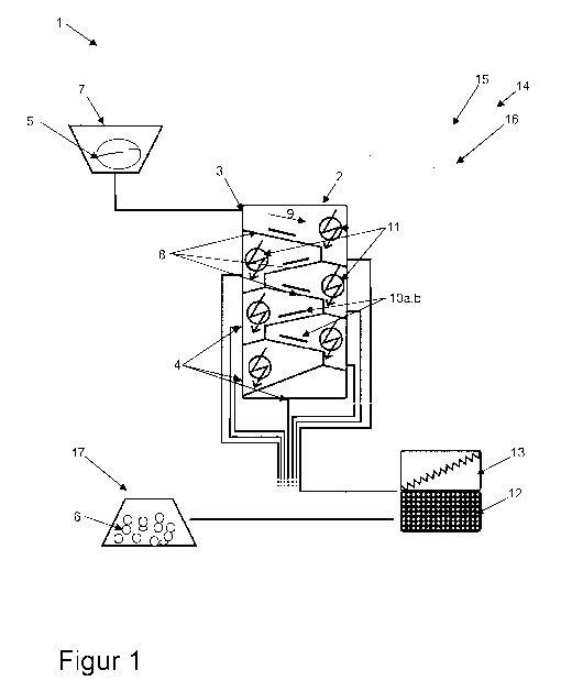
Figure 1 schematically shows a fragmentation system 1. The fragmentation
system 1
comprises a housing 2. The housing 2 is a metal housing. The housing 2 is
constructed
in the form of a silo. The housing 2 has an inlet 3 and a plurality of outlets
4. Via the inlet
3, which here is configured as a hole in the housing 2, material 5 is
introduced into the
housing 2. Fragmented material 6 is removed from the housing 2 via the outlets
4. In
each case different degrees of fragmentation of the fragmented material 6 are
extracted
via the plurality of outlets 4. The fragmentation system 1 is connected to the
material
store 7.
The material store 7 is embodied as a bunker or as a silo. The material 5 can
be stored
in the material store 7 until fragmentation. The material 5 here is a coarse
material, and
comprises blocks and stone-shaped elements. Here the material is concrete that
is
intended to be cleaned up and fragmented. The material store 7 is connected to
the inlet
3 by means of a line in order to bring the material 5 from the material store
into the
housing 2.
A transport path 8 is provided in the housing 2. The transport path 8 leads
from the inlet
3 to the outlets 4. The transport path 8 is embodied here in a rail-type
fashion. The
material 5 is transported along the transport path 8 in a transport direction
9. The
transport path 8 is embodied as a sequence of inclined planes sloping
downward. In
particular, the transport path 8 is embodied as a zigzag inclined plane
sloping downward.
The gradient of the transport path 8 and/or of sections of the transport path
8 is settable
in a manner that is not illustrated. The slope angle of the transport path is
preferably
settable to be between 20 and 80 degrees relative to the horizontal. The
conveying
speed of the material along the transport path 8 is settable and/or variable
by means of
the setting of the slope angle of the transport path 8.
The transport path 8 has fractionation sections. In each case a first
electrode 10a and a
second electrode 10b are arranged in each of the fractionation sections; in
this respect,
see also figures 2 and 4. The electrodes 10a and 10b form a rail. In this
case, the
distance between the electrodes is less than a respective minimum diameter.
The
minimum diameters are different for the different fractionation sections,
wherein the
minimum diameter and/or the distance between the electrodes in the
fractionation
CA 03098305 2020-10-26
- 18 -
section decrease(s) over the course of the transport path 8. The material 5
and/or
fragments of the material can bear partly on the rails and/or the electrodes
10a and 10b.
The material 5 and/or the fragments of the material can slide and/or be
transported on
the electrodes.
The fragmentation system comprises a plurality of high-voltage pulse sources
11,
wherein each of the high-voltage pulse sources 11 comprises in each case one
of the
first electrodes 10a and one of the second electrodes 10b. The high-voltage
pulse
sources 11 are configured to generate a high-voltage discharge in a discharge
chamber
by means of the electrodes 10a and 10b. Material 5 which is situated on the
transport
path 8 and is situated between the electrodes 10a,b or in the discharge
chamber thereof
is fragmented by means of the high-voltage pulse and/or the high-voltage
discharge. The
high-voltage discharge is effected, if material 5 is situated in the
fractionation section, by
the material 5. A fragmentation of the material 5 corresponds to a comminution
and
especially a substance-specific comminution and/or cleaning up. The high-
voltage pulse
source 11 is configured to generate high-voltage discharges with a voltage of
greater
than 10 kilovolts.
The fragmentation system 1 here comprises six high-voltage pulse sources 11
and
respectively six electrodes 10a and 10b arranged at different locations along
the
transport path 8. The high-voltage pulse sources 11 are operated with
different operating
parameters, in particular voltage, pulse length and/or power. The power and/or
the
voltage of the high-voltage pulse sources 11 decrease(s) over the course of
the
arrangement or in the transport direction 9 from inlet 3 to outlet 4. This is
owing to the
fact, in particular, that a higher power is required for material 5 in the
vicinity of the inlet 3
in order to fragment and/or separate said material, and lower operating
parameters and
powers are sufficient for material 5 and/or material fragments in the vicinity
of the outlet 4
that have already been partly comminuted.
In each case a sieving means 12 and a shaking belt 13 are arranged at the
outlets 4
(here indicated symbolically at a distance from the latter). They serve to
sort the
fragments of the material, for example in such a way that small fragments are
directly
extracted and larger fragments are brought back into the housing 2 or remain
in the
housing 2 and undergo the further fragmentation.
CA 03098305 2020-10-26
- 19 -
The fragmentation system 1 comprises a conveying apparatus 14. The conveying
apparatus 14 comprises a media tank 15. A liquid medium 16, here water, is
arranged in
the media tank 15. The medium 16 is conveyed in a conveying direction by means
of the
conveying apparatus 14. In this case, the medium 16 is fed for example in the
region of
the inlet 3 to the housing and/or to the transport path 8 and is collected at
the outlet 4.
The collected medium 16 is filtered by means of a filter device and pumped
back into the
media tank 15, such that the filtered medium 16 can be conveyed again. The
conveying
apparatus 14, by means of conveying the medium 16 along the transport path 8,
serves
to support the transport of the material 5 along the transport path 8. By way
of example,
the transport speed of the material 5 along the transport path 8 is settable
by means of a
setting of the conveying rate of the medium 16.
The fragmented material 6 is collected and stored in a collecting container
17. In
particular, sieved fragmented material 6 is collected and stored in the
collecting container
17. The fragmented material 6 is a comminuted and preferably size- and/or type-
purified
and/or separated material 5.
Figure 2 symbolically shows a segment of a transport path 8, material 5 being
transported in the transport direction 9. The transport path 8 has a plurality
of
fractionation sections 18. The transport path 8 and/or the fractionation
sections 18 are/is
embodied in a rail-type fashion, for example as top-hat rails. In each case a
first
electrode 10a and a second electrode 10b are arranged along the fractionation
sections
18. In this exemplary embodiment, the first electrode 10a and the second
electrode 10b
are arranged parallel to one another. The electrodes 10a and 10b delimit the
transport
path 8 in terms of width. The electrodes 10a and 10b each have a longitudinal
extent,
wherein the longitudinal extent is in particular greater than 10 centimeters
and is
especially greater than 100 centimeters.
The first electrode 10a preferably forms a cathode, with the second electrode
10b
forming an anode. By means of the high-voltage pulse source 11 a high-voltage
pulse
19a, 19b and 19c is able to generated as a high-voltage discharge (symbolized
as an
arrow). The electrodes 10a and 10b in the different fractionation sections 18
are
operated in each case with different operating parameters of the high-voltage
pulse
source 11. In this regard, the high-voltage pulse 19a is a stronger pulse than
the high-
voltage pulse 19b, with the high-voltage pulse 19b being a stronger pulse than
the high-
CA 03098305 2020-10-26
- 20 -
voltage pulse 19c. A stronger pulse means, in particular, that the voltage is
greater
and/or that the power is greater. While the material 5 before the beginning of
the first
fractionation section 18 has a first diameter, the partly fragmented material
between the
first fractionation section and the second fractionation section has a smaller
diameter.
Fragments which arise as a result of the first high-voltage pulse 19a, and
have a
diameter smaller than the minimum diameter fall through the rails and/or
electrodes 10a
and 10b, such that they do not pass into the region of the second high-voltage
pulse 10b.
The same applies analogously to fragments which arise as a result of the
second high-
voltage pulse 19b. Fragmented material 6 having a diameter smaller than the
minimum
diameter is present after the last high-voltage pulse.
Figure 3 shows a further symbolic exemplary embodiment of a transport path 8
for
material transport in the transport direction 9. The transport path 8 is once
again
embodied in a rail-type fashion. The high-voltage pulse sources 11 once again
have in
each case a first electrode 10a and a second electrode 10b. In this exemplary
embodiment, the electrodes 10a and 10b are arranged perpendicularly to the
transport
direction 9. The electrodes 10a and 10b are embodied as rollers that are
rotatable about
their longitudinal axis. The roller-type electrodes 10a and 10b are configured
for
supporting the material transport. Between the electrodes 10a and 10b, in each
case a
high-voltage pulse 19 is able to be generated by means of the high-voltage
pulse source
11, wherein the high-voltage pulse 19 is directed in the same direction as the
transport
direction 9. Between the electrodes 10a and 10b, material comminution is
possible in
each case by means of the high-voltage pulse 19.
Figure 4 shows a further symbolic exemplary embodiment of a transport path 8
for
material transport in the transport direction 9. The high-voltage pulse
sources 11 once
again in each case have a first electrode 10a and a second electrode 10b. The
electrodes 10a and 10b here are arranged in the same direction as the
transport
direction 9. However, the electrodes 10a and 10b of a high-voltage pulse
source 11 are
not arranged parallel to the transport path 8, but rather form an angle with
the transport
direction 9. The first electrode 10a and the second electrode 10b are each
arranged in a
v-shaped fashion. The distance between the first electrode 10a and the second
electrode
10b, in particular in the constriction region, decreases in the course of the
transport path
8 in the transport direction 9. In this regard, the electrodes 10a and 10b can
form a
transport retention at their constriction, such that in particular excessively
large material
CA 03098305 2020-10-26
- 21 -
fragments are retained. The high-voltage pulse 19 is perpendicular or angled
with
respect to the transport direction 9 in a manner similar to figure 2.
CA 03098305 2020-10-26
- 22 -
List of reference signs
1 Fragmentation system
2 Housing
3 Feed
4 Outlet
5 Material
6 Material
7 Material store
8 Transport path
9 Transport direction
10a,b Electrodes
11 High-voltage pulse sources
12 Sieving means
13 Shaking belt
14 Conveying apparatus
15 Media tank
16 Medium
17 Collecting container
18 Fractionation section
19a-19c High-voltage pulse