Note: Descriptions are shown in the official language in which they were submitted.
CA 03098808 2020-10-29
WO 2019/215664 PCT/IB2019/053831
BINDER JETTING AND SUPERSOLIDUS SINTERING OF FERROUS
POWDER METAL COMPONENTS
BACKGROUND
Cross Reference to Related Applications
[0001] The subject application claims priority to U.S. Provisional Patent
Application No.
62/669,450, filed May 10, 2018, the subject matter of which is incorporated
herein by reference in
its entirety.
Field of the Invention
[0002] Various embodiments relate generally to additive manufacturing of
metal parts, and
more particularly to binder jet additive manufacturing of metal parts.
Description of Related Art
[0003] Processes for Additive Manufacturing of metallic parts have been
developed for the
fabrication of complex geometries in a variety of materials. Technologies such
as Selective Laser
Melting (SLM) and Electron Beam Melting (EBM) of particulate metals, typically
produced by Gas
Atomisation (GA), are known. Spherical GA powder grades are expensive and have
found initial
application in high value markets such as Aerospace and Medical Devices.
[0004] The Binder Jetting Additive Manufacturing (BJAM) process is also
known for
prototyping of polymer materials and for the production of sand cores for the
casting industry.
Metallic components are also produced by BJAM, at low sintered densities,
requiring infiltration of
parts after sintering. Slurry pump impellers are an example of application of
this technology.
SUMMARY
[0005] Water Atomized (WA) grades of iron have been used for BJAM
processes, but may
require the additional expense of post-printing infiltration alloys to achieve
high densities. In
addition, final properties are limited to the given the microstructure and
densities produced.
[0006] Highly wear resistant components in industrial and mining sector
applications, such
as slurry pump rotors and drill sections, are conventionally cast or machined
from forgings. These
alloys necessarily have very high hardness, for example 50-65EIRc, and are
difficult to machine. It
is not easy to design complex features for manufacturability reasons.
Accordingly, one or more
1
CA 03098808 2020-10-29
WO 2019/215664 PCT/IB2019/053831
non-limiting embodiments utilize BJAM and sintering to facilitate the
manufacture of complex
shapes, with good wear resistant microstructures and high hardness levels.
According to various of
these embodiments, the design freedom and material properties offer advantages
over conventional
processing.
[0007] Additive Manufacturing typically requires expensive specialized
iron powders (e.g.,
gas atomized iron powders). In contrast, one or more non-limiting embodiments
use readily
available low cost water atomized grades.
[0008] One or more non-limiting embodiments provides a method of
manufacturing a
metallic component by BJAM printing a powder blend of water atomized base iron
powder and a at
least one master ferroalloy powder to form a printed part, and super solidus
sintering the printed
part to form the metallic component.
[0009] According to one or more of these embodiments, the method also
includes, before
said printing, blending the water atomized base iron powder with the at least
one master ferroalloy
powder to form the powder blend.
[0010] According to one or more of these embodiments, the water atomized
base iron
powder comprises pure or prealloyed grade iron powder.
[0011] According to one or more of these embodiments, the sintering
densifies the metallic
component.
[0012] According to one or more of these embodiments, the metallic
component comprises
a high strength metallic component.
[0013] According to one or more of these embodiments, the ferroalloy
comprises a
transition element.
[0014] According to one or more of these embodiments, the transition
element comprises
Cr, Mn, Mo, V, W, Ni, or Cu.
[0015] According to one or more of these embodiments, the at least one
master ferroalloy
powder comprises between 5 and 10 wt% carbon.
[0016] According to one or more of these embodiments, the at least one
master ferroalloy
powder has a D50 particle size of less than 45 um.
2
CA 03098808 2020-10-29
WO 2019/215664 PCT/IB2019/053831
[0017] According to one or more of these embodiments, the water atomized
base iron
powder has a D50 particle size of less than 40 um.
[0018] According to one or more of these embodiments, the water atomized
base iron
powder has a D50 particle size of between 70 and 130um.
[0019] According to one or more of these embodiments, the powder blend has
a total alloy
content of between 15 and 35 wt %.
[0020] According to one or more of these embodiments, the powder blend has
a carbon
content of between 2 and 5 wt %.
[0021] According to one or more of these embodiments, said printing
comprises curing and
depowdering to form the printed part.
[0022] According to one or more of these embodiments, the printed part has
a porosity of
40-60% before said sintering, and said sintering reduces the porosity to less
than 10% in the
metallic component.
[0023] According to one or more of these embodiments, the metallic
component has a
porosity of less than 10%.
[0024] According to one or more of these embodiments, said sintering
occurs at
temperatures between 1100 and 1400 C.
[0025] According to one or more of these embodiments, said sintering
causes linearly
shrinks the printed part by 15-25%.
[0026] According to one or more of these embodiments, a microstructure of
the metallic
component contains carbide phase portions embedded in a matrix, wherein the
matrix is softer than
the carbide phase portions.
[0027] According to one or more of these embodiments, the carbide phase
portions have a
micro hardness of 1000-1700 HVO.1.
[0028] According to one or more of these embodiments, the matrix has a
micro hardness of
250-800 HVO.1.
[0029] According to one or more of these embodiments, upon completion of
said sintering,
the metallic component has a hardness of 30-50 EIRC.
3
CA 03098808 2020-10-29
WO 2019/215664 PCT/IB2019/053831
[0030] According to one or more of these embodiments, the method also
includes, after said
sintering, heat treating the metallic component, wherein said heat treating
increases a hardness of
the metallic component.
[0031] According to one or more of these embodiments, the metallic
component contains
carbide phase portions embedded in a martensitic matrix.
[0032] According to one or more of these embodiments, after said heat
treating, the metallic
component has a hardness of at least 50 EIRC.
[0033] According to one or more of these embodiments, after said heat
treating, the metallic
component has a hardness of 55-65 EIRC.
[0034] According to one or more of these embodiments, the carbide phase
portions have a
micro hardness of 1000-1700 HVO.1.
[0035] According to one or more of these embodiments, the matrix has a
micro hardness of
600-800 HVO.1.
[0036] According to one or more of these embodiments, after said heat
treating, the metallic
component has a wear resistance so as to have a volume loss of less than or
equal to 100 mm3
according to ASTM G65-10 procedure A.
[0037] One or more embodiments provide a metallic component manufactured
by: binder jet
additive manufacture printing a powder blend to form a printed part; and super
solidus sintering the
printed part to form the metallic component. The powder blend comprises a
blend of water
atomized base iron powder and at least one master ferroalloy powder.
[0038] One or more embodiments facilitates the manufacture of complexly
shaped ferrous
alloy components to high densities, hardnesses, and toughnesses without the
need for secondary
operations to achieve the net desired component shape and size.
[0039] According to various embodiments, the BJAM printing process
facilitates new low
volume markets for complex, tough, hard components.
[0040] Components manufactured according to one or more of these
embodiments may
include drill parts, slurry pumps, etc.
4
CA 03098808 2020-10-29
WO 2019/215664 PCT/IB2019/053831
[0041] One or more of these and/or other aspects of various embodiments of
the present
invention, as well as the methods of operation and functions of the related
elements of structure and
the combination of parts and economies of manufacture, will become more
apparent upon
consideration of the following description and the appended claims with
reference to the
accompanying drawings, all of which form a part of this specification, wherein
like reference
numerals designate corresponding parts in the various figures. It should be
appreciated that
structural features shown or described in any one embodiment herein can be
used in other
embodiments as well. As used in the specification and in the claims, the
singular form of "a", "an",
and "the" include plural referents unless the context clearly dictates
otherwise.
[0042] All closed-ended (e.g., between A and B) and open-ended (greater
than C) ranges of
values disclosed herein explicitly include all ranges that fall within or nest
within such ranges. For
example, a disclosed range of 1-10 is understood as also disclosing, among
other ranges, 2-10, 1-9,
3-9, etc. Similarly, where multiple parameters (e.g., parameter C, parameter
D) are separately
disclosed as having ranges, the embodiments disclosed herein explicitly
include combinations of
any value within the disclosed range of one parameter (e.g., parameter C) with
any value within the
disclosed range of any other parameter (e.g., parameter D).
BRIEF DESCRIPTION OF THE DRAWINGS
[0043] For a better understanding of various embodiments as well as other
objects and
further features thereof, reference is made to the following description which
is to be used in
conjunction with the accompanying drawings, where:
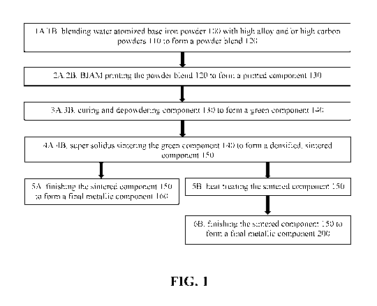
[0044] FIG. 1 is a flowchart illustrating various methods of manufacturing
metallic
components according to alternative embodiments.
[0045] FIG. 2 is an illustrative Fe-C phase diagram.
[0046] FIG. 3 is a perspective drawing of a metallic component made in
accordance with
one or more of the manufacturing methods shown in FIG. 1.
CA 03098808 2020-10-29
WO 2019/215664 PCT/IB2019/053831
DETAILED DESCRIPTION OF EXEMPLARY EMBODIMENTS
[0047] FIG. 1 is a flowchart illustrating various methods of manufacturing
metallic
components according to alternative embodiments. Steps 1A-5A provide
manufacturing steps for a
non-heat treated component 160, while steps 1B-6B provide manufacturing steps
for a heat-treated
component 200.
[0048] At step 1A/1B, base iron powder and/or a prealloyed base iron
powder 100 is
blended with a master alloy powder 110 to form a powder blend 120.
[0049] According to various embodiments, the base iron powder 100
comprises at least 10,
20, 30, 40, 50, 60, 70, 80, 90, 95, and/or 100% water atomized (WA) elemental
iron powder.
According to various embodiments, the iron powder 100 comprises a standard,
low-cost, WA iron
powder. According to various embodiments, the WA iron powder 100 has a D40,
D45, D50, D55,
D60, D65, D70, D75, and/or D80 particle size of (a) less than 150, 140, 130,
125, 120, 115, 110,
105, 100, 95, 90, 85, 80, 70, 65, 60, 55, 50, 45, 40, 35, and/or 30 um, (b)
more than 20, 25, 30, 35,
40, 45, 50, 55, 60, 65, 70, 75, 80, 85, 90, 95, and/or 100 um, and/or (c)
between any two such values
(e.g., a D50 particle size of between 20 and 150 um, 25 and 40 um, and/or 90
and 110 um; a D60
particle size of between 20 and 150 um, 25 and 40 um, and/or 90 and 110 um).
[0050] According to various embodiments, the master alloy powder 110
comprises at least
one ferroalloy powder that includes ferrous powder with a high alloy and high
carbon content.
According to various embodiments, the alloy material of the master alloy
powder 110 comprises
one or more transition elements typically used in steel and cast iron
metallurgy, including but not
limited to, Cr, Mn, Mo, V, W, Ni, and/or Cu. Thus, the master alloy powder 110
may comprise one
or more ferroalloys such as ferromanganese (FeMn), ferrochromium (FeCr),
ferrovanadium (FeV),
and/or ferromolybdenum (FeMo). According to various embodiments, the master
alloy powder 110
comprises a mixture of one or more of these ferroalloys (including any and all
combinations of
these ferroalloys). For example, according to various embodiments, the master
alloy powder 110
comprises a mixture of the FeMn Powder Blend (discussed below) and FeCr Powder
Blend
(discussed below).
[0051] According to various embodiments, the master alloy powder 110 has a
carbon
content of (a) at least 2, 3,4, 5, 6, 7, 8, 9, and/or 10 wt %, (b) less than
14, 13, 12, 11, 10, 9, 8, 7, 6,
5, 4, 3, 2, and/or 1 wt %, and/or (c) between any two such values (e.g.,
between 2 and 14 wt %,
6
CA 03098808 2020-10-29
WO 2019/215664 PCT/IB2019/053831
between 5 and 10 wt%). According to various embodiments, the use of
ferroalloys with high
carbon content facilitates effective BJAM printing of the alloy powder 110 so
as to facilitate BJAM
introduction of the included carbon into the printed component 130. The
ferroalloys thus function
as an effective BJAM printable carrier for carbon so as to increase the carbon
content of the printed
component 130.
[0052] According to various embodiments, the master alloy powder 110 has a
D40, D50,
D60, D70, and/or D80 particle size of (a) less than 70, 65, 60, 55, 50, 45,
40, 35, 30, 25, 20, 19, 18,
17, 16, 15, 14, 13, 12, 11, 10, and/or 9 um, (b) more than 5, 6, 7, 8, 9, 10,
15, 20, 25, and/or 30 um,
and/or (c) between any two such values (e.g., between 5 and 70 um, between 5
and 45 um, between
8 and 12 um).
[0053] According to one embodiment, the master alloy powder 110 comprises
6.53% C,
75.3% Mn, 1.5% Si, 0.025% S, and 0.18% P, with a D50 of 8.1 um and a D97 of
20.76 um.
Hereinafter, this master alloy powder is referred to as FeMn Powder Blend
(despite the fact that this
powder comprises additional components).
[0054] According to an alternative embodiment, the master alloy powder 110
comprises
8.7% C, 60.4% Cr, 2.7 % Si, 0.03 % S, and 0.03 % P, with a D50 of 8.2 um and a
D97 of 22.18 um.
Hereinafter, this master alloy powder is referred to as FeCr Powder Blend
(despite the fact that this
powder comprises additional components).
[0055] According to an alternative embodiment, the master alloy powder 110
comprises
50% FeCr Powder Blend and 50% FeMn Powder Blend. According to an alternative
embodiment,
the master alloy powder 110 comprises about 97% FeCr Powder Blend and about 3%
FeMn Powder
Blend. However, any ratio of such Powder Blends may be used for the master
alloy powder 110,
e.g., at least 1, 2, 3, 4, 5, 10, 15, 20, 30, 40, 50, 60, 70, 80, 85, 90, 95,
96, 97, 98, and/or 99% FeCr
Powder Blend, and/or at least 1, 2, 3, 4, 5, 10, 15, 20, 30, 40, 50, 60, 70,
80, 85, 90, 95, 96, 97, 98,
and/or 99% FeMn Powder Blend.
[0056] According to various embodiments, introduction of carbon via the
master alloy
powder 110, rather than via elemental carbon (e.g., graphite), promotes more
even mixing and
distribution of the carbon content within the powder blend 120 (and the
resulting printed component
130).
7
CA 03098808 2020-10-29
WO 2019/215664 PCT/IB2019/053831
[0057] According to various embodiments, the base iron powder 100 may be
blended with
the master alloy powder 110 in a variety of combinations to tailor the powder
blend 120 as
appropriate to achieve specific application property requirements. According
to various
embodiments, base iron powder 100 content of the powder blend 120 is (a) at
least 45, 50, 55, 60,
65, 70, 75, 80, and/or 85%, (b) less than 95, 90, 85, 80, 75, 70, 65, 60, 55,
50, 45, 40, and/or 35%,
and/or (c) between any two such values (e.g., between 45 and 95%, between 55
and 65%, between
75 and 85%). According to various embodiments, the master alloy powder 110
content of the
powder blend 120 is (a) less than 65, 60, 55, 50, 45, 40, 35, 30, 25, 20,
and/or 15%, (b) greater than
5, 10, 15, 20, 25, 30, 35, 40, 45, 50, 55, 60, and/or 65 %, and/or (c) between
any two such values
(e.g., between 5 and 65%, between 35 and 45%, between 25 and 35%).
[0058] According to various embodiments, the powder blend 120 has a total
non-Fe alloy
content (i.e., the cumulative content of the non-iron components of the powder
blend 120 (e.g.,
including Cr, Mn, Mo, C, etc.)) of at least 5, 10, 15, 20, 25 wt %, less than
50, 45, 40, 35, 30 wt %,
and/or between any two such values (e.g., between 5 and 50 wt %, between 10
and 45 wt %,
between 15 and 35 wt %). According to various embodiments, the total iron
content of the powder
blend 120 may comprise (a) at least 50, 55, 60, 65, 70, 75, 80, 85, 90, and/or
95% Fe, (b) less than
5, 10, 15, 20, and/or 25% Fe, and/or (c) any value between any two such upper
and lower values
(e.g., between 50 and 95 % Fe, between 55 and 90 % Fe, between 65 and 85 %
Fe).
[0059] According to various embodiments, the blend powder 120 has a carbon
content of (a)
at least 1, 2, 2.5, 3, 3.5, and/or 4 wt %, (b) less than 6, 5.5, 5, 4.5, 4,
3.5, 3, 2.5, 2, and/or 1 wt %,
and/or (c) between any two such values (e.g., between 2 and 5 wt %, between 2
and 3.5 wt%).
[0060] According to one embodiment (hereinafter referred to as blend code
E2132), the
blended powder 120 comprises about 20% FeCr alloy Powder (e.g., 28% Fe, 60%
Cr, 9% C), 20%
FeMn alloy Powder Blend (e.g., 17% Fe, 75% Mn, 6%C), and about 60% base iron
powder 100.
According to various embodiments, after sintering, E2132 comprises about 3.05
% C, 15 % Mn, 12
% Cr, 0.84 % Si, and about 70 % Fe.
[0061] According to an alternative embodiment (hereinafter referred to as
blend code
E2138), the blend powder 120 comprises about 30% FeCr Powder, 1% FeMn Powder,
and about
69% base iron powder 100. According to various embodiments, after sintering,
E2138 comprises
about 2.7 % C, 0.75 % Mn, 18.1 % Cr, 0.83 % Si, and about 78 % Fe.
8
CA 03098808 2020-10-29
WO 2019/215664 PCT/IB2019/053831
[0062] According to various embodiments, the powder blend 120 comprises 11-
30% Cr, 0-
2.5% Ni., 0-18% Mn, 0-3% Mo, 0-1.2% Cu, 2-5% C, 0-3% V, and the balance being
Fe and
unavoidable impurities.
[0063] At step 2A/2B, the blend powder 120 is BJAM printed into a printed
3D component
130 made up of a plurality of layers bound together to form the 3D component.
According to
various embodiments, carbon is introduced into the component 130 via the
carbon content of the
master alloy powder 110, rather than through elemental carbon (e.g.,
graphite). According to
various embodiments, this avoids the difficult process of BJAM printing
elemental carbon (e.g.,
graphite) and/or avoids having to modify the WA iron powder to have a higher
carbon content. It
would be difficult or impossible to simply blend elemental carbon into the
powder to be printed
because elemental carbon (graphite) is very fine (e.g., 5-15 um) and dusty and
would not blend well
or flow and spread. According to various embodiments, adding carbon as a
master alloy form
allows blending and spreading in the powder bed.
[0064] At step 3A/3B, the printed component 130 is cured and depowdered to
form a green
component 140. According to various embodiments a density of the green
component 140 is (a) at
least 30%, 35%, 40%, 45%, 50%, 55%, and/or 60%, (b) less than 65%, 60%, 55%,
50%, 45%,
and/or 40%, and/or (c) between any two such values (e.g., between 30 and 65%,
between 30 and
60%, between 35 and 55%, between 40 and 60%). According to various
embodiments, a density of
the green component 140 is a function of the particle size distribution of the
powder blend 120, and
is relatively close to an apparent density of the powder blend 120 (e.g.,
ranging from 3 g/cc to 4
g/cc according to various non-limiting embodiments).
[0065] At step 4A/4B, the green component 140 is super solidus sintered to
form a sintered
component 150. Super solidus sintering results in a combination of liquid and
solid phases being
present at different percentages. The liquid phase material helps to shrink
and densify the
component, while the solid phase material helps to maintain the component's
shape and avoid
slumping.
[0066] According to various embodiments, the super solidus sintering
occurs at
temperatures between 1100 and 1400 C. According to various embodiments, the
sintering
temperature is selected to correspond to the super solidus temperature of
constituents of the
component 140 (i.e., the super solidus range based on the phase diagram of the
component 140). As
9
CA 03098808 2020-10-29
WO 2019/215664 PCT/IB2019/053831
the sintering temperature increases, carbon diffuses until locally it forms a
liquid phase, which
promotes interdiffusion of alloy elements with iron. At the top temperature,
there remains a
percentage of liquid phase which accelerates further particle consolidation
and sintering, pore
rounding, densification, and homogenization of carbon and alloys.
[0067] The sintering temperature may be balanced to increase liquid phase
material, while
maintaining sufficient solid phase material to maintain the component's shape.
According to one or
more embodiments, the sintering occurs in the shaded super solidus temperature
zone shown in
FIG. 2. The phase diagram in FIG. 2 is for Fe-C only, and is provided for
illustration purposes
only. The addition of alloys (e.g., transition metals) will modify the phase
diagram of the actual
alloy powder.
[0068] According to various embodiments, the sintering shrinks and
densifies the green
component 140 so as to create a sintered component 150 with a density of (a)
at least 80, 81, 82, 83,
84, 85, 86, 87, 88, 89, 90, 91, and/or 92%, (b) less than 100, 99, 98, 97, 96,
95, 94, 93, and/or (c)
between any two such values (e.g., between 80 and 99%, between 85 and 95%,
between 90 and
95%). According to various embodiments, such density is achieved without post-
sintering
infiltration of material.
[0069] According to various embodiments, the sintering results in linear
shrinkage of the
green component 150 of (a) at least 15, 16, 17, 18, 19, 20, 21, 22, 23, 24,
25, 26, 27, 28, 29, and/or
30%, (b) less than 40, 35, 34, 33, 32, 31, 30, 29, 28, 27, 26, 25, 24, 23, 22,
21, 20, 19, and/or 18%,
and/or (c) between any two such values (e.g., between 15 and 40%, between 20
and 27 %, between
15 and 25%).
[0070] At step 5A, the sintered metallic component 150 is finished (e.g.,
via machining,
polishing, etc.) to form the non-heat-treated final metallic component 160.
However, according to
various embodiments, the finishing step is omitted, and the sintered metallic
component 150 is the
final metallic component.
[0071] According to various embodiments, the component 160 has a hardness
of (a) at least
25, 30, 35, 40, and/or 45 HRC, (b) less than 55, 50, 45, 40, and/or 35 I-MC,
and/or (c) between any
two such values (e.g., between 25 and 55 FERC, between 30 and 50 FERC, between
35 and 45 I-MC).
[0072] According to various embodiments, the component 160 has a
microstructure that
contains relatively hard carbide phase portions embedded in an austenite
matrix that is softer than
CA 03098808 2020-10-29
WO 2019/215664 PCT/IB2019/053831
the carbide phase portions. According to various embodiments, the component
160 has a good
combination of wear resistance and toughness. According to various
embodiments, the carbide
phase portions have a micro hardness of 1000-1700 HVO.1, and the matrix has a
micro hardness of
250-800 HVO.1 and/or 250-350 HVO.1.
[0073] According to one or more embodiments, the powder blend 120 is
E2132, the
sintering occurs at around 1180 C and results in about 23% linear shrinkage,
the post-sintering
(e.g., non-heat treated) hardness of the component 160 is about 37.0 EIRC, a
micro hardness of the
carbide phase portions is about 1089 HVO.1, and a micro hardness of the matrix
(e.g., austenite) is
about 313 HVO.1, and a Transverse Rupture Strength (TRS) of the component 160
is about 1373
MPa.
[0074] Alternatively, as shown as step 5B, the sintered metallic component
150 may be heat
treated (e.g., hardening, quenching).
[0075] Although not illustrated in FIG. 1, the sintered metallic component
150 may be
finished/machined prior to the heat treatment step 5B. According to various
embodiments, such
finishing/machining is easier to do prior to the heat treatment. The
finishing/machining may be
done to conform the component 150 to the desired shape and tolerances of the
final component 200.
[0076] At step 6B, the heat-treated metallic component is finished to form
a final, heat-
treated metallic component 200. However, according to various embodiments, the
finishing step is
omitted, and the heat-treated metallic component is the final metallic
component.
[0077] According to various embodiments, the component 200 has a
microstructure that
contains hard carbide phase portions embedded in a hard martensitic matrix.
According to various
embodiments, the component has superior wear resistance and high hardness.
According to various
embodiments, the carbide phase portions of the component 200 have a micro
hardness of 1000-1700
HVO.1. According to various embodiments, the matrix of the component 200 has a
micro hardness
of 600-800 HVO.1. According to various embodiments, after said heat treating,
the metallic
component 200 has a wear resistance so as to have a volume loss of less than
or equal to 100 mm3
according to ASTM G65-10 procedure A.
[0078] According to various embodiments, the component 200 has a hardness
of (a) at least
40, 45, 50, 55, and/or 60 EIRC , (b) less than 80, 75, 70, 65, and/or 60 EIRC,
and/or (c) between any
two such values (e.g., between 40 and 80 EIRC, between 50 and 60 EIRC, between
55 and 65 EIRC).
11
CA 03098808 2020-10-29
WO 2019/215664 PCT/IB2019/053831
[0079] According to one or more embodiments, the powder blend 120 is
E2138, the
sintering occurs at around 1300 C and results in a density of about 7.50 g/cc,
the sintered
component 150 is heat treated via neutral hardening, the post-heat-treated
hardness of the
component 200 is about 60 EIRC, a micro hardness of the carbide phase portions
is about 1550
HVO.1, and a micro hardness of the martensitic matrix is about 690 HVO.1.
However, according to
alternative embodiments, the E2138 powder blend 120 may alternatively be used
in a process that
omits a heat treatment step to provide a final metallic component 160 made
from E2138 with
carbide phase embedded in a ferritic/pearlitic matrix.
[0080] Unless otherwise specifically stated, all contents and percentages
are on a weight
basis. Thus, 5% means 5 weight (wt) %.
[0081] According to various embodiments, the components 150, 160, 200 may
comprise
components of a rock drill (e.g., a rifle nut 210 (see FIG. 3), a splined nut,
a rifle piston, a chuck,
etc.), including, without limitation, any of the components of the rock drill
disclosed in U.S. Patent
Nos. 3,055,441 or 2,061,807, the entire contents of both of which are hereby
incorporated by
reference herein. According to various embodiments, the components 150, 160,
200 may comprise
one or more components of a slurry pump (e.g., rotor, vane, impeller, pump
housing, volute),
including, without limitation, any of the components of the slurry pump
disclosed in U.S. Patent
No. 5,797,724, which is hereby incorporated herein in its entirety.
[0082] The foregoing illustrated embodiments are provided to illustrate
the structural and
functional principles of various embodiments and are not intended to be
limiting. To the contrary,
the principles of the present invention are intended to encompass any and all
changes, alterations
and/or substitutions thereof (e.g., any alterations within the spirit and
scope of the following
claims).
12