Note: Descriptions are shown in the official language in which they were submitted.
CA 03099349 2020-11-04
WO 2019/223984
PCT/EP2019/061440
- 1 -
EFF IC IENT SATELLITE STRUCTURE CONCEPT FOR SINGLE OR
STACKING MULTIPLE LAUNCHES
TECHNICAL FIELD OF THE INVENTION
The present invention relates, in general, to the
technical sector of systems for
deploying
spacecraft's/satellites in orbit from launch vehicles and,
more particularly, to an efficient satellite structure
concept and its dedicated launcher interface, suitable for
a single launch, or a stacking multiple launch, from a
single launch vehicle.
STATE OF THE ART
As is known, launch vehicles (also simply known as
launchers) are used to deploy spacecraft's/satellites in a
predetermined orbit around the Earth. To this end, one or
more systems for deploying one or more spacecraft and/or
one or more satellites are typically used, each of which is
generally configured to:
= during launch,
securely and strongly hold down one
or more spacecraft and/or one or more satellites stowed in
an available volume of a launcher; and,
= when the launcher reaches a predefined position in
orbit, deploy (i.e., release) the spacecraft/satellite(s)
in response to a control signal.
CA 03099349 2020-11-04
WO 2019/223984
PCT/EP2019/061440
- 2 -
Some known solutions related to this sector are
provided in US 8,915,472 B2 and US 9,669,948 B2.
In particular, US 8,915,472 B2 concerns a multiple
space vehicle launch system and discloses a launch system
composed of two satellites: a lower one and an upper one.
The lower one is releasably attached to the upper stage of
the launch vehicle by means of a standard ring interface
and again releasably attached to the upper satellite by
means of the same type of standard ring interface. The
lower satellite bears the launch loads induced by the upper
satellite, thereby eliminating the need for additional
support structures (e.g., a dispenser). Both satellites
include a central core structure bearing the main portion
of the launch loads that is connected to the ring
interfaces.
US 9,669,948 B2 relates to a side-by-side dual-launch
spacecraft arrangement and discloses a launch system
composed of two satellites placed side-by-side on a dual-
launch adaptor. Both satellites are releasably attached to
the dual-launch adaptor by means of a standard ring
interface. The dual-launch adaptor is mounted on the last
stage of the launch vehicle by means of a standard ring
interface. Both satellites include a central core structure
bearing the main portion of the launch loads connected to
the ring interface.
CA 03099349 2020-11-04
WO 2019/223984
PCT/EP2019/061440
- 3 -
DESCRIPTION OF THE INVENTION
1. Brief description of the drawings
For a better understanding of the present invention,
preferred embodiments, which are intended purely by way of
non-limiting examples, will now be described with reference
to the attached drawings (all not to scale), where:
= Figure 1 schematically illustrates a satellite
structure concept and a Payload Attaching Fitting (PAF)
according to a preferred, non-limiting embodiment of the
present invention;
= Figure 2 schematically illustrates stacking of three
satellites on a PAF (with a single-tower architecture)
according to a preferred, non-limiting embodiment of the
present invention;
= Figure 3 schematically illustrates four satellites on
a PAF (with a side-by-side architecture) according to a
preferred, non-limiting embodiment of the present
invention;
= Figure 4 schematically illustrates a releasable cup-
cone interface between two adjacent satellites or between
the lower satellite and the PAF (with any architecture)
according to a preferred, non-limiting embodiment of the
present invention;
CA 03099349 2020-11-04
WO 2019/223984
PCT/EP2019/061440
- 4 -
= Figure 5 schematically illustrates a variable number
of electro-actuated separation devices that can be
installed between adjacent satellites or between the lower
satellite and the PAF (with any architecture) according to
a preferred, non-limiting embodiment of the present
invention;
= Figure 6 schematically illustrates a releasable
electrical connector and spring driven pushers installed at
selected cup-cone separation interface according to a
preferred, non-limiting embodiment of the present
invention;
= Figure 7 schematically illustrates a truss structure
architecture concept according to a preferred, non-limiting
embodiment of the present invention;
= Figure 8 schematically illustrates stacking of two
satellites on a PAF (with single-tower architecture)
according to a preferred, non-limiting embodiment of the
present invention;
= Figure 9 schematically illustrates stacking of two
satellites on a PAF (with side-by-side architecture)
according to a preferred, non-limiting embodiment of the
present invention;
= Figure 10 schematically illustrates a releasable
interface between a generic satellite (having variable
cross-section dimensions) and the same PAF according to
CA 03099349 2020-11-04
WO 2019/223984
PCT/EP2019/061440
- 5 -
non-limiting examples of the present invention; and
= Figure 11 schematically illustrates the lower part of
the separation system mounted on a frame that can be
mounted and dismounted by means of a bolted interface on a
PAF or on the lower satellite of the stack according to
non-limiting examples of the present invention.
2. Theoretic basis of the invention
The concept of the present invention is based on the
following considerations. From a structural mechanics point
of view, the spacecraft can be simplified as a cantilever
beam subject to inertial loads induced by the launcher. It
is evident that the external satellite structures are more
effective for bearing the launch loads due to their higher
area moment of inertia opposed to central core structures
(with cross-section dimension lower than external satellite
structures cross-section dimension). The area moment of
inertia is a key factor in structural stiffness and
strength.
The typical external surfaces of a satellite are plane,
to provide the simplest and most efficient support for
internal electronic units and external thermal radiators.
This implies the need to introduce a dedicated launcher
interface that can provide the load transition mean from
the corners among the plane surfaces and the launch vehicle
CA 03099349 2020-11-04
WO 2019/223984
PCT/EP2019/061440
- 6 -
bolted interface.
In summary, the present invention allows a more
complete exploitation of the mass capability of the launch
vehicle in conjunction with a dedicated launcher interface
that is relatively light and compact and remains connected
to the launch vehicle after satellite separation with Earth
re-entry or graveyard disposal of itself.
3. Satellite structural concept
The satellite structural concept according to the
present invention comprises an external load-bearing
structure, typically with square or rectangular base (but
also other shapes may be conveniently used).
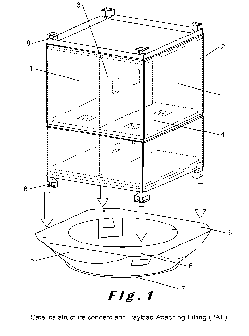
With reference to Figure 1, the structure includes
external vertical plane panels 1 connected by vertical
beams 2. The external vertical plane panels 1 can be
realized in any material typically used for satellite
manufacturing (i.e., aluminium, aluminium sandwich, carbon
fiber reinforced thermoplastic (CFRP) monocoque, CFRP
sandwich, titanium, etc., or a combination thereof).
The vertical panels 1 are connected by means of four
(or even more) corner beams 2. The corner beams 2 may have
any cross-section (typically, square, rectangular or
circular) and can be realized in any material typically
used for satellite manufacturing. The corner beams 2 have
CA 03099349 2020-11-04
WO 2019/223984
PCT/EP2019/061440
- 7 -
releasable interfaces at their bottom and upper edges 8.
Internal vertical shear panels 3 and horizontal platform
panels 4 may also be used for structural or equipment
accommodation convenience.
4. Bottom transition structure
Always with reference to Figure 1, a bottom transition
structure (or Payload Attaching Fitting - PAF) 5 completes
the concept. In the upper part of the PAF 5, there are a
discrete number of releasable interfaces 6 with each corner
beam 2 of the satellite structure and in the lower part
there is a bolted interface 7 with the upper stage of the
launch vehicle (not shown in Figure 1).
With reference to Figure 10, various satellite cross-
section dimensions 14 can be accommodated on the same PAF
15 with no need to redesign the latter. This is possible by
changing the terminal angle of the vertical beams 16.
With reference to Figure 11, in order to facilitate
transport, interface fit check and separation testing of
satellites, the lower part of the separation system is
mounted on a frame 17 that can be mounted and dismounted by
means of a bolted interface on the PAF 18, or on the lower
satellite of the stack 19.
5. Stacking of the satellites
CA 03099349 2020-11-04
WO 2019/223984
PCT/EP2019/061440
- 8 -
The stacking of the satellites can be realized as a
single tower as shown in Figure 2, mounted on the relevant
PAF, or as a double tower, i.e., two towers arranged side-
by-side, as shown in Figure 3, mounted on the relevant PAF
20 designed to accommodate the two towers of satellites.
The assembly architecture depends on the available fairing
volume and mass capacity of the selected launcher.
The releasable interfaces between stacked satellites
and between the lower satellite(s) and the PAF are
identical. These interfaces conveniently include:
= with reference to Figure 4, mechanical interfaces
including at least three cup-cone interfaces 10 connected
at the edge of each corner beam 2;
= with reference to Figure 6, electrical harness
interfaces 21 to provide communication with the launch
vehicle and the ground support equipment; the releasable
interfaces being equipped with brackets for electrical
connectors;
= micro-switches for satellite separation detection;
= again with reference to Figure 6, systems 22 for
ensuring spacecraft separation, typically spring driven
separation pushers at selected separation interfaces to
impart the necessary initial kinetic energy to the
satellites after separation.
Again with reference to Figure 4, the cup-cone
CA 03099349 2020-11-04
WO 2019/223984
PCT/EP2019/061440
- 9 -
interface 10 is capable to carry all local loads with
exception of the axial traction load that is carried by the
electro-actuated separation device(s) (e.g., NEA, Pyro-
bolt, etc.).
With reference to Figure 5, the lowest connection of
the stacking (PAF-lower satellite) can use all the three
(or more) separation devices 11. The upper connections 12
can use a lower number of separation devices due to the
lower load levels.
The external planar panels 1 may incorporate the corner
beams 2; this is foreseeable if additive manufacturing
technologies are used.
With reference to Figure 7, the basic structural
concept is equivalent to the known Truss Structure
architecture made just of vertical and diagonal beams.
Nevertheless, satellite external structures cannot be open
with diagonal beams 13 as they are planar to accommodate
the electronic equipment, act as thermal radiators and
provide a close envelope for radiation shielding. This
means that the structural reinforcement function, exerted
by the diagonal beams, is performed by the sandwich panels.
These panels, for structural optimisation reasons, may
conveniently include reinforcement embedded structures or
skin thickness reinforcements 23.
CA 03099349 2020-11-04
WO 2019/223984
PCT/EP2019/061440
- 10 -
6. Two preferred, non-limiting embodiments of the
invention
Two preferred, non-limiting embodiments of the inventions
are:
1) with reference to Figure 8, a single-tower
architecture with the stacking of two identical satellites
mounted on the dedicated PAF;
2) with reference to Figure 9, a side-by-side
architecture with two identical satellites mounted on the
dedicated PAF.
7. Main technical advantages of the invention with
respect to similar existing concepts
a) In principle, as explained in the paragraph 2
"Theoretic basis of the invention", the present invention
is more efficient from a structural viewpoint with respect
to the existing solutions (i.e., a certain stiffness
performance level can be achieved with a lower structural
mass).
b) The structural efficiency can be used in favour of
an all-aluminium structure with higher performances
concerning radiation shielding and cost reduction with
respect to CFRP structures.
c) The internal volume of the satellite is fully
available for equipment accommodation, whereas this is not
CA 03099349 2020-11-04
WO 2019/223984
PCT/EP2019/061440
- 11 -
the case of a satellite with a large and long internal
structural tube.
d) The top and the bottom platforms of the satellite
are completely available for equipment accommodation,
whereas (again) this is not the case of a satellite with a
large and long internal structural tube.
e) The complexity of the present invention is limited
to the compact PAF structure and interfaces and not to the
large and long internal structural tubes.
f) The cost of a limited number of pyros/NEA separation
bolts is competitive with respect to the cost of two or
more clamp-band systems.
g) The separable interface can be more robust at the
base of the satellite stacking, where the mechanical loads
are higher, and less robust for the other separable
interfaces of the stacking.
In conclusion, it is worth noting that the present
invention, which relates to a satellite structural concept
with a mainly external load-carrying structure and its
dedicated launcher interface, allows an efficient
exploitation of the launch vehicle mass capability and
satellite internal volume. This concept according to the
present invention can be advantageously used for any space
mission/orbit/launcher if deemed convenient.