Note: Descriptions are shown in the official language in which they were submitted.
CA 03099425 2020-11-04
WO 2019/215511 PCT/IB2019/000578
1
APPARATUS AND METHOD FOR DENTAL CLAMPING
CROSS-REFERENCE
[0001] This application claims the benefit of U.S. Provisional Patent
Application No.
62/669,934, filed on May 10, 2018, U.S Provisional Patent Application No.
62/727,390, filed on
September 5, 2018, U.S. Provisional Patent Application No. 62/755,961, filed
on November 5,
2018, U.S. Provisional Patent Application No. 62/755,989, filed on November 5,
2018, and U.S.
Provisional Patent Application No. 62/830,951, filed on April 8, 2019, each of
which is entirely
incorporated herein by reference.
BACKGROUND
[0002] Although advances have been made in recent years for the treatment of
specific dental
diseases, the actual delivery of dental treatment remains a manually intensive
process.
Accordingly, there is a need for methodology for automating dental treatment.
SUMMARY
[0003] The existing dental treatment apparatuses or systems are unable to
achieve automated
dental treatment, e.g., automated tooth cutting. The existing apparatuses or
systems rely on vision
systems (e.g., human vision, real-time images of the teeth) for carrying out
dental treatment, and
there are major technical challenge(s) and regulatory risk(s) associated with
automation of the
vision-based dental treatment methods. Further, automation attempts utilizing
expensive robotic
arms can put the price point to above $100K for the dental treatment system(s)
and are unlikely
to be approved for full automation by the FDA due to the large working
envelope in which its
arms could cause damage. Thus, there is an urgent and unmet need for
automating dental
treatment with cost-effective, safe, and reliable apparatuses and systems.
Also, one of the
applications herein is to cut the teeth for crowns (cutting teeth themselves),
not for dental drilling
in surgery (drilling bore holes into bone for dental implants).The present
disclosure relates to
apparatuses, systems and methods for automating dental treatment.
[0004] In some embodiments, the present disclosure herein includes a tooth
clamp which
connects the computer numerical control (CNC) directed systems (e.g., the
automated dental drill
(ADD) system) to one or more teeth of the subject. In some embodiments, the
tooth clamps
disclosed herein are fabricated based on surface data of teeth of the subject.
In some
embodiments, the tooth clamp includes a specifically fabricated surface that
mates to the tooth
surfaces of the subject to retain teeth, protect soft tissue of the subject,
provide positional
CA 03099425 2020-11-04
WO 2019/215511 PCT/IB2019/000578
2
reference to the CNC directed systems, provide an identical positional
environment of the teeth
relative to the CNC directed systems at different time points (e.g., during
different patient visits
to the dentist's office). Unlike existing systems and methods for dental
surgery locating, the
systems and methods here eliminate the need for fiducial tracking through
optical means and rely
on mechanical coupling mechanism(s) for accurate, reliable, and efficient
dental positioning, e.g.,
identical positioning of teeth relative to the system for dental treatment
during two different
patient visits. In some embodiments, the tooth clamp herein provide anchoring
for irrigation
and/or suction apparatuses that are also used in automated dental treatment.
In some
embodiments, the apparatus, systems, and methods herein include dental
adhesives, irrigation,
suction, protection of the soft tissue that can work in combination with the
tooth clamp or alone
by themselves to facilitate automated dental treatment.
[0005] One aspect provided herein is an apparatus for dental clamping of a
subject, the apparatus
comprising: one or more frames comprising one or more coupling points, wherein
the one or
more coupling points reversibly couple the apparatus to an automated dental
drill (ADD) system
during a dental procedure; and one or more jaws, each comprising a first and
second surface, the
first surface comprising a shape adapted to mate one or more teeth of the
subject and the second
surface for attachment to the one or more frames, and wherein the one or more
jaws provide
positional reference to the tooth for the ADD system during the dental
procedure.
[0006] In some embodiments, the first surface is fabricated based on surface
data, a three-
dimensional model, or both of the one or more teeth of the subject,
representing a surface of the
one or more teeth at the time of scanning. In some embodiments, the dental
procedure is tooth
cutting or drilling. In some embodiments, the one or more coupling points are
configured for
fixedly coupling the apparatus to the automated dental drill (ADD) system
during tooth cutting.
In some embodiments, relative movement of the apparatus to the ADD system
during tooth
cutting is within that of clinically acceptable thresholds. In some
embodiments, the ADD system
is configured for intraoral dental prosthetic preparation via automated tooth
cutting. In some
embodiments, the first surface envelopes a corresponding surface of the one or
more teeth. In
some embodiments, the one or more frames comprise one or more rigid materials.
In some
embodiments, the one or more jaws comprise one or more rigid materials. In
some embodiments,
the one or more rigid materials comprise one or more of: plastic, composite,
metal, glass,
porcelain, rubber, and alloy. In some embodiments, the one or more rigid
materials comprise one
or more of: polyether ether ketone (PEEK), polycarbonate, and acrylic. In some
embodiments,
the one or more jaws are fabricated using standard sized rigid materials using
three-dimensional
printing, molding, casting, computer numerical control (CNC) machining with a
toolpath. In
CA 03099425 2020-11-04
WO 2019/215511 PCT/IB2019/000578
3
some embodiments, the positional reference to the tooth for the ADD system
during the dental
procedure is comprised of one or more degrees-of-freedom that are
substantially zero. In some
embodiments, the shape of the first surface or the second surface is three-
dimensional. In some
embodiments, the shape of the first surface is selected from a collection of
pre-existing shapes. In
some embodiments, the one or more suction ports are configured to connect to
more than one
orifice located at different portions of the apparatus. In some embodiments,
the adhesive is at
least partly on the first surface. In some embodiments, the first surface is
generated at least partly
based on three-dimensional surface data of the one or more teeth of the
subject. In some
embodiments, the three-dimensional surface data is generated based at least
partly on one or
more of: a two-dimensional X-ray image, a three-dimensional X-ray image, and a
three-
dimensional computed tomography (CT) scan.
[0007] Another aspect provided herein is a method for dental clamping of a
subject, the method
comprising: providing an apparatus to a user for dental clamping; allowing the
user to clamp one
or more jaws of the apparatus to engage one or more teeth of the subject at a
first surface of the
one or more jaws, wherein the one or more jaws are attached to one or more
frames of the
apparatus at a second surface thereof; allowing the user to couple the
apparatus to an automated
dental drill (ADD) system prior to tooth cutting by the ADD system, said
coupling comprising
coupling one or more coupling points of one or more frames of the apparatus
reversibly to the
ADD system; allowing the apparatus to either retain or funnel particulate
runoffs to suction ports
within the apparatus during the tooth cutting; allowing the user to uncouple
the apparatus from
automated dental drill (ADD) system subsequent to the tooth cutting by the
ADD; and allowing
the user to unclamp the one or more jaws from the subject.
[0008] In some embodiments, allowing a user to clamp the one or more jaws of
the apparatus to
engage the one or more teeth of the subject comprises squeezing two jaws
toward each other to
clamp an exterior of the teeth using a screw leverage, a material elastic
force, a tensioned band
force, or a combination thereof. In some embodiments, allowing a user to clamp
the one or more
jaws of the apparatus to engage the one or more teeth of the subject comprises
squeezing two
jaws toward each other to clamp an exterior of the teeth using an adhesive
force on the one or
more jaws that is configured for adhering the apparatus to the one or more
teeth of the subject.
[0009] Another aspect provided herein is a system for intraoral dental
prosthetic preparation of a
subject via automated tooth cutting, the system comprising: an automated
dental drill (ADD)
system configured for automated tooth cutting of the subject; and an apparatus
for dental
clamping of the subject, the apparatus comprising: one or more frames
comprising one or more
coupling points, wherein the one or more coupling points reversibly couple the
apparatus to the
CA 03099425 2020-11-04
WO 2019/215511 PCT/IB2019/000578
4
ADD system during tooth cutting; and one or more jaws, each comprising a first
and second
surface, the first surface for engaging one or more teeth of the subject and
the second surface for
attachment to the one or more frames, wherein the first surface is adapted to
fit to the one or
more teeth of the subject, and wherein the one or more jaws provide positional
reference to the
tooth for the ADD system, wherein the ADD system is configured to cut the one
or more teeth
automatically when the apparatus is coupled to the ADD and clamped on the one
or more teeth.
[0010] Another aspect provided herein is a method for intraoral dental
prosthetic preparation of a
subject via automated tooth cutting, the method comprising: providing an
apparatus to a user for
dental clamping; allowing the user to clamp one or more jaws of the apparatus
to engage one or
more teeth of the subject at a first surface of the one or more jaws, wherein
a shape of the surface
is adapted to fit the one or more teeth wherein the one or more jaws are
attached to one or more
frames of the apparatus at a second surface of the one or more jaws; allowing
the user to couple
the apparatus to an automated dental drill (ADD) system prior to tooth cutting
comprising
coupling one or more coupling points reversibly to the ADD system; allowing
the user to operate
the ADD to automatically cut the one or more teeth of the subject at an
exterior of the one or
more teeth; allowing the apparatus to either retain or funnel particulate
runoffs to suction ports
within the apparatus during the tooth cutting; allowing the user to uncouple
the apparatus from
the ADD system subsequent to the tooth cutting; and allowing the user to
unclamp the one or
more jaws from the subject.
[0011] Another aspect provided herein is an apparatus for dental clamping of a
subject, the
apparatus comprising: one or more frames comprising one or more coupling
points, wherein the
one or more coupling points reversibly couple the apparatus to a system
configured for a dental
procedure; and one or more jaws, each comprising a first and second surface,
the first surface
comprises a shape adapted to fit one or more teeth of the subject and the
second surface for
attachment to the one or more frames.
[0012] In some embodiments, the one or more suction ports are configured to
connect to more
than one orifice located at different portions of the apparatus. In some
embodiments, the one or
more suction ports are attached on the one or more frames, the one or more
jaws, the one or more
teeth of the subject, or a combination thereof In some embodiments, the system
configured for a
dental procedure is an automated dental drill (ADD) system configured for
tooth cutting or tooth
drilling. In some embodiments, the system configured for a dental procedure is
a root canal
system. In some embodiments, the one or more jaws provide positional reference
to the dental
procedure by the system or an identical positional environment of the one or
more teeth relative
to the system. In some embodiments, the one or more jaws provide positional
reference to the
CA 03099425 2020-11-04
WO 2019/215511 PCT/IB2019/000578
tooth cutting or tooth drilling by the ADD system or an identical positional
environment of the
one or more teeth relative to the ADD system. In some embodiments, the first
surface is
fabricated based on surface data, a three-dimensional model, or both of the
one or more teeth as
determined by tooth- scanning techniques (such as but not limited to use of a
Dentsply Sirona
CEREC or Align Technologies intraoral scanning device). In some embodiments,
the one or
more jaws provide the identical positional environment of the one or more
teeth relative to the
ADD system at different time points. In some embodiments, the one or more
coupling points are
configured for fixedly coupling the apparatus to the automated dental drill
(ADD) system during
tooth cutting. In some embodiments, relative movement of the apparatus to the
ADD system
during tooth cutting is within that of clinically acceptable thresholds. In
some embodiments, the
ADD system is configured for intraoral dental prosthetic preparation via
automated tooth cutting.
In some embodiments, the first surface envelopes a corresponding surface of
the one or more
teeth. In some embodiments, the one or more frames comprise one or more rigid
materials. In
some embodiments, the one or more jaws comprise one or more rigid materials.
In some
embodiments, the one or more rigid materials comprise one or more of: plastic,
composite, metal,
glass, porcelain, rubber, and alloy. In some embodiments, the one or more
rigid materials
comprise one or more of: polyether ether ketone (PEEK), polycarbonate, and
acrylic. In some
embodiments, the one or more jaws are fabricated using standard sized rigid
materials using
three-dimensional printing, molding, casting, computer numerical control
(CNC), and/or
machining with a toolpath. In some embodiments, the identical positional
environment of the one
or more teeth relative to the ADD system at different time points comprises
one or more degrees
of freedom that are substantially zero. In some embodiments, the shape of the
first surface or the
second surface is three-dimensional. In some embodiments, the shape of the
first surface is
selected from a collection of pre-existing shapes.
[0013] Another aspect provided herein is an apparatus for dental clamping of a
subject, the
apparatus comprising: one or more frames comprising one or more coupling
points, wherein the
one or more coupling points reversibly couple the apparatus to a system
configured for a dental
procedure; and one or more jaws, each comprising a first and second surface,
the first surface
comprises a shape adapted to fit one or more teeth of the subject and the
second surface for
attachment to the one or more frames.
In some embodiments, the one or more jaws provide positional reference to the
dental procedure
by the system. In some embodiments, the system configured for a dental
procedure 1) is an
automated dental drill (ADD) system configured for tooth cutting or tooth
drilling; and/or 2)
comprises a laser source, laser control system, light-transmitting optics,
beam-steering optics and
CA 03099425 2020-11-04
WO 2019/215511 PCT/IB2019/000578
6
control system, and shutter. In some embodiments, the one or more irrigation
orifices are located
at or close to a distal end of the system configured for a dental procedure.
In some embodiments,
the one or more irrigation orifices are located to surround a tooth cutting or
tooth drilling burr of
the system. In some embodiments, the system configured for a dental procedure
is a root canal
system. In some embodiments, the one or more jaws provide positional reference
to the dental
procedure by the system or an identical positional environment of the one or
more teeth relative
to the system. In some embodiments, the first surface is fabricated based on
surface data, a three-
dimensional model, or both of the one or more teeth of the subject,
representing a surface of the
one or more teeth at the time of scanning. In some embodiments, the one or
more coupling points
are configured for fixedly coupling the apparatus to the automated dental
drill (ADD) system
during tooth cutting. In some embodiments, relative movement of the apparatus
to the ADD
system during tooth cutting is within that of clinically acceptable
thresholds. In some
embodiments, the ADD system is configured for intraoral dental prosthetic
preparation via
automated tooth cutting. In some embodiments, the second surface envelopes a
corresponding
surface of the one or more teeth. In some embodiments, the one or more frames
comprise one or
more rigid materials. In some embodiments, the one or more jaws comprise one
or more rigid
materials. In some embodiments, the one or more rigid materials comprise one
or more of:
plastic, composite, metal, glass, porcelain, rubber, and alloy. In some
embodiments, the one or
more rigid materials comprise one or more of: Polyether ether ketone (PEEK),
polycarbonate,
and acrylic. In some embodiments, the one or more jaws are fabricated using
standard sized rigid
materials using three-dimensional printing, molding, casting, computer
numerical control (CNC),
and/or machining with a toolpath. In some embodiments, the identical
positional environment of
the one or more teeth relative to the ADD system at different time points
comprises one or more
degrees of freedom that are substantially zero. In some embodiments, the shape
of the first
surface or the second surface is three-dimensional. In some embodiments, the
one or more
suction ports are configured to connect to more than one orifice located at
different portions of
the apparatus. In some embodiments, the shape of the first surface is selected
from a collection of
pre-existing shapes.
BRIEF DESCRIPTION OF THE DRAWINGS
[0014] The novel features of the disclosure are set forth with particularity
in the appended
claims. A better understanding of the features and advantages of the present
disclosure will be
obtained by reference to the following detailed description that sets forth
illustrative
CA 03099425 2020-11-04
WO 2019/215511 PCT/IB2019/000578
7
embodiments, in which the principles of the disclosure are utilized, and the
accompanying
drawings of which:
[0015] FIG. 1 shows a side view illustration of an exemplary automated dental
drill (ADD)
system, in accordance with an embodiment herein;
[0016] FIG. 2 shows a perspective view illustration of an exemplary ADD system
treating a
patient, in accordance with in embodiment herein;
[0017] FIG. 3 shows a side cross sectioned view illustration of an exemplary
ADD system
treating a patient, in accordance with in embodiment herein;
[0018] FIG. 4 shows a side cross sectioned view illustration of an exemplary
ADD system, in
accordance with in embodiment herein;
[0019] FIG. 5 shows a side view illustration of the components within an
exemplary ADD
system, in accordance with in embodiment herein;
[0020] FIG. 6 shows an illustration of an exemplary first dental clamp, in
accordance with an
embodiment herein;
[0021] FIG. 7 shows an illustration of an exemplary second dental clamp, in
accordance with an
embodiment herein;
[0022] FIG. 8 shows an illustration of an exemplary third dental clamp, in
accordance with an
embodiment herein;
[0023] FIG. 9 shows an illustration of an exemplary first dental clamp, light
guide, imaging
sensor, and water flushing system, in accordance with an embodiment herein;
[0024] FIG. 10 shows an illustration of an exemplary second dental clamp,
light guide, imaging
sensor, and water flushing system, in accordance with an embodiment herein;
[0025] FIG. 11 shows an illustration of an exemplary laser ADD system, in
accordance with an
embodiment herein;
[0026] FIG. 12 shows an illustration of an exemplary dental treatment system,
in accordance
with an embodiment herein. and
[0027] FIG. 13 shows a non-limiting example of a computing device; in this
case, a device with
one or more processors, memory, storage, and a network interface.
DETAILED DESCRIPTION
[0028] Many existing dental treatment apparatuses and systems are not capable
of automated
dental treatment, e.g., automated tooth cutting. Existing apparatuses and
systems experience a
major technical challenge and regulatory risks rely towards automated dental
treatment due to the
large working envelope of possible damage. Thus, there is an urgent and unmet
need for
CA 03099425 2020-11-04
WO 2019/215511 PCT/IB2019/000578
8
automating dental treatment with cost-effective, safe, and reliable
apparatuses and systems. As
such, provided herein, are devices and systems for cutting teeth for crowns or
dental drilling in
surgery. The present disclosure relates to apparatuses, systems and methods
for automating
dental treatment.
[0029] In some embodiments, the present disclosure herein includes a tooth
clamp which
connects a computer numerical control (CNC) directed system to one or more
teeth of the
subject. In some embodiments, the tooth clamps disclosed herein are fabricated
based on surface
data of teeth of the subject. In some embodiments, the tooth clamp includes a
specifically
fabricated surface that mates to the surface of the tooth of the subject. Such
a tooth clamp acts to
retain teeth, protect soft tissue of the subject, provide positional reference
to the CNC, and
provide an identical positional environment of the teeth relative to the CNC
at different time
points. Unlike existing systems and methods for dental surgery locating, the
systems and
methods here eliminate the need for fiducial tracking through optical means by
relying on
mechanical coupling mechanism(s) for accurate, reliable, and efficient dental
positioning, e.g.,
identical positioning of teeth in two different visits relative to the system
for dental treatment. In
some embodiments, the tooth clamp herein provide anchoring for irrigation
and/or suction
apparatuses that are also used in automated dental treatment. In some
embodiments, the
apparatus, systems, and methods herein includes dental adhesives, irrigation,
suction, protection
of the soft tissue that can work in combination with the tooth clamp or alone
by themselves to
facilitate automated dental treatment.
Terms and Definitions
[0030] Unless otherwise defined, all technical terms used herein have the same
meaning as
commonly understood by one of ordinary skill in the art to which this
disclosure belongs.
[0031] As used herein, the singular forms "a," "an," and "the" include plural
references unless
the context clearly dictates otherwise. Any reference to "or" herein is
intended to encompass
"and/or" unless otherwise stated.
[0032] As used herein, the term "about" refers to an amount that is near the
stated amount by
10%, 5%, or 1%, including increments therein.
[0033] The term "subject" as used herein refers to a human patient in need of
dental treatment or
a human control subject.
[0034] As used herein, the term "about" in reference to a percentage refers to
an amount that is
greater or less the stated percentage by 10%, 5%, or 1%, including increments
therein.
CA 03099425 2020-11-04
WO 2019/215511 PCT/IB2019/000578
9
[0035] As used herein, the phrases "at least one", "one or more", and "and/or"
are open-ended
expressions that are both conjunctive and disjunctive in operation. For
example, each of the
expressions "at least one of A, B and C", "at least one of A, B, or C", "one
or more of A, B, and
C", "one or more of A, B, or C" and "A, B, and/or C" means A alone, B alone, C
alone, A and B
together, A and C together, B and C together, or A, B and C together.
Automated Dental Drill
[0036] Referring to FIGS. 1-3, provided herein are an automated dental drill
(ADD) system 10
and a dental clamp 20 configured to position the ADD system 10. The dental
clamp 20 disclosed
herein can be placed in a subject's oral cavity and connected to the ADD
system 10 for a dental
procedure. In some embodiments, the system is an automated dental drill (ADD)
system. In some
embodiments, the automated dental drill (ADD) cuts using a mechanical burr. In
some
embodiments, the automated dental drill (ADD) cuts using a focused laser beam.
In some
embodiments, the ADD system is configured for intraoral dental prosthetic
preparation via
automated tooth cutting. In some embodiments, the system is configured to
perform a root canal.
In some embodiments, the system configured for a dental procedure is
configured for automatic
tooth cutting, tooth drilling, or both.
[0037] FIGS. 4 and 5 show schematic illustrations of an automated drill are
provided. The dental
drill 10 can comprise a dental drill housing 12 which includes mouth piece
housing section 14
attached to translational drive housing section 16. The mouth piece housing
section 14 can be
configured to at least be partially positioned in a subject's mouth during an
operation. The end
effector drive support 18 can be disposed in dental drill housing 12. At least
a portion of end
effector drive support 18 can be moveably positioned in mouth piece housing
section 14. The
mouth piece housing section 14 can comprise a shaft section 20 that extends
into the mouth piece
housing section 14. In some embodiments, the shaft section 20 is hollow in
order to allow
coupling of the cutting mechanism driver to the end effector via a shaft 22.
[0038] Further, per FIGS. 4, 5, and 12 the end effector 88 can be attached to
end effector drive
support 18 and can be moveable along three orthogonal linear directions (e.g.,
x, y, z) relative to
mouth piece housing section 14. Alternatively, the end effector 88 can be
attached to end effector
drive support 18 and can be moveable along six of more degrees of freedom
relative to mouth
piece housing section 14. In operation, the z direction is defined as normal
to the tooth. The x and
y directions can be defined as being perpendicular to the z direction.
Typically, the end effector
88 is located at the end of the end effector drive support 18. The end
effector 88 can protrude
from the mouth piece housing section 14 and can be used for cutting of a
native tooth, a dental
CA 03099425 2020-11-04
WO 2019/215511 PCT/IB2019/000578
appliance, or both to a desired tolerance and form. The cutting mechanism
driver 30 can be
coupled to the end effector 88 position. The end effector 88 can be positioned
by the dental drill
housing, through which a shaft can direct power to the end effector 88
(whether rotary for cutting
burr, or electromagnetic for cutting laser).
[0039] In some embodiments, the automated dental drill 10 further includes a
translational drive
assembly 36 which drives end effector 88 along the three or more directions.
The translational
drive assembly 36 can comprise three or more translational drives that move an
end effector 88 in
three or more directions: z-direction drive 38, y-direction drive 40, and x-
direction drive 42. Each
of the z-direction drive 38, the y-direction drive 40, and the x-direction
drive 42 can be actuated
by a stepper drive, piezoelectric drive, servomotor drive, or any combination
thereof. Each of the
z-direction drive 38, the y-direction drive 40, and the x-direction drive 42
can be a stepper drive,
piezoelectric drive, servomotor drive, or any combination thereof A coupler 44
can be used to
couple the movement of the three translational drives to cutting drive support
18 and end effector
88.
[0040] The automated dental drill 10 can also include a clamp connector 46
that attaches to the
tooth clamp. The tooth clamp 48 can be attached to a subject's mouth about a
tooth to be treated.
The clamp connector 46 can be attached to a support system 50 which can be
fixed to dental drill
housing 12. The clamp 48 can be fabricated from scanned data of the target
teeth's position and
topography. The clamp 48 can reposition teeth to their original scanned
position to correct for
relative movement between scanning and clamping when placed on the teeth of
the patient prior
to cutting a given tooth. The translational drive assembly 36 can be zeroed to
the clamp 48 before
cutting. The translational drive assembly 36 can be mechanically coupled to
the clamp 48 during
cutting. In some embodiments, the tooth clamp 48 can be a 3D printed or molded
clam-shell
structure having internal surfaces that mate with the teeth in an ultrahigh
precision fashion.
During cutting, the end effector (e.g., the drill or laser) can cut through
the plastic of the clamp to
access the tooth material beneath. Since several teeth are held simultaneously
by the tooth clamp
internal surfaces, movement of the teeth is reduced during cutting.
[0041] In some embodiments, the automated dental drill 10 further includes a
cantilever arm 50
and one or more gimbals 52, 54, 56 that allow passive positioning and support
of the automated
dental drill. The cantilever arm 50 can be anchored to a support structure 58
(e.g., a wall, cart,
ceiling, floor, dental chair, etc.).
CA 03099425 2020-11-04
WO 2019/215511 PCT/IB2019/000578
11
Dental Clamps
[0042] FIG. 6 shows an exemplary schematic diagram of a first tooth clamp
apparatus 600
herein. In some embodiments, the first tooth clamp apparatus 600 comprises
patient specific jaws
601A 601B, wherein each of the patient specific jaws 601A 601B comprises one
or more
coupling points 603. As shown, one or more of the patient specific jaws 601A
601B can
comprise a suction tube 602.
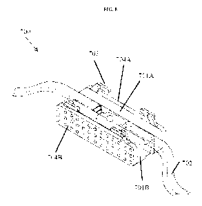
[0043] FIGS. 7-8 show exemplary schematic diagrams of a second tooth clamp
apparatus 700
herein. In some embodiments, the tooth clamp 700 includes one or more frames
704A 704B by
which it can be reversibly and fixedly coupled to the systems via one or more
coupling points
703. The coupling points can have different geometrical shapes. In some
embodiments, the
frames 704A 704B also provide a platform to retain one or more jaws 701A 701B,
e.g., patient
specific jaws, which act to envelop the tooth surfaces along a single axis,
e.g., along Y axis, from
two opposite directions, effectively clamping one or more teeth. In some
embodiments, the
patient specific jaws 701A 701B includes the first surface 701A 701B comprises
a shape adapted
to mate with the tooth surface of one or more teeth of the subject and a
second surface 701A
701B for attachment to the one or more frames 704A 704B. In some embodiments,
the first
surface 701A 701B envelopes a corresponding surface of the one or more teeth.
In some
embodiments, the shape of the first surface is selected from a collection of
pre-existing shapes. In
some embodiments, the first surface is three dimensional or two dimensional.
In some
embodiments, the second surface is three dimensional or two dimensional.
Existing suction tubes
702 can be leveraged with special interfacial pieces to allow compatibility
with engagement
orifices on the dental clamp 700.
[0044] In some embodiments, the patient-specific jaws 701A 701B and the first
surface 701A
701B are fabricated custom for each patient. In some embodiments, the first
surface 701A 701B
is generated at least partly based on three-dimensional surface data of one or
more teeth of the
subject. As a non-limiting example, teeth surface data is provided by a
surface scanning system
(such as but not limited to a Dentsply Sirona CEREC or Align Technologies
intraoral scanning
device). This teeth surface information can then be translated into a 3D model
of the teeth, with a
specific region picked for use based on the procedure (for one tooth or many
teeth). In some
embodiments, the 3D model of the teeth is then paired digitally with 3D models
of standard-sized
rigid material (e.g. plastic such as PEEK, Polycarbonate, Acrylic, etc.,
metal, polymer, etc)
(whether a single stock size or a range). The overlap of 3D tooth model and
standard-sized pieces
can then be locked at a pre-determined position, and a fabrication method can
be determined. In
some embodiments, the fabrication method includes one or more of: three-
dimensional printing,
CA 03099425 2020-11-04
WO 2019/215511 PCT/IB2019/000578
12
molding, casting, computer numerical control (CNC) machining, and/or machining
with a
toolpath Such method can be used to create cutaways in the standard sized
pieces, and then the
patient-specific jaws 701A 701B can be generated after removal of the
cutaways. In some
embodiment, fabrication of the jaws can be done either at the dental clinic
where the diagnostics
and treatment take place using in-house fabrication method (e.g., casting, CNC
machining, or 3D
printing), or alternatively at an external lab or centralized fabrication
facility.
[0045] In some embodiments, fixation points on the tooth clamp 700 acts to
secure a number of
suction ports 702. In some embodiments, the suction ports 702 are configured
for allowing
removal of debris and cooling/flushing water curing or after tooth cutting. In
some embodiments,
the suction ports functions together with equipment(s) including but not
limited to mechanisms to
provide negative pressure within. Additional accessories can be added to
equipment that provides
negative pressure in the dental office. In some embodiments, the accessories
include custom end
orifices to couple the suction ports 702 to portions of the tooth clamp 700,
along with necessary
branching mechanisms such that one suction device can be made into several
orifices to engage
with the tooth clamp. In some embodiments, the suction ports 702 are
configured to connect to
more than one orifice located at different portions of the clamp. The suction
ports can be attached
on the one or more frames, the one or more jaws, the one or more teeth of the
subject, or a
combination thereof In some embodiments, the suction ports include flexible
materials such as
plastic, polymer, rubber, silicone, or the like. In some embodiments, the
tooth clamp 700 includes
one or more irrigation orifices. Such irrigation orifices can be located at or
close to a distal end
(the end that is closer to the subject than a proximal end) of the system
configured for a dental
procedure. In some embodiments, the one or more irrigation orifices are
located to surround a
tooth cutting or tooth drilling burr of the system. In some embodiments, the
one or more
irrigation orifices are located to allow passage of a laser beam used for
tooth cutting or tooth
drilling. In some embodiments, lasers and water irrigation can be consolidated
in a coaxial
fashion, whether overlapping or annular in cross section.
[0046] In some embodiments, such suction ports are the same as existing dental
suction ports. In
some embodiments, the irrigation orifices include a cross-section that is
substantially circular. In
some embodiments, the irrigation orifices include a cross-section that is of
any arbitrary
geometrical shapes, non-limiting examples of such shapes include oval,
diamond, square, star,
etc. In some embodiments, such irrigation orifices are the same as existing
dental suction ports.
[0047] In some embodiments, the frames are of a single standard size or a
range of standard sizes
to allow for high volume fabrication prior to custom patient-specific jaw
fabrication.
CA 03099425 2020-11-04
WO 2019/215511 PCT/IB2019/000578
13
[0048] In some embodiments, the coupling points on the patient-specific jaws
provides fixation
of the tooth clamp to the system, e.g., ADD system, such that all degrees of
freedom are
substantially zero. In some embodiments, relative movement of the tooth clamp
to the system
during a dental procedure is within that of clinically acceptable thresholds.
In some
embodiments, the coupling points provides fixation such that the maximal
relative movement of
the tooth clamp with respect to the system is substantially zero. In some
embodiments, such
fixation can allow the system to enclose the tooth clamp and ensure that
debris is contained
within the tooth clamp. In some embodiments, such fixation advantageous allows
the suction port
702 to effectively and efficiently remove any rinsed material and excess
flushing water. In some
embodiments, the system performs a dental treatment or procedure with the
tooth clamp attached
thereon. For example, the dental drilling head within the ADD can execute a
cut to the desired
tooth. Once the operation is complete, the ADD can be removed from the tooth
clamp, and the
tooth clamp can then be removed from the teeth of the patient, allowing the
clinician to complete
their work on the target tooth/teeth.
[0049] In some embodiments, the tooth clamp can be installed onto the teeth
through clamping
force directed either through screw leverage, material elastic force
(analogous to traditional tooth
clamp), tensioned band force via screw leverage (see traditional dental band
clamp), or any other
applicable means to squeeze the two frame/patient-specific jaws in a parallel
and opposing
fashion, e.g., along the Y-axis, to clamp the exterior of the target region of
teeth.
[0050] In some embodiments, the tooth clamp is installed onto the teeth
through adhesive force
using an adhesive applied on the one or more jaws. In some embodiments, the
adhesive is at least
partly on the first surface. Such adhesive force can be activated by an
initial clamping force,
squeezing force or the like to allow sufficient contact of the adhesive with
the tooth surfaces. The
initial force can be removed after the adhesive force has taken place.
[0051] In some embodiments, the coupling points, the jaw(s), the frame(s), or
a combination
thereof includes rigid or semi-rigid material(s). In some embodiments, the
rigid material(s)
include one or more of: plastic, composite, metal, glass, porcelain, rubber,
and alloy. In some
embodiments, the rigid material(s) include one or more of: polyether ether
ketone (PEEK),
polycarbonate, and acrylic.
ADD Systems
[0052] In some embodiments, the tooth clamp disclosed herein that can be used
along with the
system for dental procedures allows for a datum to be set for machining. The
tooth clamp can act
to couple the ADD system's coordinates to that of the dental anatomy, thereby
allowing the ADD
CA 03099425 2020-11-04
WO 2019/215511 PCT/IB2019/000578
14
system to track where it is in reference to the teeth. Therefore, the tooth
clamp can allow a
common datum to be set between the two systems, a datum can be an origin by
which a common
(Cartesian, cylindrical, spherical, etc.) coordinate system is set.
[0053] In some embodiments, the datum is provided through coupling the system
to known
points on the frames and tracking known points through the tooth clamp to a
known position on a
given tooth, within an acceptable tolerance derived from the process of
creating the dental clamp.
Thus, the one or more jaws can provide positional reference during a dental
procedure. In some
embodiments, the one or more jaws provide an identical positional environment
of the one or
more teeth relative to the system at different time points. In some
embodiments, this
advantageously ensures that as between the time when teeth are scanned and the
operation takes
place, teeth can move, but the tooth clamp can reposition the teeth to their
previously scanned
position as the patient-specific jaws are fabricated to match the geometries
and positions of the
teeth when they are scanned.
[0054] As seen in FIGS. 9 and 10, in some embodiments, the ADD system 900
comprises a
clamp 700, a light guide 901 configured to transfer a laser from a laser
generator, a sensor 902,
and an irrigation nozzle 903. In some embodiments, the tooth clamp system 900
incorporates one
or more sensors 902 to measure the current dimensions of the tooth during the
process. In some
embodiments, the ADD system 900 can comprise two or more sensors 902 and two
or more
irrigation nozzles 903. As seen in FIG. 9, the sensors 902 and the irrigation
nozzles 903 can be
attached to the light guide 901. Alternatively, per FIG. 10, the irrigation
nozzles 903 can be
attached to the clamp 700. In some embodiments, at least one of the sensors
902 and the
irrigation nozzles 903 can be attached to the claim 700.
[0055] In some embodiments, the sensors 902 are optical. In some embodiments,
the sensors 902
determine the current dimensions of the tooth using machine-vision (image
analysis). In some
embodiments, the sensors 902 use optical-coherence tomography to determine the
current
dimensions of the tooth. In some embodiments, the sensors 902 use speckle
interferometry to
determine the current dimensions of the tooth. In some embodiments, the
sensors 902 use
ultrasound to determine the current dimensions of the tooth. In some
embodiments, the current
dimensions of the tooth as determined by the sensors 902 are compared to the
surgical plan to
determine the progress of the dental procedure.
[0056] In some embodiments, the current dimensions of the tooth as determined
by the sensors
902 are compared to prior dimensions of the tooth to determine the rate of
tissue removal. In
some embodiments, the prior dimensions of the tooth are determined using
previous
measurements by the sensors 902 during the same procedure. In some
embodiments, the prior
CA 03099425 2020-11-04
WO 2019/215511 PCT/IB2019/000578
dimensions of the tooth are determined using prior measurements of the tooth
performed using
other means which will be apparent to those knowledgeable in the art. As a non-
limiting
example, teeth surface data is provided by a surface scanning system (such as
but not limited to a
Dentsply Sirona CEREC or Align Technologies intraoral scanning device).
[0057] In some embodiments, the current and past dimensions of the tooth are
used to control the
cutting speed of the automated dental drill (ADD) for optimal tissue removal.
In some
embodiments, the rate of tissue removal (as determined by current and past
dimensions of the
tooth) is used to distinguish healthy tissue from unhealthy tissue. As a non-
limiting example,
dense tooth material will cut or ablate at a lower rate than caries. In some
embodiments, the rate
of tissue removal (as determined by current and past dimensions of the tooth)
is used to
distinguish gingiva from tooth. In some embodiments, the spatial distribution
of tissue-removal
rate is used to determine the extent of tissue to be removed, and determine
the progress and
completion of the procedure.
[0058] In some embodiments, the determination of procedural progress or
completion, as
determined using the tissue-removal rate, is performed using an automated
control system. As a
non-limiting example, the automated control system can be implemented using a
computer. As
another non-limiting example, the automated control system can be implemented
using a
microcontroller. As a third non-limiting example, the automated control system
can be
implemented using a Field-Programmable Gate Array (FPGA).
[0059] Per FIG. 11, the ADD system 100 can comprise a translational drive
assembly 1101 and
a laser generating source 1102 that generates a laser beam for cutting or
drilling of the teeth. In
some embodiments, the laser generating source 1102 generates a concentrated
beam within a
specific treatment volume 1103, which may or may not be coincident with the
surface of a tooth.
The focused laser in the treatment volume 1103 can enable phase change (e.g.
water
microbubbles), chemical change (e.g. pIRL), multi-photon ionization, or any
combination thereof
within the tooth. In some embodiments, the laser is generated at the distal
end of the system, e.g.,
by incorporating a laser generating source in an ADD system. In some
embodiments, the laser is
generated at a proximal end of the system and is transmitted to the distal end
of the system. In
some embodiments, the clamp can be sized (e.g., recessed along z direction) so
that it allows
laser access to the teeth of the subject.
[0060] In some embodiments, the laser beam has a wavelength of about 0.1 um to
about 50 um.
In some embodiments, the laser beam has a wavelength of about 0.1 IA um to
about 0.5 um, about
0.1 um to about 1 um, about 0.1 um to about 5 um, about 0.1 um to about 10 um,
about 0.1 um to
about 15 um, about 0.1 um to about 20 um, about 0.1 um to about 25 um, about
0.1 um to about
CA 03099425 2020-11-04
WO 2019/215511 PCT/IB2019/000578
16
30 um, about 0.1 um to about 35 um, about 0.1 um to about 40 um, about 0.1 um
to about 50 um,
about 0.5 um to about 1 um, about 0.5 um to about 5 um, about 0.5 um to about
10 um, about 0.5
um to about 15 um, about 0.5 um to about 20 um, about 0.5 um to about 25 um,
about 0.5 um to
about 30 um, about 0.5 um to about 35 um, about 0.5 um to about 40 um, about
0.5 um to about
50 um, about 1 um to about 5 um, about 1 um to about 10 um, about 1 um to
about 15 um, about
1 um to about 20 um, about 1 um to about 25 um, about 1 um to about 30 um,
about 1 um to
about 35 um, about 1 um to about 40 um, about 1 um to about 50 um, about 5 um
to about 10 um,
about 5 um to about 15 um, about 5 um to about 20 um, about 5 um to about 25
um, about 5 um
to about 30 um, about 5 um to about 35 um, about 5 um to about 40 um, about 5
um to about 50
um, about 10 um to about 15 um, about 10 um to about 20 um, about 10 um to
about 25 um,
about 10 um to about 30 um, about 10 um to about 35 um, about 10 um to about
40 um, about 10
um to about 50 um, about 15 um to about 20 um, about 15 um to about 25 um,
about 15 um to
about 30 um, about 15 um to about 35 um, about 15 um to about 40 um, about 15
um to about 50
um, about 20 um to about 25 um, about 20 um to about 30 um, about 20 um to
about 35 um,
about 20 um to about 40 um, about 20 um to about 50 um, about 25 um to about
30 um, about 25
um to about 35 um, about 25 um to about 40 um, about 25 um to about 50 um,
about 30 um to
about 35 um, about 30 um to about 40 um, about 30 um to about 50 um, about 35
um to about 40
um, about 35 um to about 50 um, or about 40 um to about 50 um. In some
embodiments, the laser
beam has a wavelength of about 0.1 um, about 0.5 um, about 1 um, about 5 um,
about 10 um,
about 15 um, about 20 um, about 25 um, about 30 um, about 35 um, about 40 um,
or about 50
um. In some embodiments, the laser beam has a wavelength of at least about 0.1
um, about 0.5
um, about 1 um, about 5 um, about 10 um, about 15 um, about 20 um, about 25
um, about 30 um,
about 35 um, or about 40 um. In some embodiments, the laser beam has a
wavelength of at most
about 0.5 um, about 1 um, about 5 um, about 10 um, about 15 um, about 20 um,
about 25 um,
about 30 um, about 35 um, about 40 um, or about 50 um.
[0061] In some embodiments, the laser beam generated herein by the system is
configured to
provide different spot sizes suitable for different cutting or drilling
applications. In some
embodiments, the laser beam generated herein is switched on and off in a
pulsed, periodic
manner during cutting. In some embodiments, the duration and time between "on"
pulses can be
controlled to optimize the cutting or drilling process. In some embodiments,
the optical power of
the laser beam generated herein can be controlled to optimize the cutting or
drilling process. In
some embodiments, the optical power of the laser beam generated herein can be
varied from
pulse to pulse in order to optimize the cutting or drilling process. In some
embodiments, the
optical power of the laser beam generated herein can be varied within a pulse
in order to optimize
CA 03099425 2020-11-04
WO 2019/215511 PCT/IB2019/000578
17
the cutting or drilling process. In some embodiments, the laser-beam spot can
be scanned within
a localized region of the tooth, to optimize removal of tooth material at that
region. In some
embodiments, the laser-beam spot can be scanned within a localized region of
the tooth, to
optimize removal of gingiva at that region. In some embodiments, several or
all of the spot size,
spot scanning pattern, pulse repletion rate, pulse duration, pulse duty cycle,
pulse pattern, and
laser optical power can be controlled in concert to optimize the removal of
tooth material. In
some embodiments, several or all of the spot size, spot scanning pattern,
pulse repletion rate,
pulse duration, pulse duty cycle, pulse pattern, and laser optical power can
be controlled in
concert to optimize the removal of gingiva.
[0062] In some embodiments, the laser generating source is titanium-sapphire
(Ti:Sapph) laser.
In some embodiments, the laser generating source emits light of wavelength
between 0.65 p.m
and 1.10 p.m. In some embodiments, the laser generating source emits light of
center wavelength
0.78 p.m. In some embodiments, the laser generating source emits light of
center wavelength 0.80
[0063] In some embodiments, the laser generating source is a fiber laser,
consisting of
Ytterbium-doped silica fiber. In some embodiments, the laser generating source
emits a range of
wavelengths between about 1.00 p.m and about 1.20 p.m. In some embodiments,
the laser
generating source emits light of center wavelength of about 1.03 p.m. In some
embodiments, the
laser generating source emits light of center wavelength of about 1.04 p.m.
[0064] In some embodiments, the laser generating source is a fiber laser,
consisting of
Ytterbium-doped silica fiber. In some embodiments, the laser generating source
emits a range of
wavelengths between about 1.45 p.m and about 1.65 p.m. In some embodiments,
the laser
generating source emits light of center wavelength of avbout 1.55 p.m.
[0065] In some embodiments, the laser generating source is an neodymium-doped
yttrium
aluminum garnet laser (neodymium YAG, Nd:YAG). In some embodiments, the laser
generating
source emits light having a wavelength of about 0.946 p.m. In some
embodiments, the laser
generating source emits light having a wavelength of about 1.12 p.m. In some
embodiments, the
laser generating source emits light having a wavelength of about 1.32 p.m. In
some embodiments,
the laser generating source emits light having a wavelength of about 1.44 p.m.
In some
embodiments, the laser generating source is an erbium-doped yttrium aluminum
garnet laser
(erbium YAG, Er:YAG). In some embodiments, the laser generating source emits
light having a
wavelength of about 2.94 [tm.
[0066] In some embodiments, the laser generating source is a carbon-dioxide
laser. In some
embodiments, the laser generating source emits light having a wavelength of
about 10 p.m. In
CA 03099425 2020-11-04
WO 2019/215511 PCT/IB2019/000578
18
some embodiments, the laser generating source emits light having a wavelength
of about 10.6
p.m. In some embodiments, the laser generating source emits light having a
wavelength of about
10.3 p.m. In some embodiments, the laser generating source emits light having
a wavelength of
about 9.6 p.m. In some embodiments, the laser generating source is a
picosecond high-powered
laser having a wavelength of about 3 m.
[0067] In some embodiments, the laser generating source is a fiber laser,
consisting of Erbium-
doped fluoride glass fiber. In some embodiments, the laser generating source
emits a range of
wavelengths between about 2.0 p.m and about 4.0 p.m. In some embodiments, the
laser generating
source emits light of center wavelength 2.80 p.m. Er3+Er3+-doped fluoride
glass
[0068] In some embodiments, the laser generating source emits light of
approximate wavelength
9.3 p.m, nearing the peak absorption of hydroxyapatite. In some embodiments,
the gain medium
of the laser generating source is a carbon-dioxide gas that includes an oxygen-
18 isotope. In
some embodiments, the laser herein includes an isotopic CO2 laser that
vaporizes enamel and
gingiva. In some embodiments, the laser is configured to allow fast and
efficient cutting at any
angle, with more speed, precision and less bleeding than traditional cutting
or drilling methods.
In some embodiments, the system comprising a laser beam for tooth or gingiva
cutting or drilling
does not require anesthesia of the subject.
[0069] In some embodiments, automation, e.g., through optical tracking
methods, can required to
judge how much material has been removed using the laser cutting methods and
the laser
generating system herein.
Control Systems
[0070] Referring to FIG. 12, the operation of dental treatment system 60 is
described as follows.
The central processing unit 62 can control the automated dental drill 10 to
remove a region of the
target tooth. The dental treatment system 60 can include input devices 120,
122 which can, for
example, be a keyboard and mouse that receive surgical instructions from a
user (i.e., dentist) for
providing the surgical intervention. The instructions can be received by the
central processing
unit 62. Characteristically, the surgical instructions including visual
indications 124 on the image
of a target tooth are indications of the treatment. A control program 70 can
guide the user through
the dental protocols via a series of onscreen prompts (i.e., the user
interface). In this context,
actions attributable to control program 70 are understood to mean the
execution of the relevant
steps by central processing unit 62. In a variation, the dental treatment
system 60 can include
static memory 130 for storing patient profiles and records, which can be
accessed by the user. In
some embodiments, the central processing unit 62 can also display a load
screen that shows a
CA 03099425 2020-11-04
WO 2019/215511 PCT/IB2019/000578
19
series of patient records and gives the option to load an existing patient, or
create a new patient
record.
[0071] Additional aspects and advantages of the present disclosure will become
readily apparent
to those skilled in this art from the following detailed description, wherein
only illustrative
embodiments of the present disclosure are shown and described. As will be
realized, the present
disclosure is capable of other and different embodiments, and its several
details are capable of
modifications in various obvious respects, all without departing from the
disclosure.
Accordingly, the drawings and description are to be regarded as illustrative
in nature, and not as
restrictive.
[0072] While various embodiments of the invention have been shown and
described herein, it
will be obvious to those skilled in the art that such embodiments are provided
by way of example
only. Numerous variations, changes, and substitutions can occur to those
skilled in the art
without departing from the invention. It should be understood that various
alternatives to the
embodiments of the invention described herein can be employed.
Computing Systems
[0073] Referring to FIG. 13, a block diagram is shown depicting an exemplary
machine that
includes a computer system 1300 (e.g., a processing or computing system)
within which a set of
instructions can execute for causing a device to perform or execute any one or
more of the
aspects and/or methodologies for static code scheduling of the present
disclosure. The
components in FIG. 13 are examples only and do not limit the scope of use or
functionality of
any hardware, software, embedded logic component, or a combination of two or
more such
components implementing particular embodiments.
[0074] Computer system 1300 may include one or more processors 1301, a memory
1303, and a
storage 1308 that communicate with each other, and with other components, via
a bus 1340. The
bus 1340 may also link a display 1332, one or more input devices 1333 (which
may, for example,
include a keypad, a keyboard, a mouse, a stylus, etc.), one or more output
devices 1334, one or
more storage devices 1335, and various tangible storage media 1336. All of
these elements may
interface directly or via one or more interfaces or adaptors to the bus 1340.
For instance, the
various tangible storage media 1336 can interface with the bus 1340 via
storage medium
interface 1326. Computer system 1300 may have any suitable physical form,
including but not
limited to one or more integrated circuits (ICs), printed circuit boards
(PCBs), mobile handheld
devices (such as mobile telephones or PDAs), laptop or notebook computers,
distributed
computer systems, computing grids, or servers.
CA 03099425 2020-11-04
WO 2019/215511 PCT/IB2019/000578
[0075] Computer system 1300 includes one or more processor(s) 1301 (e.g.,
central processing
units (CPUs) or general purpose graphics processing units (GPGPUs)) that carry
out functions.
Processor(s) 1301 optionally contains a cache memory unit 1302 for temporary
local storage of
instructions, data, or computer addresses. Processor(s) 1301 are configured to
assist in execution
of computer readable instructions. Computer system 1300 may provide
functionality for the
components depicted in FIG. 13 as a result of the processor(s) 1301 executing
non-transitory,
processor-executable instructions embodied in one or more tangible computer-
readable storage
media, such as memory 1303, storage 1308, storage devices 1335, and/or storage
medium 1336.
The computer-readable media may store software that implements particular
embodiments, and
processor(s) 1301 may execute the software. Memory 1303 may read the software
from one or
more other computer-readable media (such as mass storage device(s) 1335, 1336)
or from one or
more other sources through a suitable interface, such as network interface
1320. The software
may cause processor(s) 1301 to carry out one or more processes or one or more
steps of one or
more processes described or illustrated herein. Carrying out such processes or
steps may include
defining data structures stored in memory 1303 and modifying the data
structures as directed by
the software.
[0076] The memory 1303 may include various components (e.g., machine readable
media)
including, but not limited to, a random access memory component (e.g., RAM
1304) (e.g., static
RAM (SRAM), dynamic RAM (DRAM), ferroelectric random access memory (FRAM),
phase-
change random access memory (PRAM), etc.), a read-only memory component (e.g.,
ROM
1305), and any combinations thereof. ROM 1305 may act to communicate data and
instructions
unidirectionally to processor(s) 1301, and RAM 1304 may act to communicate
data and
instructions bidirectionally with processor(s) 1301. ROM 1305 and RAM 1304 may
include any
suitable tangible computer-readable media described below. In one example, a
basic input/output
system 1306 (BIOS), including basic routines that help to transfer information
between elements
within computer system 1300, such as during start-up, may be stored in the
memory 1303.
[0077] Fixed storage 1308 is connected bidirectionally to processor(s) 1301,
optionally through
storage control unit 1307. Fixed storage 1308 provides additional data storage
capacity and may
also include any suitable tangible computer-readable media described herein.
Storage 1308 may
be used to store operating system 1309, executable(s) 1310, data 1311,
applications 1312
(application programs), and the like. Storage 1308 can also include an optical
disk drive, a solid-
state memory device (e.g., flash-based systems), or a combination of any of
the above.
Information in storage 1308 may, in appropriate cases, be incorporated as
virtual memory in
memory 1303.
CA 03099425 2020-11-04
WO 2019/215511 PCT/IB2019/000578
21
[0078] In one example, storage device(s) 1335 may be removably interfaced with
computer
system 1300 (e.g., via an external port connector (not shown)) via a storage
device interface
1325. Particularly, storage device(s) 1335 and an associated machine-readable
medium may
provide non-volatile and/or volatile storage of machine-readable instructions,
data structures,
program modules, and/or other data for the computer system 1300. In one
example, software may
reside, completely or partially, within a machine-readable medium on storage
device(s) 1335. In
another example, software may reside, completely or partially, within
processor(s) 1301.
[0079] Bus 1340 connects a wide variety of subsystems. Herein, reference to a
bus may
encompass one or more digital signal lines serving a common function, where
appropriate. Bus
1340 may be any of several types of bus structures including, but not limited
to, a memory bus, a
memory controller, a peripheral bus, a local bus, and any combinations
thereof, using any of a
variety of bus architectures. As an example and not by way of limitation, such
architectures
include an Industry Standard Architecture (ISA) bus, an Enhanced ISA (EISA)
bus, a Micro
Channel Architecture (MCA) bus, a Video Electronics Standards Association
local bus (VLB), a
Peripheral Component Interconnect (PCI) bus, a PCI-Express (PCI-X) bus, an
Accelerated
Graphics Port (AGP) bus, HyperTransport (HTX) bus, serial advanced technology
attachment
(SATA) bus, and any combinations thereof
[0080] Computer system 1300 may also include an input device 1333. In one
example, a user of
computer system 1300 may enter commands and/or other information into computer
system 1300
via input device(s) 1333. Examples of an input device(s) 1333 include, but are
not limited to, an
alpha-numeric input device (e.g., a keyboard), a pointing device (e.g., a
mouse or touchpad), a
touchpad, a touch screen, a multi-touch screen, a joystick, a stylus, a
gamepad, an audio input
device (e.g., a microphone, a voice response system, etc.), an optical
scanner, a video or still
image capture device (e.g., a camera), and any combinations thereof. In some
embodiments, the
input device is a Kinect, Leap Motion, or the like. Input device(s) 1333 may
be interfaced to bus
1340 via any of a variety of input interfaces 1323 (e.g., input interface
1323) including, but not
limited to, serial, parallel, game port, USB, FIREWIRE, THUNDERBOLT, or any
combination
of the above.
[0081] In particular embodiments, when computer system 1300 is connected to
network 1330,
computer system 1300 may communicate with other devices, specifically mobile
devices and
enterprise systems, distributed computing systems, cloud storage systems,
cloud computing
systems, and the like, connected to network 1330. Communications to and from
computer system
1300 may be sent through network interface 1320. For example, network
interface 1320 may
receive incoming communications (such as requests or responses from other
devices) in the form
CA 03099425 2020-11-04
WO 2019/215511 PCT/IB2019/000578
22
of one or more packets (such as Internet Protocol (IP) packets) from network
1330, and computer
system 1300 may store the incoming communications in memory 1303 for
processing. Computer
system 1300 may similarly store outgoing communications (such as requests or
responses to
other devices) in the form of one or more packets in memory 1303 and
communicated to network
1330 from network interface 1320. Processor(s) 1301 may access these
communication packets
stored in memory 1303 for processing.
[0082] Examples of the network interface 1320 include, but are not limited to,
a network
interface card, a modem, and any combination thereof. Examples of a network
1330 or network
segment 1330 include, but are not limited to, a distributed computing system,
a cloud computing
system, a wide area network (WAN) (e.g., the Internet, an enterprise network),
a local area
network (LAN) (e.g., a network associated with an office, a building, a campus
or other relatively
small geographic space), a telephone network, a direct connection between two
computing
devices, a peer-to-peer network, and any combinations thereof. A network, such
as network
1330, may employ a wired and/or a wireless mode of communication. In general,
any network
topology may be used.
[0083] Information and data can be displayed through a display 1332. Examples
of a display
1332 include, but are not limited to, a cathode ray tube (CRT), a liquid
crystal display (LCD), a
thin film transistor liquid crystal display (TFT-LCD), an organic liquid
crystal display (OLED)
such as a passive-matrix OLED (PMOLED) or active-matrix OLED (AMOLED) display,
a
plasma display, and any combinations thereof. The display 1332 can interface
to the processor(s)
1301, memory 1303, and fixed storage 1308, as well as other devices, such as
input device(s)
1333, via the bus 1340. The display 1332 is linked to the bus 1340 via a video
interface 1322,
and transport of data between the display 1332 and the bus 1340 can be
controlled via the
graphics control 1321. In some embodiments, the display is a video projector.
In some
embodiments, the display is a head-mounted display (HMD) such as a VR headset.
In further
embodiments, suitable VR headsets include, by way of non-limiting examples,
HTC Vive,
Oculus Rift, Samsung Gear VR, Microsoft HoloLens, Razer OSVR, FOVE VR, Zeiss
VR One,
Avegant Glyph, Freefly VR headset, and the like. In still further embodiments,
the display is a
combination of devices such as those disclosed herein.
[0084] In addition to a display 1332, computer system 1300 may include one or
more other
peripheral output devices 1334 including, but not limited to, an audio
speaker, a printer, a storage
device, and any combinations thereof. Such peripheral output devices may be
connected to the
bus 1340 via an output interface 1324. Examples of an output interface 1324
include, but are not
CA 03099425 2020-11-04
WO 2019/215511 PCT/IB2019/000578
23
limited to, a serial port, a parallel connection, a USB port, a FIREWIRE port,
a
THUNDERBOLT port, and any combinations thereof.
[0085] In addition or as an alternative, computer system 1300 may provide
functionality as a
result of logic hardwired or otherwise embodied in a circuit, which may
operate in place of or
together with software to execute one or more processes or one or more steps
of one or more
processes described or illustrated herein. Reference to software in this
disclosure may encompass
logic, and reference to logic may encompass software. Moreover, reference to a
computer-
readable medium may encompass a circuit (such as an IC) storing software for
execution, a
circuit embodying logic for execution, or both, where appropriate. The present
disclosure
encompasses any suitable combination of hardware, software, or both.
[0086] Those of skill in the art will appreciate that the various illustrative
logical blocks,
modules, circuits, and algorithm steps described in connection with the
embodiments disclosed
herein may be implemented as electronic hardware, computer software, or
combinations of both.
To clearly illustrate this interchangeability of hardware and software,
various illustrative
components, blocks, modules, circuits, and steps have been described above
generally in terms of
their functionality.
[0087] The various illustrative logical blocks, modules, and circuits
described in connection with
the embodiments disclosed herein may be implemented or performed with a
general purpose
processor, a digital signal processor (DSP), an application specific
integrated circuit (ASIC), a
field programmable gate array (FPGA) or other programmable logic device,
discrete gate or
transistor logic, discrete hardware components, or any combination thereof
designed to perform
the functions described herein. A general purpose processor may be a
microprocessor, but in the
alternative, the processor may be any conventional processor, controller,
microcontroller, or state
machine. A processor may also be implemented as a combination of computing
devices, e.g., a
combination of a DSP and a microprocessor, a plurality of microprocessors, one
or more
microprocessors in conjunction with a DSP core, or any other such
configuration.
[0088] The steps of a method or algorithm described in connection with the
embodiments
disclosed herein may be embodied directly in hardware, in a software module
executed by one or
more processor(s), or in a combination of the two. A software module may
reside in RAM
memory, flash memory, ROM memory, EPROM memory, EEPROM memory, registers, hard
disk, a removable disk, a CD-ROM, or any other form of storage medium known in
the art. An
exemplary storage medium is coupled to the processor such the processor can
read information
from, and write information to, the storage medium. In the alternative, the
storage medium may
be integral to the processor. The processor and the storage medium may reside
in an ASIC. The
CA 03099425 2020-11-04
WO 2019/215511 PCT/IB2019/000578
24
ASIC may reside in a user terminal. In the alternative, the processor and the
storage medium may
reside as discrete components in a user terminal.
[0089] In accordance with the description herein, suitable computing devices
include, by way of
non-limiting examples, server computers, desktop computers, laptop computers,
notebook
computers, sub-notebook computers, netbook computers, netpad computers, set-
top computers,
media streaming devices, handheld computers, Internet appliances, mobile
smartphones, tablet
computers, personal digital assistants, video game consoles, and vehicles.
Those of skill in the art
will also recognize that select televisions, video players, and digital music
players with optional
computer network connectivity are suitable for use in the system described
herein. Suitable tablet
computers, in various embodiments, include those with booklet, slate, and
convertible
configurations, known to those of skill in the art.
[0090] In some embodiments, the computing device includes an operating system
configured to
perform executable instructions. The operating system is, for example,
software, including
programs and data, which manages the device's hardware and provides services
for execution of
applications. Those of skill in the art will recognize that suitable server
operating systems
include, by way of non-limiting examples, FreeBSD, OpenBSD, NetBSD , Linux,
Apple Mac
OS X Server , Oracle Solaris , Windows Server , and Novell NetWare . Those
of skill in
the art will recognize that suitable personal computer operating systems
include, by way of non-
limiting examples, Microsoft Windows , Apple Mac OS X , UNIX , and UNIX-like
operating systems such as GNU/Linux . In some embodiments, the operating
system is provided
by cloud computing. Those of skill in the art will also recognize that
suitable mobile smartphone
operating systems include, by way of non-limiting examples, Nokia Symbian
OS, Apple
i0S , Research In Motion BlackBerry OS , Google Android , Microsoft Windows
Phone OS, Microsoft Windows Mobile OS, Linux , and Palm Web0S . Those of
skill
in the art will also recognize that suitable media streaming device operating
systems include, by
way of non-limiting examples, Apple TV , Roku , Boxee , Google TV , Google
Chromecast , Amazon Fire , and Samsung HomeSync . Those of skill in the art
will also
recognize that suitable video game console operating systems include, by way
of non-limiting
examples, Sony P53 , Sony 1354 , Microsoft Xbox 360 , Microsoft Xbox One,
Nintendo Wii , Nintendo Wii U , and Ouya .
[0091] While preferred embodiments of the present invention have been shown
and described
herein, it will be obvious to those skilled in the art that such embodiments
are provided by way of
example only. It is not intended that the invention be limited by the specific
examples provided
within the specification. While the invention has been described with
reference to the
CA 03099425 2020-11-04
WO 2019/215511 PCT/IB2019/000578
aforementioned specification, the descriptions and illustrations of the
embodiments herein are not
meant to be construed in a limiting sense. Numerous variations, changes, and
substitutions will
now occur to those skilled in the art without departing from the invention.
Furthermore, it shall
be understood that all aspects of the invention are not limited to the
specific depictions,
configurations or relative proportions set forth herein which depend upon a
variety of conditions
and variables. It should be understood that various alternatives to the
embodiments of the
invention described herein can be employed in practicing the invention. It is
therefore
contemplated that the invention shall also cover any such alternatives,
modifications, variations
or equivalents. It is intended that the following claims define the scope of
the invention and that
methods and structures within the scope of these claims and their equivalents
be covered thereby.