Note: Descriptions are shown in the official language in which they were submitted.
CA 03100093 2020-11-12
1
Dispensing Head And Dispensing Device For The Metered Dispensing Of Liquid
Preparations, And Possible Uses
The present invention relates to a dispensing head for a dispensing device and
to a dispensing device provided with the dispensing head for the metered
dispensing of liquid preparations. The dispensing head here comprises a
special valve that comprises at least one sealing lip by which a passage
channel introduced in the dispensing head to dispense the liquid preparation
can be closed. The present invention is characterized here by the simplicity
of
the dispensing head and by the economic advantages in the manufacture
associated therewith.
WO 2018/010889 relates to a pump head that enables a metered dispensing
of fluids and a metering device that can, for example, be configured as a
squeeze bottle, with the metering device comprising a correspondingly
configured pump head. The pump head described there is, however, not
sufficiently pressure sensitive so that the targeted metered dispensing of a
specific volume of a fluid to be metered is made more difficult.
It is the object of the present invention to provide a dispensing head for a
dispensing device for the metered dispensing of liquid preparations or to
provide a corresponding dispensing device that is as pressure sensitive as
possible and thus facilitates the dispensing of an exactly metered quantity of
a
fluid to be dispensed - in particular liquids having low surface tension such
as
aqueous solutions. The dispensing head should additionally have a valve that
has a design that is as simple as possible. This object is achieved by the
features of claim 1 with respect to a dispensing head and by the features of
claim 16 with respect to a dispensing device. Possibilities of use of the
dispensing device are set forth in claim 19.
The present invention thus relates to a dispensing head for a dispensing
device for the metered dispensing of liquid preparations comprising a passage
channel that has an inlet opening arranged at the inner side and an outer
LEGAL 35036019.1 1012855-277931 KB/sz
Date Recue/Date Received 2020-11-12
CA 03100093 2020-11-12
2
dispensing opening for liquid preparations, wherein the inlet opening
connects an inner space to an outer environment via the passage channel and
a valve comprising a valve body that is arranged on the side of the inner
space
above the inlet opening and the inlet opening is designed as reversibly
sealingly closable with respect to an inner space for the liquid preparation,
wherein the valve body has at least one sealing lip that is formed on a side
of
the valve body facing the inlet opening and seals the inner space with respect
to the inlet opening when the valve body closes the inlet opening.
The dispensing head thus has a passage channel by which liquid preparation
to be dispenses can be dispensed from an inner side (on which the valve is
arranged) to the outer side. The dispensing head for this purpose comprises a
passage channel that has an inlet opening arranged on the inner side and an
outer dispensing opening. The valve is configured here such that it can
independently close the inlet opening of the passage channel (and thus the
complete passage channel) in some operating states of the dispensing head.
In accordance with the invention, the valve body has at least one sealing lip
by
which it is made possible to effectively close the inlet opening of the
passage
channel. The valve body itself is here formed as movable with respect to the
inlet opening so that it is possible in an open state of the valve that liquid
preparation to be metered can be dispensed into the inlet opening and thus
into the passage channel and to the outside via the dispensing opening.
The valve in accordance with the invention thus makes it possible that the
fluid to be dispensed can pass between the dispensing head and the at least
one sealing lip or the plurality of sealing lips in the event that the valve
body is
not pressed at all or is pressed with a sufficiently small pressing force by
the
fluid to be dispensed to the inlet opening of the passage channel. For the
case
that the pressure on the valve body is increased (for example via the fluid to
be dispensed) or for the exemplary case that a pressure increase occurs, the
valve body having the at least one sealing lip arranged thereon is pressed
sufficiently forcefully onto the dispensing head and thus reliably closes the
inlet opening of the passage channel. The passage channel is closed by the
valve in this operating state.
LEGAL 35036019.1 1012855-277931 KB/sz
Date Recue/Date Received 2020-11-12
CA 03100093 2020-11-12
3
The valve is thus open when no pressure is applied to the squeeze bottle;
there is then a narrow gap between the at least one sealing lip of the valve
body and the wall of the dispensing head. The gap here, however, has such
small dimensions that no fluid can exit, even if the metering device having
the
dispensing head in accordance with the invention is positioned with the outlet
opening facing downward (e.g. during transport or storage of the metering
device in a corresponding position such as in a handbag or in a trouser
pocket). This is due to the surface tension of the fluid and to the small
distance between the valve and the wall of the dispensing head. The
dispensing of the fluid to be metered takes place by exerting a pressure on
the fluid present in the interior of the metering device, for example in that
pressure is exerted on a squeeze bottle. The dispensing of the fluid takes
place here in a metered manner until a closure of the valve takes place. The
valve is closed by pressure on the squeeze bottle and after dispensing the
defined metered volume in that a fluidic closure of the outlet passage takes
place even if the pressure continues.
When the metering device is stored facing downward (i.e. when the valve is
arranged above the passage channel), the fluid to be metered can flow into
the passage channel due to the fact that the valve is open. On an actuation of
the metering device (i.e. for the case that pressure is exerted on the stored
fluid in that e.g. a squeeze bottle is pressed), a metered dispensing of the
fluid
then takes place through the valve until the closure of the passage channel.
The metered quantity is thus defined by a metering stroke of the valve.
If there is air between the valve and the liquid, that is e.g. when storing
the
metering device facing upward (i.e. when the valve is arranged below the
passage channel), only air is present in the passage channel since the liquid
flows back into the storage container due to gravity. Only a stroke quantity
of
air thus exits on an exertion of pressure.
The present invention is in particular characterized by the simplicity of the
valve that can, for example, be formed in one piece and that can be placed
into the dispensing head. In this respect, no further fastening means for the
valve are required; both the dispensing head and the valve can equally be
LEGAL 35036019.1 1012855-277931 KB/sz
Date Recue/Date Received 2020-11-12
CA 03100093 2020-11-12
4
produced from a single material so that foreign materials such as metals or
complex mechanical constructions become superfluous.
In accordance with a preferred embodiment, the valve body comprises at
least two sealing lips, an inner sealing lip, and an outer sealing lip.
It is further preferred that the at least one sealing lip, in particular the
inner
sealing lip and the outer sealing lip, is/are arranged concentrically at the
valve
body. Due to the concentric design, the inlet opening, that can equally be
formed as circular in cross-section, for the passage channel (optionally
likewise equally circular), can, for example, be reliably surrounded and thus
sealed with respect to the inner space.
It is in particular advantageous for the manufacture of the valve if the valve
body and the at least one sealing lip are formed in one piece.
It is further preferred if the at least one sealing lip has a height in the
direction
of the inlet opening of 0.05 to 1 mm, preferably 0.1 to 0.5 mm.
The at least one sealing lip (7a, 7b) can, for example, have a width of 0.05
to
1 mm, preferably 0.1 to 0.4 mm.
It is further preferred if the at least one sealing lip is formed from a
thermoplastic or elastomeric plastic, in particular from a polyolefin such as
polyethylene, polypropylene, polystyrene, or a polyamide such as PA6, PA66,
PA12.
It is equally possible that the valve comprises a frame that has at least one
fastening element to which the valve body is fixed, with the frame being
fastened to the dispensing head.
It is in particular of advantage here if the valve body, the frame, and the at
least one fastening element are formed in one piece.
LEGAL 35036019.1 1012855-
277931 KB/sz
Date Recue/Date Received 2020-11-12
CA 03100093 2020-11-12
It is further preferred in the previously named embodiment if the dispensing
head has a cutout into which the frame with the valve body is fitted in a
force
transmitting or shape matched manner.
5 A further preferred embodiment provides that the valve is loosely
received in
a cutout of the dispensing head and is formed as vertically movable in the
cutout.
It is in particular of advantage in the previously named embodiment if the
valve body is dimensioned such that the liquid preparation can flow between
the valve body and a wall bounding the cutout.
It is in particular preferred for the case that the valve body is loosely
placed
into the cutout to secure the valve or the valve body. Provision is made in
accordance with this preferred embodiment that the cutout has a boundary
that prevents a complete vertical leading of the valve out of the cutout.
It is further preferred that the valve body has a guide prolongation that
engages into the passage channel and that has a smaller cross-section than
the passage channel.
It can in particular be of advantage here if the guide prolongation and the
valve body are formed in one piece.
The present invention additionally relates to a dispensing device for the
metered dispensing of liquid preparations comprising a dispensing head in
accordance with one of the preceding claims and a flexible storage container,
with the dispensing head being installed on the storage container in a
fluidically sealed manner.
The storage container is here in particular formed as a squeeze bottle that
can
be actuated by pressure.
The storage container can here be selected from a material selected from the
group comprising thermoplastics and elastomeric plastics, in particular from a
LEGAL 35036019.1 1012855-
277931 KB/sz
Date Recue/Date Received 2020-11-12
CA 03100093 2020-11-12
6
polyolefin such as polyethylene, polypropylene, polystyrene, or a polyamide
such as PA6, PA66, PA12.
The invention further relates to the use of a previously named dispensing
device in accordance with the invention. The use possibilities are here, in
accordance with the invention, the storage and/or metered dispensing of
ophthalmic products, in particular eye drops; rhinological products, in
particular nose drops; fluids, gels, creams, pastes, foods, and food
supplements.
The present invention was illustrated in more detail with reference to the
following Figures and examples without restricting the invention to the shown
specific circumstances.
There are shown:
Figure 1: a first embodiment in accordance with the invention of a
dispensing head and of a dispensing device in an opened state;
Figure 2a: the dispensing device in accordance with the first embodiment
- after the completed dispensing of the metered volume and
thus the closure of the valve;
Figure 2b: the dispensing device in accordance with the first
embodiment
in the equalized pressure state, i.e. on the equalization of the
suction power in the squeeze bottle by air inflow;
Figure 3: a second embodiment in accordance with the invention of a
dispensing device in an opened state;
Figure 4a: the dispensing device in accordance with the second
embodiment after the completed dispensing of the metered
volume and thus the closure of the valve;
and
LEGAL 35036019.1 1012855-277931 KB/sz
Date Recue/Date Received 2020-11-12
CA 03100093 2020-11-12
7
Figure 4b: the dispensing device in accordance with the second
embodiment in the equalized pressure state, i.e. on the
equalization of the suction power in the squeeze bottle by air
inflow.
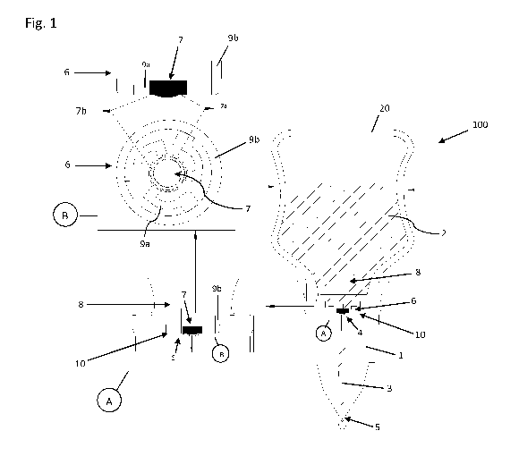
Figure 1 shows a first embodiment of a dispensing device 100 in accordance
with the present invention that comprises a dispensing head 1 in accordance
with the invention. The entire dispensing device 100 is shown at the right in
Figure 1 in the state in which a metered dispensing of a fluid 2 stored in a
storage container 20 takes place. The storage container 20 is here connected
to a dispensing head 1 in accordance with the invention, for example via a
snap-closure or another mechanical fastening. The dispensing head here has a
dispensing opening 5 via which the liquid preparation 2 can be dispensed. The
dispensing opening 5 communicates via a passage channel 3 with the inlet
opening 4 via which liquid preparation 2 can move from an inner space 8 via
the passage channel 3 in the direction of the dispensing opening 5.
The storage vessel 20 is here in particular formed as a squeeze bottle that
can
be squeezed and thus actuated by pressure (see the arrows shown at the right
in Figure 1).
The valve 6 that can reversibly close the inlet opening 4 of the passage
channel 3 is shown in a detailed embodiment in section A (bottom left of
Figure 1). A further enlarged representation of the valve 6 can be seen in
section B that selectively shows the valve 6 in a lateral sectional drawing
(section B, top) and in a perspective plan view (section B, bottom).
The valve 6 here has a valve body 7 that has two concentric sealing lips 7a,
7b
at its lower side (i.e. at the side facing the inlet opening 4 of the passage
channel 3). The metered volume is first dispensed at a high pressure. After
dispensing the defined volume, the valve 6 is then closed by the increasing
pressure. The valve body 7 is pressed onto the inlet opening 4 of the passage
channel 3, in particular via the sealing lips 7a, 7b, due to the pressure
exerted
on the squeeze bottle and a fluidic closure takes place in which a barrier
that
is temporarily impenetrable for the fluid 2 is formed between the wall of the
dispensing head 1 to which the valve body 7 is pressed and the inlet opening 4
LEGAL 35036019.1 1012855-
277931 KB/sz
Date Recue/Date Received 2020-11-12
CA 03100093 2020-11-12
8
of the passage channel 3. This is unlike conventional squeeze bottle in which
no metered dispensing takes place, but rather the dispensing is only stopped
when the pressure on the squeeze bottle is ended. The dispensing volume can
thus be metered independently of the pressure exerted on the squeeze bottle
and thus always equally.
In the exemplary case of Figure 1, the valve 6 is configured here such that
the
valve body 7 (with the sealing lips 7a, 7b located thereon) is fastened to a
frame 9b via holding arms 9a. All the previously named components form the
valve 6. This valve 6 can be inserted into a reception opening 10 in the
dispensing head 1 provided for the reception of this valve 6 and can be
fastened therein (for example, only via a corresponding dimensional design of
the reception opening 10 in the dispensing head and of the valve 6) without it
being necessary to use additional mechanical means to fasten the valve 6 in
the dispensing head 1.
The dispensing device 100 is shown in Figure 2a as also already shown in
Figure 1. For reasons of clarity, all the reference symbols of the components
that are the same per se are not listed in Figure 2. The state is shown in
detail
I in which the valve body 7 is completely pressed onto the inlet opening 4 of
the passage channel 3 and the passage channel 3 is thus closed by the valve
body 7.
Figure 2b shows the state of pressure equalization, i.e. when the dispensing
device 100 is set into a storage state after a dispensing has taken place. The
dispensing device is here placed onto the base of the storage container 20. A
reversible expansion of the squeeze bottle 20 takes place; volume previously
dispensed in the form of liquid 2 is replaced with air here (shown in detail
II)
that can flow into the inner space 8 via the passage channel 3. A pressure
equalization thus takes place in the interior by the sucking in of air. The
position in which the squeeze bottle is located plays no role here.
Figure 3 shows an alternative embodiment of a dispensing head 1 in
accordance with the invention having an alternative valve 6. In the case of
Figure 3, the valve 6 has a valve body 7 at which - otherwise analogously to
the valve 6 in accordance with Figure 1 - two sealing lips 7a and 7b are
LEGAL 35036019.1 1012855-277931 KB/sz
Date Recue/Date Received 2020-11-12
CA 03100093 2020-11-12
9
arranged at the lower side. The valve body 7 additionally has a guide
prolongation 7c. The valve 6 is here received in a reception opening 10 of the
dispensing head 1 and is vertically movable there (indicated to the arrows by
the arrow v). The reception opening 10 has a boundary 11 that can, for
example, be configured in the form of a projection and/or of a constriction of
the opening 10 to prevent the valve 6 from falling out of the reception
opening 10 in the operating state or in the state in which the metering device
is placed upside down on the base of the squeeze bottle 20.
The valve body 7 is dimensioned here such that fluid 2 can flow in the
direction of the inlet opening 4 or the passage channel 3 between the wall of
the reception opening 10 and the tips of the valve body 7 at any time.
The guide prolongation 7c shown in the exemplary case of Figure 3 is
configured here in a manner to secure the valve 6 in a horizontal position
with
respect to the passage channel 3 or the inlet opening 4 so that a reliable
sealing of the inlet opening 4 is always ensured via the sealing lips 7a, 7b.
The function of the valve 6, in particular as regards the pressures for the
reversible closing of the inlet opening 4, is identical to the embodiment of
Figure 1 in all the other respects.
Figure 4a shows the dispensing device 100 - in an analog manner to Figure
2a - in a state I in which the inlet opening 4 of the passage channel 3 is
completely closed via the valve 6. This state occurs when pressures are
exerted on the squeeze bottle 20 reaching to the rear.
Figure 4b shows the dispensing device 100 in a state II in which previously
dispensed volume of the liquid preparation 2 is replaced with air L and the
squeeze bottle 20 returns to the original state (see indicated arrows).
LEGAL 35036019.1 1012855-
277931 KB/sz
Date Recue/Date Received 2020-11-12