Note: Descriptions are shown in the official language in which they were submitted.
Attorney Ref.: 13 32P002CA01
ELECTRICALLY ISOLATED ADAPTER
TECHNICAL FIELD
Example embodiments generally relate to hand tools and, in particular, relate
to an
adapter tool that is desirable for use in environments where work occurs
around electrically
charged components.
BACKGROUND
Socket tools, such as socket wrenches, are familiar tools for fastening nuts
and other
drivable components or fasteners. The sockets of these tools are generally
removable heads
that interface with a drive square on the socket wrench on one side and
interface with one of
various different sizes of nut or other fastener on the other side. The sizes
of the interface at
either end of the socket (i.e., the size of the receivers for both receiving
the drive square and
receiving the nut or fastener) are typically fixed at standard sizes.
Similarly, the size of the
drive square on each individual socket wrench is also fixed at a standard
size.
Some users may have a vast array of wrenches and socket sets to ensure that a
matching
drive square is available for each socket and wrench combination. However,
many users prefer
to employ an adapter (or adapter set) to allow a smaller number of individual
pieces to be
owned to still effectively utilize the range of sockets and/or wrenches that
such users may own.
These adapters may also, in some cases, extend the effective length of the
socket along the axis
of rotation to allow the socket to be used to reach recessed nuts or
fasteners. Regardless of the
specific purpose for use, adapters are popular, and often essential, toolkit
additions for many
users.
Because high torque is often applied through these tools, and high strength
and durability is
desirable, the sockets, wrenches and adapters are traditionally made of a
metallic material such
as iron or steel. However, metallic materials can also corrode or create spark
or shock hazards
when used around electrically powered equipment. In the past, it has been both
possible and
common to coat portions of a metallic socket, wrench or adapter in a material
that is non-
conductive, such material is typically not suitable for coverage of either the
driven end
1
Date Regue/Date Received 2022-05-30
CA 03100287 2020-11-12
WO 2020/005805 PCT/US2019/038668
of the socket/adapter (i.e., the end that interfaces with the wrench) or the
driving end of the
socket/adapter (i.e., the end that interfaces with the nut or other fastener
being tightened by the
socket or the end that interfaces with the socket for the adapter), or the
working end of the
wrench (including especially the drive square, drive hex, or other drive
head). The high torque
and repeated contact with metallic components would tend to wear such
materials away over
time and degrade the performance of the tool. Thus, it is most likely that the
ends of the socket
would remain (or revert to) exposed metallic surfaces so that the socket would
potentially
conduct electricity and be a shock or spark hazard.
Thus, it may be desirable to provide a new design for electrical isolation of
such tools.
BRIEF SUMMARY OF SOME EXAMPLES
Some example embodiments may enable the provision of an adapter that includes
a
driven end and driving end that are electrically isolated. In this regard,
each of the driven end
and the driving end may be formed of separate metallic bodies that are
electrically isolated
from each other via an over-molding process. The metallic bodies may be formed
to be
coextensive along at least a portion of their axial lengths.
In an example embodiment, an electrically isolated adapter is provided. The
adapter
may include a drive body made of first metallic material extending along a
common axis, a
driven body made of a second metallic material extending along the common
axis, and an
isolation assembly formed of insulating material disposed between the drive
body and the
driven body. The drive body may include a drive head configured to interface
with a socket or
fastener. The insulating material has a resistance to electrical current that
is higher than the
resistance to electrical current of at least one of the first metallic
material and the second
metallic material. The driven body may include a drive receiver configured to
interface with a
protrusion of a driving tool. A portion of one of the drive body or the driven
body is received
inside a portion of the other of the drive body or the driven body such that
the drive body and
driven body overlap each other along the common axis.
Another embodiment discloses a driver extension. The driver extension may
include a
head having a first end configured to mate with a driver (e.g. socket wrench,
screwdriver, etc.)
and a second end having a plurality of splines disposed around an outer
circumference of the
second end, the head being made of a first material. The driver extension
further includes a
tail having a third end having an opening and a plurality of trenches disposed
around a
circumference of the open end and a fourth end configured to mate with a
driven body (e.g.
bolt, nut, screw, etc.) the tail being made of a second material. The driver
extension also
2
Attorney Ref.: 13 32P002CAO 1
includes a body made of a material that has a resistance to electrical current
that is
greater than the resistance to electrical current of at least one of the first
material and the second
material, the body being at least partially disposed between the head and the
tail. In this
embodiment the first end is disposed within the opening of the third end.
In another aspect, this document discloses an electrically isolated adapter
comprising:
a drive body made of a first metallic material extending along a common axis,
the drive body
comprising a drive head configured to interface with a socket or fastener; a
driven body made
of a second metallic material extending along the common axis, the driven body
having a drive
receiver configured to interface with a protrusion of a driving tool; and an
isolation assembly
formed of an insulating material disposed between the drive body and the
driven body wherein
the insulating material has a resistance to electrical current that is higher
than the resistance to
electrical current of at least one of the first metallic material and the
second metallic material,
wherein a portion of one of the drive body or the driven body is received
inside a portion of
the other of the drive body or the driven body such that the drive body and
driven body overlap
each other along the common axis, wherein the drive body comprises a drive
body shaft
extending away from the drive head along the common axis, wherein the driven
body
comprises a drive body receiver formed by sidewalls that extend parallel to
the common axis
away from a base portion, wherein the drive body shaft is received inside the
drive body
receiver with the isolation assembly separating the drive body from the driven
body, wherein
the drive body shaft includes a plurality of splines that extend parallel to
the common axis with
a corresponding plurality of trenches formed therebetween, wherein the
sidewalls comprise
ridges formed inwardly from the sidewalls toward the common axis and extending
parallel to
the common axis, the ridges having recesses formed therebetween.
In another aspect, this document discloses a driver extension comprising: a
head having
a first end configured to mate with a driver and a second end having a
plurality of splines
disposed around an outer circumference of the second end, the head being made
of a first
material; a tail having a third end having an opening and a plurality of
trenches disposed around
a circumference of the open end and a fourth end configured to mate with a
driven body, the
tail being made of a second material; a body made of a material that has a
resistance to electrical
current that is greater than the resistance to electrical current of at least
one of the first material
and second material, the body being at least partially disposed between the
head and the tail;
wherein the first end is disposed within the opening of the third end; wherein
the driver
extension further comprises a second plurality of trenches disposed on the
outer circumference
3
Date Regue/Date Received 2022-05-30
Attorney Ref.: 1332P002CA01
of the second end, the second plurality of trenches and the plurality of
splines being
cooperatively engaged around the outer circumference of the second end.
BRIEF DESCRIPTION OF THE SEVERAL VIEWS OF THE DRAWING(S)
Having thus described some example embodiments in general terms, reference
will now
be made to the accompanying drawings, which are not necessarily drawn to
scale, and wherein:
FIG. 1 illustrates a perspective view of an electrically isolated adapter
according to an
example embodiment;
FIG. 2 illustrates an exploded perspective view of the adapter according to an
example
embodiment;
FIG. 3 illustrates a cross section view of the adapter taken along the axis of
rotation of
the adapter according to an example embodiment;
FIG. 4 illustrates a front perspective view of a driven body of the adapter
according to
an example embodiment;
FIG. 5 is a rear perspective view of the driven body according to an example
embodiment;
FIG. 6 is a front perspective view of a drive body of the adapter according to
an example
embodiment;
FIG. 7 is a front view of the drive body of the adapter according to an
example
embodiment;
FIG. 8 illustrates another front perspective view of the driven body according
to an
example embodiment;
FIG. 9 is a perspective view of the drive body inserted into the driven body
prior to
injection of insulating material therebetween according to an example
embodiment;
FIG. 10 is a cross section view taken through a midpoint of the adapter along
a plane
that is substantially perpendicular to the axis of rotation of the adapter
according to an example
embodiment;
FIG. 11 illustrates an exploded perspective view of an adapter from a front
perspective
according to an example embodiment;
FIG. 12 illustrates an exploded perspective view of an adapter from a rear
perspective
according to an example embodiment;
3a
Date Regue/Date Received 2022-05-30
CA 03100287 2020-11-12
WO 2020/005805 PCT/US2019/038668
FIG. 13 illustrates an isolated front perspective view of a drive body of the
adapter
according to an example embodiment;
FIG. 14 illustrates an isolated rear perspective view of the drive body of the
adapter
according to an example embodiment;
FIG. 15 illustrates an isolated, front perspective view of a driven body of
the adapter
according to an example embodiment;
FIG. 16 illustrates an isolated view of an isolation assembly of the adapter
perpendicular to its longitudinal axis from a rear perspective and in cross
section taken through
a center of the isolation assembly according to an example embodiment;
FIG. 17 illustrates an isolated view of an isolation assembly of the adapter
perpendicular to its longitudinal axis from a front perspective and in cross
section taken through
the center of the isolation assembly according to an example embodiment;
FIG. 18 illustrates a fully assembled, perspective view of another adapter
according to
an example embodiment;
FIG. 19 illustrates a cross section view of the adapter taken through a center
thereof
perpendicular to the longitudinal axis of the adapter according to an example
embodiment;
FIG. 20 illustrates a cross section of the adapter view taken along the
longitudinal axis
according to an example embodiment;
FIG. 21 illustrates an exploded rear perspective view of the adapter according
to an
example embodiment;
FIG. 22 illustrates an exploded front perspective view of the adapter
according to an
example embodiment;
FIG. 23 illustrates an isolated perspective view of a drive body of the
adapter according
to an example embodiment;
FIG. 24 illustrates an isolated perspective view of a driven body of the
adapter
according to an example embodiment;
FIG. 25 illustrates the drive body and driven body assembled prior to
injection molding
of an isolation assembly 330 according to an example embodiment;
FIG. 26 illustrates an alternative isolated, front perspective view of the
driven body of
the adapter according to an example embodiment;
FIG. 27 illustrates a front view of the drive body in isolation according to
an example
embodiment;
FIG. 28 illustrates an isolated rear perspective view of the isolation
assembly of the
adapter according to an example embodiment;
4
CA 03100287 2020-11-12
WO 2020/005805 PCT/US2019/038668
FIG. 29 illustrates an isolated front perspective view of the isolation
assembly of the
adapter according to an example embodiment;
FIG. 30 is a cross section view of the isolation assembly taken at a center
thereof and
perpendicular to the common axis according to an example embodiment;
FIG. 31 illustrates a front perspective view of a cross section taken through
a center of
the isolation assembly along the common axis according to an example
embodiment; and
FIG. 32 illustrates a side view of the same cross section shown in FIG. 31
according to
an example embodiment.
DETAILED DESCRIPTION
Some example embodiments now will be described more fully hereinafter with
reference to the accompanying drawings, in which some, but not all example
embodiments are
shown. Indeed, the examples described and pictured herein should not be
construed as being
limiting as to the scope, applicability or configuration of the present
disclosure. Rather, these
example embodiments are provided so that this disclosure will satisfy
applicable legal
requirements. Like reference numerals refer to like elements throughout.
Furthermore, as used
herein, the term "or" is to be interpreted as a logical operator that results
in true whenever one
or more of its operands are true. As used herein, operable coupling should be
understood to
relate to direct or indirect connection that, in either case, enables
functional interconnection of
components that are operably coupled to each other.
As indicated above, some example embodiments may relate to the provision of
electrically isolated socket tools that can be used in proximity to powered
components or
components that have an electrical charge. In some cases, the user can safely
work on or around
such components or systems without having to de-energize the system. The
electrical isolation
provided may minimize the risk of surge currents traveling from a fastener to
a socket tool
(such as a socket wrench or a power tool that drives sockets). Particularly
for power tools that
include electronic components that log data about power tool usage, the
isolated socket can
protect the electronic components and valuable computer data such as recorded
torque
information on fasteners and run-down count history for estimating power tool
life.
Past efforts to provide isolation involving driving adapters or sockets have
involved
two metallic bodies that are separated longitudinally, and that have used
fiber wound (or
braided) composite tubes or injection molded or compression molded short fiber
composites
such as glass filled Nylon to hold the two metallic bodies apart and transfer
torque. These
designs tend to have long lengths and large diameters. The long lengths are
typically due to
CA 03100287 2020-11-12
WO 2020/005805 PCT/US2019/038668
the gap provided between the bodies, and the large diameters are due to the
large volume of
composite material needed to allow torque transfer without breaking the
composite material
between the bodies or that engages the bodies. The resulting structure
includes no overlapping
of the metallic bodies along any portion of the axis of the adapter or socket.
Example embodiments provide the driven end and the drive end to include
metallic
bodies that are configured to overlap each other over at least a portion of
their respective
lengths. In particular, the metallic body on the drive end (e.g., the drive
body) and the metallic
body on the driven end (e.g., the driven body) may each include corresponding
structures that
extend parallel to each other and to the axis to mutually reinforce each other
in an overlap
region with insulating material being interposed between the drive and driven
bodies. As a
result, metallic materials extend over the full length of the adapter so that
the diameter of the
adapter can be substantially smaller than conventional adapters. Additionally,
since the drive
and driven bodies overlap along the axial lengths thereof, there is no need to
define a substantial
gap therebetween along the longitudinal (or axial) length of the adapter, and
the overall length
of the adapter can be reduced if desired. Lengths of adapters made according
to example
embodiments can therefore be selected based on specific applications and
without regard to
defining a gap between the bodies. Meanwhile, the diameters of such adapters
can be about
equal to (or even less than) twice the length of the drive head (e.g., drive
square, drive hex,
etc.).
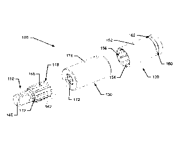
FIG. 1 illustrates a perspective view of an electrically isolated adapter 100
according to
an example embodiment, and FIG. 2 illustrates an exploded perspective view of
the adapter
100. FIG. 3 illustrates a cross section view of the adapter 100 taken along
the axis of rotation
of the adapter (which is also the longitudinal axis of the adapter 100). FIGS.
4-8 illustrate
various isolated views of a drive body 110 and driven body 120 of the adapter
100 to further
facilitate an understanding of how an example embodiment may be structured.
FIG. 9 is a
perspective view of the drive body 110 inserted into the driven body 120 prior
to injection of
insulating material therebetween. FIG. 10 is a cross section view taken
through a midpoint of
the adapter 100 along a plane that is substantially perpendicular to the axis
of rotation of the
adapter.
Referring to FIGS. 1 to 10, in addition to the drive body 110 and the driven
body 120,
the adapter 100 may include an isolation assembly 130 that is configured to
separate the drive
body 110 from the driven body 120 and also cover substantially all of the
lateral edges of the
driven body 120. The drive body 110 and driven body 120 may each be made of
steel or
another rigid metallic material. Steel or other rigid metals generally have a
low resistance to
6
CA 03100287 2020-11-12
WO 2020/005805 PCT/US2019/038668
electrical current passing therethrough. The drive body 110 and the driven
body 120 may be
designed such that, when assembled into the adapter 100, the drive body 110
and the driven
body 120 do not contact each other. The drive body 110 and the driven body 120
may be
oriented such that a drive end 112 of the drive body 110 and a driven end 122
of the driven
body 120 face in opposite directions. Axial centerlines of each of the drive
body 110 and the
driven body 120 are aligned with each other and with a longitudinal centerline
of the adapter
100.
The drive body 110 may include a drive head 140, which faces away from the
driven
body 120 and protrudes out of the isolation assembly 130. The drive head 140
may be
configured to interface with a socket, a fastener, or any other component
having a receiving
opening that is complementary to the shape of the drive head 140. In this
example, the drive
head 140 is a drive square. However, other shapes for the drive head 140 are
also possible, as
will be demonstrated below. In some embodiments, a ball plunger may be
disposed on a lateral
side of the drive head 140 to engage with a ball detent disposed on a socket
or other component.
The drive body 110 may also include drive body shaft 142 that may be
configured to
extend rearward from the drive head 140. Both the drive head 140 and the drive
body shaft
142 may share a common axis 144, which is also the rotational and longitudinal
axis of the
drive body 110 and the adapter 100. As can be appreciated from FIGS. 2, 6 and
7, the drive
body shaft 142 may be a splined shaft. As such, for example, a plurality of
splines 146 (e.g.,
longitudinally extending ridges, protrusions or teeth) may extend parallel to
the common axis
144 along a periphery of the drive body shaft 142. Between each of the splines
146, a
longitudinally extending trench 148 may be formed. As shown in FIG. 7, this
example
embodiment includes ten splines 146 and ten trenches 148, but any desirable
number of splines
146 and trenches 148 could be employed in other example embodiments.
As can also be appreciated from FIG. 7, the splines 146 may extend radially
outward
from a cylindrical core of the drive body shaft 142. The cylindrical core
portion of the drive
body shaft 142 may have a diameter that is about equal to a diagonal length
between opposing
corners of the drive head 140. The splines 146 may extend away from the
cylindrical core
portion by between about 5% and 25% of the diameter of the cylindrical core
portion of the
drive body shaft 142, and the diagonal length between opposing corners of the
drive head 140.
Thus, the diameter of the drive body shaft 142 may be no more than 50% larger
than the
diagonal length between opposing corners of the drive head 140 (and in some
cases as little as
10% larger). In this example, the splines 146 and trenches 148 have a
substantially sinusoidal
7
CA 03100287 2020-11-12
WO 2020/005805 PCT/US2019/038668
shape when viewed in cross section. However, the splines 146 and trenches 148
could
alternatively have sharper edges, if desired.
The driven body 120 may take the form of a cylinder that has been hollowed out
to at
least some degree to form a drive body receiver 150. The drive body receiver
150 may be
fonned between sidewalls 152 (which could be considered a single tubular
sidewall) of the
driven body 120 that define the external peripheral edges of the driven body
120 and radially
bound the drive body receiver 150. The sidewalls 152 may extend parallel to
the common axis
144 away from a base portion 153. The sidewalls 152 may have longitudinally
extending ridges
154 that extend inwardly from the sidewalls 152 toward the common axis 144.
The ridges 154
may be separated from each other by longitudinally extending recesses 156. The
ridges 154
and recesses 156 may be equal in number to the number of splines 146 and
trenches 148 of the
drive body 110 and may be formed to be substantially complementary thereto.
However, the
diameter of the drive body receiver 150 may be larger than the diameter of the
drive body shaft
142 so that the ridges 154 remain spaced apart from corresponding portions of
the trenches 148
and the splines 146 remain spaced apart from corresponding portions of the
recesses 156.
In some cases, the driven body 120 may further include an annular groove 160
that may
include a receiver 162 formed in the base portion 153. In this regard, the
annular groove 160
may be formed around a periphery of the base portion 153. The annular groove
160 and/or the
receiver 162 may be used for facilitating affixing the driven body 120 to the
power tool or
wrench that is used to drive the adapter 100 via passing of a pin through the
receiver 162, or
via a ball plunger being inserted into the receiver 162 as described above
from a drive head of
the power tool or wrench. Thus, the receiver 162 may extend through the driven
body 120 (at
the annular groove 160) substantially perpendicular to the common axis 144 of
the adapter 100.
The annular groove 160 may be provided proximate to (but spaced apart from)
the driven end
122. A drive receiver 163 may also be formed in the driven end 122 to receive
the drive head
of the power tool or wrench that operably couples to the adapter 100. In other
words, the drive
receiver 163 may be formed through the base portion 153 along the common axis
144.
When the drive body 110 is inserted into the driven body 120 (as shown in FIG.
9), an
inside surface of the sidewalls 152 may appear corrugated and complementary to
an outside
surface of the drive body shaft 142, which also appears corrugated, but spaced
apart from the
sidewalls 152 by a gap 170. The drive body 110 and the driven body 120 may be
maintained
spaced apart from each other in this manner (such that no portion of either
touches any portion
of the other) while an insulating material (e.g., rubber, plastic, resin, or
other such materials) is
injected therebetween as part of an injection molding operation. The
insulating material has a
8
CA 03100287 2020-11-12
WO 2020/005805 PCT/US2019/038668
high resistance to electrical current passing therethrough; in one embodiment
the resistance to
electrical current of the insulating material is several orders of magnitude
higher than the
resistance to electrical current of stainless steel. The insulating material
may fill the gap 170
and define a corrugated or fluted separator 172 separating the sidewalls 152
from the drive
body shaft 142, and thereby also separating the splines 146 and trenches 148
from the recesses
156 and ridges 154, respectively. The insulating material may entirely fill
the gap 160 and any
other spaces between the drive body 110 and the driven body 120, and may also
be molded
over the outside surface of the sidewalls 152 of the driven body 120 and the
drive end 112.
The driven end 122 could also be covered, although some embodiments (including
this
example) may leave the driven end 122 uncovered. The insulating material may,
once cured,
form the isolation assembly 130. Although outside the scope of the present
disclosure,
additional components may be provided and/or designed to enable retention of
the drive body
110 and driven body 120 relative to each other during the injection molding
process.
Accordingly, the drive body 110 and the driven body 120 may be clamped
effectively in an
injection molding machine during the injection molding process to ensure that
the pressure
stays balanced and the respective parts do not move during the injection
process and result in
uneven thickness of the insulating material.
As can be appreciated from the descriptions above, the isolation assembly 130
may be
defined at least by the fluted separator 172 and an outer cup 174, which may
be substantially
cylindrical in shape extending along the outer edges of the sidewalls 152. The
fluted separator
172 may engage the outer cup 174 at forward most edges (with the driving head
140 being
considered the front for reference) of the fluted separator 172 and the outer
cup 174.
Meanwhile, distal ends of the fluted separator 174 may be joined by a
separation base 176. The
separation base 176 may be a plate shaped portion of the isolation assembly
130 that extends
perpendicular to the common axis 144 and separates the base portion 153 from
the distal end
of the drive body shaft 142. Thus, the outer cup 174 may mate with the fluted
separator 172
such that the fluted separator 172 is essentially inserted into the outer cup
174. The drive body
shaft 142 may be essentially fully encased within the fluted separator 172 and
separation base
176 with only the drive head 140 extending out of the isolation assembly 130.
Meanwhile, the
sidewalls 152 may be fully encased between the fluted separator 172 and the
outer cup 174
such that (due to the further coverage provided by the separation base 176)
effectively an
entirety of the driven body 120 is also nearly fully encased with (in this
example) only the
driven end 122 uncovered. Thus, effectively all of the driven body 120 other
than the driven
end 122 may be encased by the isolation assembly 130.
9
CA 03100287 2020-11-12
WO 2020/005805 PCT/US2019/038668
In an example embodiment, both the drive body 110 and the driven body 120 may
be
made of metallic material (e.g., stainless steel, or other rigid and durable
alloys). By making
the drive body 110 and driven body 120 of metallic material, the drive body
110 and driven
body 120 may each be very durable and able to withstand large amounts of
force, torque and/or
impact even while themselves being relatively thin and short. Meanwhile,
injection-molding
the isolation assembly 130 around and between the drive body 110 and the
driven body 120
using a non-metallic and insulating material may render the drive body 110 and
driven body
120 electrically isolated from each other. Thus, although the advantages of
using metallic
material are provided with respect to the interfacing portions of the adapter
100, the
disadvantages relative to use in proximity to electrically powered or charged
components may
be avoided.
As noted above, the isolation assembly 130 may be formed around the drive body
110
and the driven body 120 by injection molding to securely bond and completely
seal the adapter
100 other than the drive head 140 and the driven end 122. The fluted separator
172 extends
between the sidewalls 152 of the drive shaft body 142, which otherwise overlap
each other
along the common axis 144. This overlap allows the pressure exerted on each of
the ridges
154 of the driven body 120 to be distributed substantially evenly and
transmitted to the splines
146 of the drive body 110 through the fluted separator 172. However, since the
fluted separator
172 is mutually supported on opposing sides thereof (e.g., by the
complementary shapes of the
splines 146 and trenches 148 with the recesses 156 and ridges 154,
respectively) by the
overlapping portions of the drive shaft body 142 and the sidewalls 152, the
fluted separator 172
is not prone to breakage even if the fluted separator 172 is made relatively
thin (e.g., 0.5 mm
to 2 mm). In particular, the width of the fluted separator 172 (measured in
the radial direction)
may be less than the radial length of either or both of the ridges 154 and the
splines 146. In
some cases, the width of the fluted separator 172 may be substantially equal
to the width of the
outer cup 174 (again measured in the radial direction). Accordingly, the
overall diameter and
length of the drive body 110 and the driven body 120 (and correspondingly also
the adapter
100) may be kept substantially smaller than conventional adapters. In
particular, for example,
a length of each of the drive body 110 and the driven body 120 may be between
about three
times and four times a length of the drive head 140. Additionally, a length of
the adapter 100
along the common axis 133 may be between about four times and five times the
length of the
drive head 140. In some cases, a width of the drive body 110 may be less than
50 /0 larger than
a width of the drive head 140, and a width of the adapter 100 may be less than
three times the
width of the drive head 140. In some cases, a maximum diameter of the drive
body shaft 142
CA 03100287 2020-11-12
WO 2020/005805 PCT/US2019/038668
may be greater than a minimum diameter of the driven body 120 over all
portions of the driven
body 120 where there are sidewalls 152. Thus, at each and every radial
distance from the
common axis 133, there is metal from either the drive body shaft 142 or the
sidewalls 152, and
there is also radial overlap of metal from each component in the transition
region defined
between the troughs of the trenches 148 and the recesses 156. In some
embodiments, it may
be advantageous to increase the number of lobes or splines as the size of the
drive head 140 (or
drive body 110) increases. This increase in the number of splines causes an
increase in the
effective radius of torque transfer. Thus, examples described herein will
include 5 lobes for the
3/8" drive head and more lobes for larger drive heads. The sinusoidal shape
and uniform
thickness of the resulting fluted separator 174 may be advantageous as well
because it reduces
stress concentrations.
The general design principles described above in reference to FIGS. 1-10 may
be
applied in other contexts as well. For example, the number, size and shapes of
the
splines/ridges can be altered to suit any desired drive head combination (both
on the adapter
100 and received by the adapter 100). Similarly any size and shape for the
drive heads (both
on the adapter 100 and received by the adapter 100). In this regard, FIGS. 11-
17 illustrate
examples of an alternate drive head shape (namely a hex shaped drive head),
and FIGS. 18-32
illustrate examples of an adapter having an alternative spline/ridge number
and size (which
may correlate to a different drive square size).
Referring now to FIGS. 11-17, an adapter 200 of another example embodiment is
shown. FIGS. 11 and 12 illustrate exploded perspective views of the adapter
200 from front
and rear perspectives. FIGS. 13 and 14 illustrate isolated perspective views
of a drive body
210 of the adapter 200 from front and rear perspectives. FIG. 15 illustrates
an isolated, front
perspective view of a driven body 220 of the adapter 200. FIGS. 16 and 17
illustrate isolated
views of an isolation assembly 230 of the adapter 200 perpendicular to its
longitudinal axis
from rear and front perspectives, respectively, and in cross section taken
through a center of
the isolation assembly 230.
As discussed above, the drive body 210 and the driven body 220 may be
separated from
each other by the isolation assembly 230 that is also configured to cover
substantially all of the
lateral edges of the driven body 220. The drive body 210 and driven body 220
may each be
made of steel or another rigid metallic material to allow for, again, a
relatively short and thin
construction without sacrificing strength. One of the main differences between
the adapter 200
of this example embodiment and the previously discussed adapter 100 is that
drive head 240
has a hex shape instead of a square shape, and the drive receiver 263 formed
through a base
11
CA 03100287 2020-11-12
WO 2020/005805 PCT/US2019/038668
portion 253 of the driven body 220 to receive the drive head of the power tool
or wrench that
operably couples to the adapter 100 is also hex shaped. Otherwise, the drive
body 210 and the
driven body 220 may be shaped and structured generally similar to that of the
prior example.
As such, for example, drive body 210 may also include drive body shaft 242,
which may be
configured to extend rearward from the drive head 240 sharing a common axis
244 with the
drive head 240 (and the driven body 220).
The drive body shaft 242 is also a splined shaft having a plurality of splines
246 that
extend parallel to the common axis 244 along a periphery of the drive body
shaft 242. A trench
248 may also be formed between each of the splines 246. This example
embodiment includes
twelve splines 246 and twelve trenches 248. As can also be appreciated from
FIGS. 13 and 14,
the splines 246 may extend radially outward from a cylindrical core of the
drive body shaft
242, and the cylindrical core may again have a diameter similar to the
diameter of the drive
head 240.
The driven body 220 may take the form of a cylinder that has been hollowed out
to at
least some degree to form a drive body receiver 250 that is formed between
sidewalls 252
(which could be considered a single tubular sidewall) of the driven body 220
to define the
external peripheral edges of the driven body 220 and radially bound the drive
body receiver
250. The sidewalls 252 may include longitudinally extending ridges 254 that
extend inwardly
from the sidewalls 252 toward the common axis 244. The ridges 254 may be
separated from
each other by longitudinally extending recesses 256 or grooves to form a
corrugated or fluted
appearance in cross section. The ridges 254 and recesses 256 may be equal in
number to the
number of splines 246 and trenches 248 of the drive body 210 and may align
therewith after
assembly. However, the diameter of the drive body receiver 250 may be larger
than the
diameter of the drive body shaft 242 so that the ridges 254 remain spaced
apart from
corresponding portions of the trenches 248 and the splines 246 remain spaced
apart from
corresponding portions of the recesses 256 to again form a gap 270
therebetween. During
injection molding, the insulating material may fill the gap 270 and define a
corrugated or fluted
separator 272 separating the sidewalls 252 from the drive body shaft 242, and
thereby also
separating the splines 246 and trenches 248 from the recesses 256 and ridges
254, respectively.
The insulating material may entirely fill the gap 260 and any other spaces
between the drive
body 210 and the driven body 220, and may also be molded over the outside
surface of the
sidewalls 252.
FIGS. 16 and 17 show the fluted separator 272 and an outer cup 274, which may
be
substantially similar to the correspondingly named components described above,
in isolation
12
CA 03100287 2020-11-12
WO 2020/005805 PCT/US2019/038668
from rear and front perspectives and in cross section. The outer cup 274 may
mate with the
fluted separator 272 such that the fluted separator 272 is essentially
inserted into the outer cup
274 between the drive body shaft 242 and the sidewalls 252. The fluted
separator 272 and the
outer cup 274 may form the isolation assembly 230 around the drive body 210
and the driven
body 220 by injection molding to securely bond and completely seal the adapter
200 other than
the drive head 240 (and perhaps also the driven end of the driven body 220).
As noted above,
the fluted separator 272 extends between the sidewalls 252 of the drive shaft
body 242, which
otherwise overlap (and are coaxial with) each other along the common axis 244.
This overlap
allows the pressure exerted on each of the ridges 254 of the driven body 220
to be distributed
substantially evenly and transmitted to the splines 246 of the drive body 210
through the fluted
separator 272. However, since the fluted separator 272 is mutually supported
on opposing
sides thereof (e.g., by the complementary shapes of the splines 246 and
trenches 248 with the
recesses 256 and ridges 254, respectively) by the overlapping portions of the
drive shaft body
242 and the sidewalls 252, the fluted separator 272 is not prone to breakage
even if the fluted
separator 272 is made relatively thin (e.g., 0.5 mm to 2 mm). In this example,
however, it can
be seen that the width of the fluted separator 272 (measured in the radial
direction) is slightly
larger than the radial length of either or both of the ridges 254 and the
splines 246.
Referring now to FIGS. 18-32, an adapter 300 of another example embodiment is
shown. FIG. 18 illustrates a fully assembled, perspective view of the adapter
300. FIG. 19
illustrates a cross section view of the adapter 300 taken through a center
thereof perpendicular
to the longitudinal axis of the adapter 300. FIG. 20 illustrates a cross
section view taken along
the longitudinal axis. FIGS. 21 and 22 illustrate exploded perspective views
of the adapter 300
from front and rear perspectives. FIGS. 23 and 24 illustrate isolated
perspective views of a
drive body 310 and a driven body 320 of the adapter 300 from front
perspectives. FIG. 25
illustrates the drive body 310 and driven body 320 assembled prior to
injection molding of
isolation assembly 330. FIG. 26 illustrates an alternative isolated, front
perspective view of a
driven body 320 of the adapter 300, and FIG. 27 illustrates a front view of
the drive body 310
in isolation. FIGS. 28 and 29 illustrate isolated views of the isolation
assembly 330 of the
adapter 300 from rear and front perspectives, respectively. FIG. 30 is a cross
section view of
the isolation assembly 330 taken at a center thereof and perpendicular to the
common axis 344.
FIG. 31 illustrates a front perspective view of a cross section taken through
a center of the
isolation assembly 330 along the common axis 344, and FIG. 32 illustrates a
side view of the
same cross section.
13
CA 03100287 2020-11-12
WO 2020/005805 PCT/US2019/038668
As was the case relative to the examples described above, the drive body 310
and the
driven body 320 may be separated from each other by the isolation assembly 330
that is also
configured to cover substantially all of the lateral edges of the driven body
320. The drive
body 310 and driven body 320 may each be made of steel or another rigid
metallic material to
enable a relatively short and thin construction without sacrificing strength.
The adapter 300 of
this example embodiment employs a drive head 340 in the form of a drive square
(and a drive
receiver 363 also formed to receive a square). Otherwise, the drive body 310
and the driven
body 320 may be shaped and structured generally similar to that of the prior
examples. As
such, for example, drive body 310 may also include drive body shaft 342, which
may be
configured to extend rearward from the drive head 340 sharing a common axis
344 with the
drive head 340 (and the driven body 320).
The drive body shaft 342 is also a splined shaft having a plurality of splines
346 that
extend parallel to the common axis 344 along a periphery of the drive body
shaft 342. A trench
348 may also be formed between each of the splines 346. This example
embodiment includes
five splines 346 and five trenches 348. The splines 346 may extend radially
outward from a
cylindrical core of the drive body shaft 342, and the cylindrical core may
again have a diameter
similar to the diameter of the drive head 340 measured between opposing
corners thereof. In
some cases, each of the splines 346 may extend away from the cylindrical core
portion by
between about 5% and 25% of the diameter of the cylindrical core portion of
the drive body
shaft 342, and the diagonal length between opposing corners of the drive head
340. Thus, the
diameter of the drive body shaft 342 may be no more than 50% larger than the
diagonal length
between opposing corners of the drive head 340 (and in some cases as little as
10% larger).
The driven body 320 may take the form of a cylinder that has been hollowed out
to at
least some degree to form a drive body receiver 350 that is formed between
sidewalls 352
(which could be considered a single tubular sidewall) of the driven body 320
to define the
external peripheral edges of the driven body 320 and radially bound the drive
body receiver
350. The sidewalls 352 may extend parallel to the common axis 344 away from a
base portion
353, which may be a substantially filled cylinder of metallic material. The
sidewalls 352 may
include longitudinally extending ridges 354 that extend inwardly from the
sidewalls 352 toward
the common axis 344. The ridges 354 may be separated from each other by
longitudinally
extending recesses 356 or grooves to form a corrugated or fluted appearance in
cross section.
The ridges 354 and recesses 356 may be equal in number to the number of
splines 346 and
trenches 348 of the drive body 310 and may align therewith after assembly.
However, the
diameter of the drive body receiver 350 may be larger than the diameter of the
drive body shaft
14
CA 03100287 2020-11-12
WO 2020/005805 PCT/US2019/038668
342 so that the ridges 354 remain spaced apart from corresponding portions of
the trenches 348
and the spines 346 remain spaced apart from corresponding portions of the
recesses 356 to
foini a gap 370 therebetween. An end of the drive body shaft 342 is also
spaced apart from the
base portion 353 so that during injection molding, the insulating material may
fill the gap 370
and define a corrugated or fluted separator 372 separating the sidewalls 352
from the drive
body shaft 242, and thereby also separating the splines 346 and trenches 348
from the recesses
356 and ridges 354, respectively. The insulating material may entirely fill
the gap 370 and any
other spaces between the drive body 310 and the driven body 320, and may also
be molded
over the outside surface of the sidewalls 352.
FIGS. 28-32 show the fluted separator 372 and an outer cup 374, which may be
substantially similar to the correspondingly named components described above,
in isolation
from various different perspectives. Meanwhile, distal ends of the fluted
separator 374 may be
joined by a separation base 376. The separation base 376 may be a plate shaped
portion of the
isolation assembly 330 that extends perpendicular to the common axis 344 and
separates the
base portion 353 from the distal end of the drive body shaft 342. Thus, the
outer cup 374 may
mate with the fluted separator 372 such that the fluted separator 372 is
essentially inserted into
the outer cup 374. The drive body shaft 342 may be essentially fully encased
within the fluted
separator 372 and separation base 376 with only the drive head 340 extending
out of the
isolation assembly 330. Meanwhile, the sidewalls 352 may be fully encased
between the fluted
separator 372 and the outer cup 374 such that (due to the further coverage
provided by the
separation base 376) effectively an entirety of the driven body 320 is also
nearly fully encased.
As noted above, the fluted separator 372 extends between the sidewalls 352 of
the drive
shaft body 342, which otherwise overlap (and are coaxial with) each other
along the common
axis 344. This overlap allows the pressure exerted on each of the ridges 354
of the driven body
320 to be distributed substantially evenly and transmitted to the splines 346
of the drive body
310 through the fluted separator 372. However, since the fluted separator 372
is mutually
supported on opposing sides thereof (e.g., by the complementary shapes of the
splines 346 and
trenches 348 with the recesses 356 and ridges 354, respectively) by the
overlapping portions
of the drive shaft body 342 and the sidewalls 352, the fluted separator 372 is
not prone to
breakage even if the fluted separator 372 is made relatively thin (e.g., 0.5
mm to 2 mm). In
this example, however, it can be seen that the width of the fluted separator
372 (measured in
the radial direction) is slightly larger than the radial length of either or
both of the ridges 354
and the splines 346.
CA 03100287 2020-11-12
WO 2020/005805 PCT/US2019/038668
The drive heads and drive receivers discussed above may be configured to
engage
components of different shapes including, for example, a 1/4 inch hex drive
head (in FIGS. 11-
17), a 1/2 inch drive square (in FIGS. 1-10), and a 3/8 inch drive square in
FIGS. 18-31.
However, numerous other sizes (and combinations of different sizes between the
drive head
and the drive receiver) are possible in other example embodiments. As such,
for example, the
drive head could be a screw driver head, a bit holder head, or any of a number
of other driving
heads. Thus, an electrically isolated adapter of an example embodiment may
include a drive
body made of first metallic material extending along a common axis, a driven
body made of a
second metallic material extending along the common axis, and an isolation
assembly formed
of insulating material disposed between the drive body and the driven body.
The drive body
may include a drive head configured to interface with a socket or fastener.
The driven body
may include a drive receiver configured to interface with a protrusion of a
driving tool. A
portion of one of the drive body or the driven body is received inside a
portion of the other of
the drive body or the driven body such that the drive body and driven body
overlap each other
along the common axis.
Many modifications and other embodiments of the inventions set forth herein
will come
to mind to one skilled in the art to which these inventions pertain having the
benefit of the
teachings presented in the foregoing descriptions and the associated drawings.
Therefore, it is
to be understood that the inventions are not to be limited to the specific
embodiments disclosed
and that modifications and other embodiments are intended to be included
within the scope of
the appended claims. Moreover, although the foregoing descriptions and the
associated
drawings describe exemplary embodiments in the context of certain exemplary
combinations
of elements and/or functions, it should be appreciated that different
combinations of elements
and/or functions may be provided by alternative embodiments without departing
from the
scope of the appended claims. In this regard, for example, different
combinations of elements
and/or functions than those explicitly described above are also contemplated
as may be set forth
in some of the appended claims. In cases where advantages, benefits or
solutions to problems
are described herein, it should be appreciated that such advantages, benefits
and/or solutions
may be applicable to some example embodiments, but not necessarily all example
embodiments. Thus, any advantages, benefits or solutions described herein
should not be
thought of as being critical, required or essential to all embodiments or to
that which is claimed
herein. Although specific terms are employed herein, they are used in a
generic and descriptive
sense only and not for purposes of limitation.
16