Note: Descriptions are shown in the official language in which they were submitted.
BLOCK HEAT TRANSFER DEVICE HAVING INTERSECTING CHANNELS
SEPARATED BY SUPPORT PILLARS
The invention relates to a device. The device can be in particular a cooling
device for cooling
an object or a heating device for heating an object. In particular, the device
can be a cooling
plate or a heating plate or hot plate. Furthermore, such a device can also be
referred to as a
heat exchanger. Furthermore, the invention relates to a method for producing
such a device.
A heat exchanger which has plates stacked one on top of the other which form a
first and a
second internal fluid path is described in DE 102012202276 Al. The plates and
disk-like
turbulators which are arranged between the plates and provide a turbulent flow
are soldered
together. However, soldering points have the disadvantage that they can become
defective,
whereby the different media can then mix or contamination of the media can
even take place.
This problem does not occur in the case of single-part or single-piece heat
exchangers which
can also be referred to as monoblock heat exchangers.
WO 2009/136277 Al discloses a cooling plate for absorbing heat. This cooling
plate is a
monoblock haying an inlet opening and an outlet opening to allow the flow of a
cooling fluid
therethrough. This fluid flows through a channel system having channels which
are
configured as blind holes. Although the blind holes are arranged partially at
a right angle to
one another, the flow of the fluid will be substantially laminar. The ends of
the blind holes
are closed with plugs.
WO 2017/053184 Al describes a monoblock heat exchanger which is produced by an
additive manufacturing method, in which in particular a 3D printer can be
used. A further
monoblock heat exchanger which is likewise produced by such a method is
described in WO
2016/057443 Al. In order to generate a turbulent flow of liquid used for
transferring heat,
provision is made for this liquid to flow in a zigzag or sawtooth pattern.
1
Date Recue/Date Received 2021-06-09
WO 2011/115883 A2 discloses a single-piece heat exchanger which has channel
systems for
different liquids comprising channels which branch and have diameters of a
size variable
over their length. The channels or channel systems are open at two ends. In
order to produce
the heat exchanger, layer production is provided e.g. by means of selective
laser melting. In
these channel systems, the liquids are assumed to flow in a laminar manner.
Turbulators are
not provided.
A heat exchanger comprising honeycombed flow gaps is described in DE 10305031
Al. The
heat exchanger has a heat transfer element which is produced from an aluminium
alloy in the
extrusion process. The flow gaps have turbulence generators which can be an
insert element
in the shape of a cross or double-cross. The ends of the heat transfer element
are each
connected to an end piece specifying the flow channels and having inlet and
outlet openings.
A device of the type in question is described in EP 0658737 A2. This is a heat
exchanger
which has a monoblock consisting of ceramic material with at least two channel
systems.
The channels of one channel system can cross with the channels of the other
channel system
in terms of arrangement. It is not possible to mix the media by reason of the
geometric
arrangement of the channels. The channels are bores which are open at both
ends, wherein a
plate is provided for closing purposes. The channel systems have a cross-
section in the form
of an elongate slot, wherein walls having overlapping circular arcs are formed
through the
bores. Turbulators are not provided in this heat exchanger block.
The object of the invention is to provide a device of the type in question, in
which a turbulent
flow of the medium is generated very effectively. Furthermore, it is an object
of the
invention to provide a method for producing such a device.
The device has at least one flow chamber which is provided to allow the flow
of a medium therethrough
and has an inlet opening and an outlet opening. The flow chamber is arranged
in a single-piece block
element which can also be referred to as a monoblock element. It has at least
in part a diathennal wall and
so the medium can absorb or release thermal energy or heat energy through this
wall. The medium can be
in particular gas or liquid. The flow chamber is formed form a plurality of
first
2
Date Recue/Date Received 2021-06-09
CA 03100303 2020-11-13
channels and a plurality of second channels which are arranged in the block
element. The first
channels are spaced apart from one another and extend straight and in parallel
with one
another. The second channels are spaced apart from one another and extend
straight and in
parallel with one another. Both the first and the second channels each have
two ends and are
closed at least at one of the two ends.
The second channels extend at an angle to the first channels such that the
first and the second
channels cross. Between four crossing points of two adjacent first and two
adjacent second
channels, support pillars are located within the flow chamber formed by the
channels. These
support pillars have over their height or length a cross-section in the shape
of a parallelogram.
This shape can also be referred to as a rhomboid or as being diamond-like.
Since the flow
chamber is formed from a row of crossing, straight channels which pass through
one another
at their crossing points, it could also be referred to as a channel system.
Here, the support
pillars are referred to as part of the respective flow chamber. The flow
chamber is thus
characterised in that a plurality of such support pillars are arranged within
the flow chamber
apart from chamber edge regions, wherein the support pillars extend between
two mutually
opposite walls of the flow chamber.
The multiplicity of regularly arranged support pillars ensures that the flow
of the medium
through the flow chamber is generally not laminar but instead is turbulent.
Furthermore, the
support pillars allow the block element and thus the device to have a high
pressure resistance.
The pressure resistance is produced by the large number of support surfaces
which are
provided by the parallelogram-shaped cross-sections of the support pillars.
The support
surfaces support opposite walls of the flow chamber against one another and
hold them
together. The device in accordance with the invention can have e.g. a pressure
resistance of
150 bar. By reason of this high pressure resistance, the flow rate of the
medium can be
relatively high, whereby a turbulent flow is more likely to occur, than at a
low rate.
Preferably, the first channels have a uniform cross-section over their length
apart from their
end regions, when the channels are considered in their own right and the
points at which they
cross with the second channels are not taken into consideration. In other
words, this means
3
Date Recue/Date Received 2020-11-13
CA 03100303 2020-11-13
that the channels, when produced as a bore (see below), have the same diameter
over their
length. Preferably, this also applies correspondingly to the second channels.
Preferably, the
first and second channels also have an identical cross-section when compared
with one
another. Then, the cross-sectional surfaces of the support pillars are also
uniform, apart from
support pillars on the edges of the flow chamber. The diameters of the
channels influence the
physical data of the device, such as heat output and pressure drop in the flow
chamber.
If the distances between mutually adjacent first channels and the distances
between mutually
adjacent second channels are also the same and the distances between the first
and the second
channels are the same, the support pillars have a diamond-like cross-section.
The structure of
the flow chamber then has a particularly high degree of regularity, which is
favourable for a
high pressure resistance of the flow chamber and thus also for the generation
of a turbulent
flow.
Provision can also be made that in each case one of the first channels and one
of the second
channels have, at one of their respective two ends, a common channel opening
and this
channel opening is arranged in a side wall of the block element and
constitutes a side wall
opening. The device then has at least one closure means, by means of which the
side wall
openings can be closed in a sealing manner. Preferably, provision is made that
all of these
common channel openings of a flow chamber are located in the same side wall of
the block
element.
The side wall openings easily permit cleaning and visual inspection of the
respective flow
chamber and thus of the device in accordance with the invention. A further
very substantial
advantage of the side wall openings is that the first and second channels can
be a bore. This is
a preferred embodiment and means that the channels have been produced or are
produced by
boring by means of a rotating tool or else also by bore-eroding or laser
boring. In particular,
the production of the channels by means of a rotating tool can be effected
relatively simply in
comparison with the production of a block element having channels which are
closed at their
two ends, wherein namely an additive production method or 3D printing is
required. The
production of the channels by means of a rotating tool is considerably less
complex and
4
Date Recue/Date Received 2020-11-13
CA 03100303 2020-11-13
relatively cost-effective in comparison with the production of channels,
closed at both ends,
by means of an additive manufacturing method. However, on the other hand the
advantages
provided by the use of a single-piece block element are retained (see above),
namely that no
soldering points, welding seams or seals are provided between components of a
flow chamber
system. Therefore, it is not possible to mix different media if a plurality of
chambers are
provided (see below). The omission of seals, in particular also dual seals, in
relation to the
arrangement of flow chambers means that no sealing grooves, no adhesion or
positioning of
seals are required and tension forces are omitted. Furthermore, the block
element is very
capable of performing an internal movement in the form of expansion or
contraction by
reason of temperature changes.
By reason of the crosswise arrangement of the first and second channels, the
two end regions
of the arrangement of the side wall openings can also have those openings
which do not
constitute a common side wall opening but instead constitute only the channel
opening of a
first or a second channel.
The first and second channels can have a round cross-section, preferably they
are circular.
Then, even though the support pillars have curved lateral surfaces, they have
a parallelogram-
shaped cross-section over their height.
Provision can be made that each side wall opening has a thread which serves to
fasten a plug
screw in order to close the side wall opening in a sealing manner. The plug
screw can be a
hexagon socket screw having a seal, such as an 0-ring. By reason of the
inventive
arrangement of the first and second channels, a first and a second channel can
be closed at the
same time using a plug screw. The plug screws can be standard parts and
provide a reliable
seal. If necessary, they can be quickly replaced. Sealing materials which can
be used for plug
screws are e.g. nitrile rubber (NBR), ethylene propylene diene rubbers (EPDM)
or Viton. Plug
screws provide a reliable seal and ensure a uniform distribution of forces to
a seal.
Furthermore, they are very capable of also performing an above-described
internal movement
of the block element.
5
Date Recue/Date Received 2020-11-13
CA 03100303 2020-11-13
The side wall openings can initially be somewhat elliptical by reason of their
oblique
arrangement with respect to the longitudinal axis of a channel having a
circular cross-section
in the production process. Therefore, provision can be made that this
elliptical shape is bored
prior to the procedure of cutting the thread into a circular shape.
.. The side wall openings can also be closed by a cover in the form of a
closure strip or closure
plate which sealingly covers all of the channel openings of a flow chamber or
all of the
channel openings in a side wall together.
The first and second channels can also cross at an angle of less than 90
degrees, preferably at
an angle of 45 to 75 degrees and more preferably at an angle of 55 to 65
degrees.
In particular, provision can be made that the value of the angle of the first
and second
channels with respect to the side wall of the block element is the same and is
also referred to
hereinafter as the setting angle. Such symmetry of the setting angles with
respect to the side
wall can provide a particularly high degree of regularity in the flow chamber.
The setting
angle likewise influences the physical data of the device, such as heat output
and pressure
drop in the flow chamber.
The device in accordance with the invention can have a flow chamber which is
provided to
allow the flow of a heat-releasing medium therethrough, and can also have a
flow chamber
which is provided to allow the flow of a heat-absorbing medium therethrough.
The respective
diathermal wall of the flow chambers is then a common wall which separates the
two flow
chambers from one another. Instead of the above term "heat", it would also be
possible to use
the term "heat quantity". This embodiment of the device in accordance with the
invention is a
heat exchanger. As described above, it is not possible to mix the different
media, by reason of
the inventive arrangement of the flow chambers in a single-piece or solid
block element. In
the case of the embodiment of a heat exchanger, the above-described high
pressure resistance
of the device in accordance with the invention allows a high system pressure
to prevail within
one flow chamber and allows a considerably lower system pressure to prevail
within an
adjacent flow chamber.
6
Date Recue/Date Received 2020-11-13
CA 03100303 2020-11-13
Preferably, the two flow chambers are arranged such that in each case a
support pillar of the
first flow chamber and a support pillar of the second flow chamber are
arranged in a
congruent manner. This means that the second flow chamber, rotated quasi
through 180
degrees, is arranged above the first flow chamber and so the support pillars
are arranged
precisely one above the other. This ensures that the block element is held
together in a robust
manner.
Of course, a plurality of flow chambers can be provided to allow the flow of
the heat-
releasing medium therethrough and a plurality of flow chambers can be provided
to allow the
flow of the heat-absorbing medium therethrough, wherein the flow chambers are
arranged in
an alternating manner.
The transfer of heat can be particularly effective by virtue of the fact that
the inlet openings
and the outlet openings of the at least two flow chambers are arranged such
that the heat-
releasing medium and the heat-absorbing medium flow in counterflow to one
another through
the flow chambers. Preferably, all of the flow chambers for the heat-releasing
medium and all
of the flow chambers for the heat-absorbing medium each have a common inlet
opening and a
common outlet opening.
Preferably, provision is made that all of the channel openings of the at least
one flow chamber
for a heat-releasing medium are arranged in the same side wall of the block
element and all of
the channel openings of the at least one flow chamber for a heat-absorbing
medium are
arranged in an opposite side wall of the block element. In this manner, two
adjacent flow
chambers can be located relatively closely against one another or have a
relatively thin wall
which separates the two chambers from one another. In this manner, effective
heat transfer
and a compact construction of the block element can be achieved.
Flow chambers which are provided for different media can have different cross-
sectional
surfaces. Different cross-sectional surfaces can be easily achieved by virtue
of the fact that the
diameters of the channels are selected to be different from one another
compared with two
flow chambers. The first and second channels of each same flow chamber can
have identical
7
Date Recue/Date Received 2020-11-13
cross-sections. In particular, in this manner the flow chambers can also have
different
volumes in dependence upon the different media. This is practical because
different media
regularly have different viscosities.
At two end sides, the block element can have in each case one or a plurality
of threads
which are used for fastening the block element to another component.
Various materials can be used as the material from which the block element is
produced. In
particular, the block element can be produced from an aluminium alloy. It is
cost-effective
and is very suitable for producing the channels by means of a rotating tool.
The block
element can undergo passivation, coating and/or surface treatment and in
particular both
externally and internally.
The advantages achieved in connection with the method are described above.
The invention will be explained in greater detail hereinafter with reference
to an
exemplified embodiment, wherein reference is made to the figures. In the
figures:
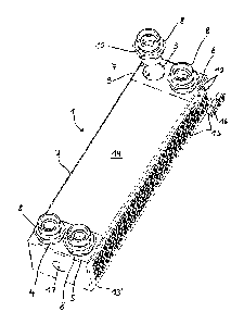
Figure 1 shows a perspective view of a device in accordance with the invention
which is a
heat exchanger,
Figure 2a shows a cross-sectional surface of a flow chamber of the heat
exchanger of figure
1,
Figure 2b shows a side view of the flow chamber of figure 2a before common
channel
openings have been provided with threads,
Figure 3 shows a detail of the cross-sectional surface of figure 2a,
Figure 4a shows a right side view of a single-piece block element of the heat
exchanger of
figure 1,
Figure 4b shows a left side view of a single-piece block element of the heat
exchanger of
8
Date Recue/Date Received 2021-06-09
CA 03100303 2020-11-13
figure 1,
Figure 5 shows a plan view of the block element of figure 1, wherein the
arrangement of the
flow chambers is illustrated,
Fig. 6 shows a sectional view along the sectional line VI-VI in figure 5,
Figure 7 shows a sectional view along the sectional line VII-VII of figure 5,
Fig. 8 shows a partial region C of figure 5.
In the figures, like features are designated in part by like reference signs.
The heat exchanger
is designated by the reference sign 1 and has a single-piece aluminium block
element 2 which
is produced preferably from AlMgSil and has good conductivity. The block
element 2 has an
.. inlet opening 3 and an outlet opening 4 for a first medium, and furthermore
has an inlet
opening 5 and an outlet opening 6 for a second medium. The media can be in
particular a
liquid or a gas. Furthermore, the heat exchanger 1 has four screw-in fittings
8 which are
screwed by means of a thread 7 into the openings 3 to 6, which have a
corresponding internal
thread 9, using a seal (not shown). Furthermore, the screw-in fittings 8 have
an external thread
10 in order to connect hoses for the media.
The block element 2 has a total of six flow chambers 20 and 20' arranged one
above the other
and of which three are provided to allow the flow of the first medium
therethrough and three
are provided to allow the flow of the second medium therethrough. The flow
chambers 20,
20' are arranged in an alternating manner and so in each case one flow chamber
20 for the
first medium and one flow chamber 20' for the second medium are separated from
one
another by a common wall.
Each flow chamber 20 has a plurality of channel openings 12 and each flow
chamber 20' has
a plurality of channel openings 12' which are each located in one of the two
side walls 13 and
13' of the block element 2. Since the flow chambers 20, 20' are arranged in
parallel with a
surface 14 of the block element 2, a horizontal row of channel openings 12,
12' belongs in
9
Date Recue/Date Received 2020-11-13
CA 03100303 2020-11-13
each case to one of the flow chambers 20, 20'.
In figure 4a, all of the channel openings 12' can be seen in the right side
wall 13' and in figure
4b all of the channel openings 12 can be seen in the left side wall 13. The
channel openings
12 belong to the flow chambers 20 of the first medium and the channel openings
12' belong to
the flow chambers 20' of the second medium. In figure 1, all apart from three
of the channel
openings 12' are closed by means of plug screws which have an 0-ring as a seal
and a
hexagon socket head. For this purpose, each channel opening 12, 12' has a
thread.
At both end sides, the block element 2 has a connecting thread 17 for
fastening the heat
exchanger 1 within an assembly. Figures 2a and 2b show a flow chamber 20' of
the second
medium. A detail of this cross-sectional surface is illustrated in figure 3. A
multiplicity of
support pillars 21 having a diamond-shaped cross-section can be seen. The
support pillars 21
are formed by a multiplicity of circular bores which constitute first channels
22, and by a
multiplicity of circular bores which constitute second channels 23. In figure
3, the channels 22
are illustrated by broken lines which extend along the channel longitudinal
direction. By
reason of the circular cross-section of the respective channel 22, the lowest-
lying extension of
the channel 22 extends along the broken line, wherein the same applies to the
second channels
23. The first channels 22 have a positive setting angle 25 with the side wall
13' and the
second channels 23 have a negative setting angle 25' with the side wall 13' of
the same value.
The arrows 26 designate the width of a first channel 22.
The first and second channels 22, 23 have channel openings 12' which can be
seen in figure
2b and which are common channel openings apart from two outer channel
openings. The plan
view according to figure 2b shows in the centre a support pillar 21 which has
a diamond-
shaped cross-section. The opposite ends 27 of the channels 22, 23 are closed.
In figure 2b, the
channel openings 12' are still in a state before they have been bored into a
circular shape and
provided with a thread, and thus still have a somewhat elliptical shape.
Accordingly, a flow chamber 20 for the first medium is structured, wherein it
is arranged,
rotated through 180 degrees in terms of the arrangement, underneath the flow
chamber 20'
Date Recue/Date Received 2020-11-13
CA 03100303 2020-11-13
and between two flow chambers 20'. The respective support pillars 21 lie
congruently one on
top of the other.
In figure 6, all six flow chambers 20, 20' can be seen in section, wherein
likewise support
pillars 21, of which one is designated by way of example by the reference sign
21, are located
between slightly elliptical sections through the channels 22 or 23, through
which support
pillars 21 can be seen. Channel openings 12' can be seen in the inlet opening
5 and the outlet
opening 6. The second medium flows via the inlet opening 5 into all three flow
chambers 20'
and then flows from said chambers via the outlet opening 6 out of the block
element 2. The
same applies to the inlet opening 3 and the outlet opening 4 with regard to
the first medium,
.. wherein the flow-related connection between the flow chambers 20' and the
outlet opening 6
and between the flow chambers 20 and the inlet opening 3 can be seen in
particular in figure
7.
In figure 8, the line 28 indicates a milled-out portion which serves to
connect the central flow
chamber 20' to the outlet opening 6 in terms of flow.
11
Date Recue/Date Received 2020-11-13
CA 03100303 2020-11-13
List of reference signs
1 heat exchanger 14 surface of 2
2 block element 15 plug screws
3 inlet opening 16 hexagon socket head
4 outlet opening 17 connecting thread
inlet opening 20, 20' flow chambers
6 outlet opening 21 support pillars
7 thread 22 first channels
8 screw-in fitting 23 second channels
9 internal thread 25, 25' setting angle
external thread 26 arrows
12, 12' channel openings 27 closed ends of 22, 23
13, 13' side walls 28 line
12
Date Recue/Date Received 2020-11-13