Note: Descriptions are shown in the official language in which they were submitted.
CURTAIN ROD ASSEMBLY
FIELD
[0001] The present subject matter relates to drapery hardware. More
specifically, the
disclosure relates to a novel curtain rod assembly.
INTRODUCTION
[0002] Curtains and drapes can be hung from curtain rods in a number
of different
ways, including with rings, tabs, or a seemed pocket. One popular style uses
grommets (or
eyelets). Typically, two drapery panels are inserted over the left and right
halves of a curtain
rod with successive grommets passing in alternate directions so that the
drapery panels
undulate over the rod in a corrugated fashion, allowing them to be easily
opened and closed.
[0003] The drapery rod is typically cylindrical, often being formed
of two telescoping
sections so that it can be extended to different lengths so as to cover
windows of differing
widths. The two ends of the drapery rod typically are covered with decorative
finials that can
have a variety of shapes.
[0004] The curtain rod can be mounted to a wall above a window typically by
means
of two or three brackets ¨ for example, one bracket near each end and one
bracket in the
center, such that left and right drapery panels can be pulled open or pulled
closed. The
outermost edges of the panels are typically anchored to the ends of the rod by
means of the
outer-most grommets being blocked by the end brackets that hold the rod in
position.
[0005] While this general configuration is popular, it usually suffers from
light
penetration at the two outer edges of the drapery panels. Such light
penetration can be a
problem for users who want a "black-out" curtain, which is to say a curtain
that is intended to
stop any light from entering a room from outside the window.
[0006] It is known to hang curtains from rods that have a right
angled elbow at either
ends so that the curtain can be pushed against the wall on either side of the
window and
thereby prevent or effectively reduce any light penetration. In some cases,
the elbows include
flanges that mount to a wall. However, a simple elbow does not provide any
anchoring for
the outer edge of the curtain panel, and does not accommodate a decorative
finial.
- 1 -
Date Recue/Date Received 2020-11-23
SUMMARY
[0007] According to one aspect of the present disclosure, a curtain
rod assembly is
provided in which the two ends of the rod have both an elbow component that
can turn
inwardly onto a wall when the rod is fixed above a window and also a straight
component
that extends beyond the elbow component and upon which a finial can be
mounted. Thus, a
curtain rod is provided that has finial ends but that also allows the outer
edge of each curtain
panel to hang closely against the wall on either side of a window thereby
preventing or
effectively reducing light from leaking past the curtain.
[0008] In one example, the present curtain rod is based on a
conventional straight rod
having finials mounted or mountable at either ends. The rod is modified by
mounting tubular
elbow sections on the straight rod near the finial ends. The tubular elbow
sections are
dimensioned to fit closely over the straight rod with the rod passing through
an opening in
the side wall of the elbow section.
[0009] According to another example, the present curtain rod assembly
is based on a
U-shaped black-out curtain rod having integral elbow portions at each end. The
rod is
modified by mounting straight tubular sections near the elbows. The straight
tubular sections
are dimensioned to fit closely over the rod with the terminal leg of the rod's
integral elbow
passing through an opening in the side wall of the straight tubular section.
[0010] According to another aspect of the disclosure, there is
provided a modification
kit for a conventional straight curtain rod having finials mounted or
mountable at either ends.
The kit comprises a pair of tubular elbow sections that can be mounted on the
straight rod
near the finial ends. The tubular elbow sections are dimensioned to fit
closely over the straight
rod with the rod passing through an opening in the side wall of the elbow
section. Once the
pair of tubular elbow sections are mounted to it, the conventional straight
curtain rod has two
ends that have both an elbow component that can turn inwardly onto a wall when
the rod is
fixed above a window and also a straight component that extends beyond the
elbow
component and upon which a finial can be mounted. Thus, a curtain rod is
provided that has
finial ends but that also allows the outer edge of each curtain panel to hang
closely against
the wall on either side of a window thereby preventing or effectively reducing
light from
leaking past the curtain.
- 2 -
Date Recue/Date Received 2020-11-23
[0011] According to another aspect of the disclosure, there is
provided a modification
kit for a U-shaped black-out curtain rod having integral elbow portions at
each end. The kit
comprises a pair of straight tubular sections that can be mounted to the rod
near the elbows.
The straight tubular sections are dimensioned to fit closely over the rod.
Once the pair of
straight tubular sections are mounted to it, the U-shaped black-out curtain
rod has two ends
that have both an elbow component that can turn inwardly onto a wall when the
rod is fixed
above a window and also a straight component that extends beyond the elbow
component
and upon which a finial can be mounted. Thus, a curtain rod is provided that
has finial ends
but that also allows the outer edge of each curtain panel to hang closely
against the wall on
either side of a window thereby preventing or effectively reducing light from
leaking past the
curtain.
DRAWINGS
[0012] In order that the claimed subject matter may be more fully
understood,
reference will be made to the accompanying drawings, in which:
[0013] Figure 1 is a side perspective view of an example of a portion of a
curtain rod
assembly according to the present subject matter with the central component
and one of the
end components of the curtain rod assembly shown separated.
[0014] Figure 2 is an alternative side perspective view of one of the
end components
of the curtain rod assembly of the curtain rod assembly of Figure 1.
[0015] Figure 3 is a side perspective view of curtain rod assembly portion
according
to Figure 1 with the components mounted together.
[0016] Figure 4 is a perspective view of the curtain rod assembly
portion of Figure 1
installed with a grommet-style curtain hanging therefrom.
[0017] Figure 5 is a perspective view of another example of a portion
of a curtain rod
assembly according to the present subject matter with the central component
and one of the
end components of the curtain rod assembly shown separated.
[0018] Figure 6 is a perspective view of another example of a side
perspective view of
the curtain rod assembly of Figure 5 with the components mounted together.
- 3 -
Date Recue/Date Received 2020-11-23
[0019] Figure 7 is a side perspective view of one of the end
components of a curtain
rod assembly similar to the curtain rod assembly of Figure 5.
[0020] Figure 8 is a top perspective view of the curtain rod assembly
end component
of Figure 7.
DESCRIPTION OF VARIOUS EMBODIMENTS
[0021] In the following description, specific details are set out to
provide examples of
the claimed subject matter. However, the embodiments described below are not
intended to
define or limit the claimed subject matter. It will be apparent to those
skilled in the art that
many variations of the specific embodiments may be possible within the scope
of the claimed
subject matter.
[0022] Referring to Figure 1, there is shown a portion of a curtain
rod assembly
according to one embodiment of the present subject matter. The curtain rod
assembly
includes a central component 3 and an elbow component 5, which are shown
separated.
[0023] For example, the central component can include a curtain rod.
The rod can be
straight. The rod can be a telescoping rod. The telescoping rod can have a
plurality of
sections. The sections of the telescoping rod can be configured in a
telescoping arrangement
such that a first portion of the telescoping rod is configured to slide into a
second portion of
the telescoping rod and so on. For example, the curtain rod can define an
axial direction. For
example, in use, when a curtain is mounted on the curtain rod, the curtain can
be slid along
the axial direction.
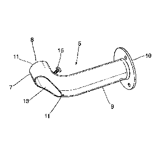
[0024] The elbow component 5 of Figure 1 is further shown in Figure
2. The elbow
component 5 includes a first section 7, a second section 9 and an arc section
11 positioned
between the first section 7 and the second section 9. The elbow component 5
further includes
a first end 8 positioned on the first section 7. The first end 8 of the elbow
component 5 is
adapted to receive a portion of the central component 3. The elbow component 5
further
includes a second end 10 positioned on the second section 9. The second end 10
is adapted
to mount the elbow component 5 to a support surface when installing the rod
assembly.
[0025] The first end 8 of the elbow component 5 defines an opening 11
dimensioned
to receive the central component 3. For example, the opening 11 can snugly fit
the central
component 3. The opening 11 defines a channel within the first section 7. The
channel can
- 4 -
Date Recue/Date Received 2020-11-23
receive and fit closely over part of the central component. The sidewall of
the arc section 11
defines an opening 13 to allow the central component 3 to pass through the
elbow
component. An adjuster 15 (e.g. a screw) can be positioned on a surface
opposing the
opening 13 for fixing the central component 3 within the channel of the first
section 7. The
adjuster 15 can further provide a snug fit between the central component 3 and
the elbow
component 5.
[0026] Referring to Figure 3, the elbow component 5 is shown mounted
on the central
component 3. This can be obtained by passing the central component 3 through
the elbow
component 5 via the opening 11. Then, the central component 3 passes through
the channel
of the first section 7 and exits the elbow component 5 through the opening 13.
For example,
the structure of the elbow component advantageously allows it to blend with
the shape of the
central component 3 such that both of them can accommodate a same grommet-
style
curtain. Figure 4 shows a grommet-style curtain installed on the curtain rod
assembly,
including the central component 3 and the elbow component 5.
[0027] As shown in Figures 1, 3 and 4, a finial 17 can be mounted on the
portion of
central component 3 that extends beyond the elbow component. As shown in
Figure 4, a
curtain rod is provided, such that it a finial end but that also allows the
outer edge of a curtain
panel to hang closely against a wall on one side of a window thereby
preventing or effectively
reducing light from leaking past the curtain.
[0028] Furthermore, a curtain rod can be provided, the curtain rod having
finial ends
and allowing outer edges of a curtain panel to hang closely against a wall on
either side of a
window thereby preventing or effectively reducing light from leaking past the
curtain.
[0029] Referring to Figure 5, there is shown a portion of a curtain
rod assembly
according to one embodiment of the present subject matter. The curtain rod
assembly
includes a central component 53 and a straight tubular section 55, which are
shown
separated.
[0030] The central component 53 includes a U-shaped black-out curtain
rod having
integral elbow portions at one end. For example, the U-shaped black-out
curtain rod can also
have an integral elbow portions 54 at each end. The U-shaped rod can be
modified by
mounting straight tubular sections near the elbows. For example, the straight
tubular sections
- 5 -
Date Recue/Date Received 2020-11-23
are dimensioned to fit closely over the U-shaped rod with the terminal leg of
the rod's integral
elbow passing through an opening in the side wall of the straight tubular
section.
[0031] An embodiment of a straight tubular section 55 is shown in
Figures 5 and 6.
The straight tubular section 55 includes a first end 60 defining a channel 63
through the
tubular section. For example, the surface of the channel 63 can be mounted
over a portion
of the central component 53 proximate the elbow portion 54. For example, the
channel 63
can be open at the first end 60. This allows attachment of the straight
tubular section 55
directly on central component 53 proximate the elbow portion without passing
it through the
elbow portion. A finial 67 can be mounted on a second end of the straight
tubular section 55.
[0032] Another embodiment of a straight tubular section 75 is shown in
Figures 7 and
8. The straight tubular section 75 includes a first end defining an opening 78
and a ring
section 70 for securing the straight tubular section to the U-shaped rod. The
ring section can
prevent the straight tubular section from being falling off the central
component when
attachment between the straight tubular section and the central component is
loose.
[0033] The ring section 70 leads to a channel 73 defined through the
tubular section
75. A portion of the channel can be open to facilitate mounting of the
straight tubular section
75 over a U-shaped curtain rod. For example, the straight tubular section 75
can be mounted
over a U-shaped rod by passing the ring portion through the elbow portion of
the rod. A finial
77 can be mounted on a second end of the straight tubular section 75.
[0034] The curtain rod, the elbow component, the straight tubular section
and the finial
may be made from any suitable materials such as plastics, metals (e.g.
aluminum, steel,
etc.), polymeric materials (e.g. polyethylene, polypropylene, nylon and the
like).
[0035] According to one embodiment, a modification kit for a
conventional straight
curtain rod having finials mounted or mountable at either ends is provided.
The kit can include
a pair of tubular elbow sections that can be mounted on the straight rod near
the finial ends.
The tubular elbow sections are dimensioned to fit closely over the straight
rod with the rod
passing through an opening in the side wall of the elbow section. Once the
pair of tubular
elbow sections are mounted to it, the conventional straight curtain rod has
two ends that have
both an elbow component that can turn inwardly onto a wall when the rod is
fixed above a
window and also a straight component that extends beyond the elbow component
and upon
- 6 -
Date Recue/Date Received 2020-11-23
which a finial can be mounted. Thus, a curtain rod is provided that has finial
ends but that
also allows the outer edge of each curtain panel to hang closely against the
wall on either
side of a window thereby preventing or effectively reducing light from leaking
past the curtain.
[0036] According to one embodiment, a modification kit for a U-shaped
black-out
curtain rod having integral elbow portions at each end is provided. The kit
includes a pair of
straight tubular sections that can be mounted to the rod near the elbows. The
straight tubular
sections are dimensioned to fit closely over the rod. Once the pair of
straight tubular sections
are mounted to it, the U-shaped black-out curtain rod has two ends that have
both an elbow
component that can turn inwardly onto a wall when the rod is fixed above a
window and also
.. a straight component that extends beyond the elbow component and upon which
a finial can
be mounted. Thus, a curtain rod is provided that has finial ends but that also
allows the outer
edge of each curtain panel to hang closely against the wall on either side of
a window thereby
preventing or effectively reducing light from leaking past the curtain.
[0037] It will be appreciated by those skilled in the art that
although the above
alternative embodiments have been described in some detail many modifications
may be
practiced without departing from the claimed subject matter.
- 7 -
Date Recue/Date Received 2020-11-23