Note: Descriptions are shown in the official language in which they were submitted.
CA 03100578 2020-11-17
1
Test bottle protocol method
The present application concerns a method for checking a container inspection
system
and a test container used in this method.
According to the state of the art, reliability tests for test devices, e.g.
those for empty
beverage bottles, so-called empty bottle inspectors, are carried out in such a
way that a series
of test bottles is prepared, each of which has one or more defects or test
characteristics. The
test bottles are then placed in the bottle flow at certain time intervals,
e.g. every half hour, or
after a certain number of bottles, e.g. 50,000 bottles. If all test bottles
are detected as defective,
the empty bottle inspector is assumed to function properly.
After inspection, the bottles that are identified as defective are separated
from the bottle
flow by automatic rejection devices. The system must be able to identify test
bottles even if the
empty bottle inspector is not working properly and should overlook a test
feature of a test bottle.
In today's beverage and food industry, containers are transported with a
throughput of up
to 90,000 bottles per hour. For this reason, the time span available for
inspecting the containers
is very limited. In order to guarantee a reliable procedure for the inspection
of bottle inspection
systems under these conditions, it is known from DE 299 10 452 U1, for
example, that test
bottles are equipped with a concentric transponder containing a code number
for the clear
identification of the test bottle. The system has an additional detection
device which is
exclusively designed to read the transponder of the test bottles. The
additional detection device
complicates the design of such bottle inspection systems and it would
therefore be desirable to
provide a test bottle protocol method that does not require special additional
detection devices
that are only needed for test bottle detection.
DE 10 2012 204 277 Al also describes a method and a device in which test
bottles are
provided with a special multidimensional code. The multidimensional code is
read optically by a
separate reading device. The reading device can be a scanner or similar and is
exclusively
intended to read the multidimensional code of the test bottles. However, this
additional reading
device again complicates the design of such bottle inspection systems.
The task of the present invention is to provide a reliable method by which
test containers
can be reliably detected by a container inspection system without the need for
an additional
detection device or reading device which is exclusively used for reading the
test bottle marking.
Date Regue/Date Received 2020-11-17
2
Furthermore, the task of the present invention is to provide a reliable method
with which test
containers can be reliably detected by a container inspection system, whereby
for the detection
of the test bottle marking only such detection devices are used which are
already present in
the container inspection system and are used for the bottle inspection or for
the detection of
the test features.
This task is solved in the method of the type mentioned above by feeding a
test container
to the container inspection system, which has a test feature in a first area
to be inspected and
a marking in a second area to be inspected. The marking can be read by one of
the recognition
devices of the container inspection system and is designed in such a way that
the test container
can thus be clearly identified as a test container.
Accordingly, there is described a method for checking a container inspection
system with
at least two detection devices, wherein the at least two detection devices are
configured to
check a first and a second area of containers to be inspected, wherein a test
container is fed
to the container inspection system, and wherein the test container has a test
feature in the first
area to be inspected and a marking in the second area to be inspected, which
marking is read
by one of the at least two detection devices and with which the test container
is identifiable as
the test container.
Container inspection systems have a multitude of detection devices. These
detection
devices not only ensure that each container is completely recorded and
checked, but also make
it possible to check a multitude of different error sources in one inspection
process. Commonly
used detection devices are for example outer sidewall inspection, inner
sidewall inspection,
bottom inspection, liquid residue detection, especially alkaline residue
detection, mouth
inspection, thread inspection or rust ring detection. The sidewall inspection
can be divided into
several zones, which can then be regarded as detection devices independent of
each other.
Since a large number of detection devices are already used in container
inspection
systems anyway, this invention aims at providing a test container protocol
method using
exclusively existing detection devices. Thus, the method does not require an
additional
detection device which would only be used for the detection of the test
containers.
In the present application, the term "test bottle marking" is used to
designate markings
by which a bottle can be identified as a test bottle. In the state of the art,
these test bottle
Date Regue/Date Received 2022-05-26
3
markings are, for example, RFID chips or barcodes for whose recognition
separate reading
devices are provided.
In the present application the term "detection device" is used to designate
devices of the
container inspection system which are used to inspect one or more areas of the
containers to
be examined. In contrast, the term "reading device" is used to designate a
device which is only
intended to detect a test bottle marking but which is not used for the
inspection of individual or
several areas of the containers to be examined. The use of reading devices as
provided for in
the prior art is avoided by means of the present invention.
According to the present test container protocol method, an error or test
feature to be
detected is applied in an area of a test container to be examined and a
corresponding marking
is applied in another examinable area of a test container, which is identified
by one of the
detection devices as an indication of a test bottle. The marking may
additionally also contain
information to characterize the test feature. For example, information about
the position, size,
value or other properties of the test feature may be included in the marking.
The detection
devices are designed in such a way that a defect in a certain area only
affects the detection
devices in this area and has no influence on the error detection in other
areas to be examined.
The marking only has to be designed in such a way that the detection device
reliably
detects the marking. This ensures in any case that the test bottle will be
rejected from the bottle
flow even if the container inspection system works incorrectly and has not
detected the test
feature itself. If a test feature is not correctly detected, appropriate
measures are immediately
taken with which the faulty inspection behavior is reported, or the inspection
system is even
stopped immediately.
The marking must therefore be designed so that it can be reliably detected by
the
inspection system at anytime. For this purpose, the marking can be an
optically readable code,
for example a dot code, a raster, a watermark or another suitable large-area
pattern such as a
"checkered flag pattern". Since the marking is applied in an area of the test
container that does
not affect the error detection of the other areas, the marking can in
principle be of any size -
and thus easily detectable.
Preferably, the marking is a code that not only indicates that the container
in question is
a test container, but also contains additional information regarding the error
feature. The code
preferably identifies the test container in an unambiguous way. This allows
the exact recording
Date Regue/Date Received 2022-05-26
4
of which test container is currently being inspected. In addition, further
information about the
respective test container can be collected in this way. For example, it can be
recorded how
often the test container has already been examined, detected or not detected.
In order to increase the reliability of the test container protocol method,
the marking can
be provided in several or all areas to be examined that are not marked with
the error to be
detected. Ideally, all markings should be read correctly and provide the same
information.
However, if one of the detection devices should provide incorrect information
or the marking is
not detected at all, the redundant marking in another area can ensure that the
test container is
still detected as a test container.
Preferably, the marking not only contains information about the type and
location of the
test feature, but also about the additional areas where the marking is
provided. If the information
provided by the individual detection devices differs, appropriate verification
measures should
also be taken. Regardless, the system ensures that none of the test containers
are
inadvertently left in the product flow.
A test container can also have several test features in different container
areas. Again,
areas of the container that do not have a test feature can be marked with a
marking that is read
by the associated detection device and with which the test container can be
detected. Due to
a test container having several error features several detection devices can
be checked at the
same time and overall fewer test containers have to be used to check the
inspection system. It
is important here that the markings are placed in such a way that they are
recognized by the
already existing detection devices of the inspection system and that the test
container does not
require any additional detection devices.
If the marking is provided as an optical watermark, it may be formed by fine
dots, lines or
structures that differ from contamination of the containers. The optical
watermark can also be
defined by the frequency spectrum present in the optical watermark and can be
read out by
means of Fourier transform or another suitable orthogonal transformation.
The present application is also directed to a test container for checking a
container
inspection system, the system comprising at least two detection devices
configured to check a
first and a second area of containers, wherein the test container has a test
feature in a first area
to be inspected that is detectable by the first detection device, and wherein
the test container
Date Regue/Date Received 2022-05-26
4a
has a marking in a second area to be inspected which is read by the second
detection device
and with which the test container is identifiable as a test container.
The present application is also directed to a method for checking a container
inspection system having at least two detection devices which are configured
to check a first
area and a second area of containers to be inspected, the method comprising
the steps:
feeding a test container into the inspection system, the test container having
a test feature in
the first area and a marking in the second area, reading, by one of the at
least two detection
devices, the marking to identify the test container as the test container.
The method for inspecting a container inspection system can also be used if
the
inspection system is only equipped with one detection device. This detection
device must then
be configured to detect a test feature of the test container on the one hand
and to read a
marking provided on the test container on the other hand with which the test
container can be
identified. This can be achieved, for example, if the marking is a large-area
watermark or
pattern that is detected parallel to the actual test feature. The detection of
the test feature must
of course not be influenced by the presence of the marking. If the marking is
merely a large-
area pattern that is applied to the container, this pattern can be detected
using conventional
image analysis methods, e.g. FFT transformation or addition of images. Such
patterns,
however, represent only a slight background variation for the primary error
detection of the test
feature, which can be neglected in primary error detection.
Of course, the present invention is not limited to the specifically described
embodiments.
Features described in connection with individual embodiments can also be used
in connection
with other embodiments, unless otherwise indicated or evident.
Date Regue/Date Received 2022-05-26
CA 03100578 2020-11-17
Embodiments of the invention are explained below on the basis of the drawings.
There is
shown:
Fig. 1 a test container with an error feature in the bottom area and a marking
on the side
wall;
Fig. 2 a test container with an error feature in the bottom area and markings
on the side
wall and in the mouth region.
Fig. 1 shows a test container 10, which is suitable for use in the test
container protocol
method according to the invention. The test container 10 is a bottle, which as
test feature 12 has
an error in the bottom area 14. The test container 10 is placed in the bottle
flow and passed
through a container inspection system (not shown) on a conveyor 16.
In this case the test container 10 is prepared in such a way that a spherical
foreign body
is adhered to its bottom area as test feature 12, which must be detected by
the container
inspection system. A marking 20 is provided on the side wall 18 of the test
container 10, with
which the test container 10 can be unambiguously identified as a test
container. The marking
20 also contains the information that the test feature 12 is a spherical
foreign body, which is
located in the bottom area 14 of the test container 10. In this case, the
marking 20 on the side
wall 18 is an adhesive label that can be easily detected and read by the
cameras of the side wall
inspection. An image analysis software known to the skilled person can be used
to read the
information given on the label 20.
When the test container 10 passes through the inspection system, the bottom
inspection
will detect the test feature 12, i.e. the error in the bottom area 14, and
reject the bottle as
erroneous. At the same time, the sidewall inspection will detect the marking
20 and identify the
container as test container 10. A corresponding entry will then be made in the
test bottle protocol
so that the proper functioning of the container inspection system is
documented.
However, if the test feature 12 is not recognized, the test container 10 is
still recognized
as test container 10 due to the marking 20 on the side wall 18 and is
separated from the product
flow. This ensures that no test container 10 remains in the product flow and
possibly gets into
the consumer circuit. In this case too, a corresponding entry is made in the
test protocol and
appropriate measures are taken to ensure the continued functioning of the
inspection system.
These measures may include ordering an inspection or even a temporary shutdown
of the
inspection system.
Date Regue/Date Received 2020-11-17
6
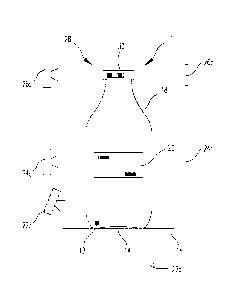
Fig. 2 shows a further embodiment of the present invention. Again, a test
container 10 is
passed through a container inspection system on a conveyor.
In this case, the container inspection system has three detection devices,
namely a
bottom inspection 22, a side wall inspection 24 and a mouth inspection 26.
Each of these
detection devices 22, 24, 26 is formed by a radiation source 22a, 24a, 26a and
an associated
detection device 22b, 24b, 26b.
The test container 10 again has an error 12 in the bottom area 14, which must
be detected
by the bottom inspection 22 a,b. In the other two test areas, i.e. on the side
wall 18 and in the
mouth region 28, a marking 20,30 is provided in each case, which identifies
the container as
test container 10 and contains the information about the type and location of
the test feature
12.
The mode of operation of this embodiment is essentially identical to the mode
of operation
described in Fig. 1. However, the fact that in this case the marking 20, 30 is
provided in two
areas increases the operational safety of this embodiment even more. In the
unlikely event that
neither the bottom inspection 22 a,b detects the test feature 12 nor the side
wall inspection 24
a,b detects the test container marking 20 on the side wall 18, the test
container marking 30 is
also provided in the mouth region 28 of the test container 10 as an additional
redundant safety
measure, so that a further detection device 26 a,b is provided here to
identify the test container
as such.
Inadvertent failure to reject a test container 10 can be almost completely
ruled out here,
as it is extremely unlikely that all three detection devices 22 a,b, 24 a,b
and 26 a,b will
malfunction simultaneously.
With this embodiment, the protocol can be kept in such a way that not only is
it recorded
whether the test containers 10 have all been correctly detected, but it can
also be recorded
whether all detection devices 22 a,b, 24 a,b and 26 a,b have delivered
consistent results.
Depending on the performance of the individual detection devices 22 a,b, 24
a,b and 26 a,b,
the inspection system can then be checked immediately or at a possibly more
suitable later
time.
Date Regue/Date Received 2022-02-15