Note: Descriptions are shown in the official language in which they were submitted.
- 1 -
Dispenser, retrofit kit for a dispenser, a method for provision of portions of
a tissue web and a
method for upgrading a dispenser
The invention relates to a dispenser for provision of portions of a tissue
web, a retrofit kit for a
dispenser, a method for provision of portions of a tissue web and a method for
upgrading a
dispenser.
Dispensers and methods for provision of portions of a tissue web are known,
for example, from
EP119187261, EP2810259B1, EP028355461, EP048331461. Existing dispensers and
methods,
however, in practice still have room for improvement regarding reliability and
trouble-free
operation.
Therefore, it is an object of the present invention to provide an improved
dispenser for provision of
portions of a tissue web, an improved retrofit kit for a dispenser, an
improved method for provision
of portions of a tissue web and an improved method for upgrading a dispenser.
In particular, it is
an object of the present invention to provide a dispenser for provision of
portions of a tissue web, a
retrofit kit for a dispenser, a method for provision of portions of a tissue
web and a method for
upgrading a dispenser, which are highly reliable and/or reduce troubles and/or
faults during
operation.
According to a first aspect, it is provided a dispenser for provision of
portions of a tissue web,
comprising a first transport arrangement for unused tissue and a second
transport arrangement for
used tissue, a housing with a dispensing opening through which a tissue
portion located between
the first transport arrangement and the second transport arrangement
protrudes, a detection
arrangement comprising at least one sensor unit, preferably comprising a first
sensor and a
second sensor, for detecting a user change, a control unit adapted to activate
the second transport
arrangement when a user change is detected.
The dispenser is preferably suitable for washrooms and other hygienic
environments. The
dispenser comprises a housing. The housing preferably comprises a back part
and an openable
housing cover with a front face. The housing further has a dispensing opening.
The tissue to be dispensed from the dispenser can be a multiuse tissue, such
as a cloth towel or
microfiber towel, or a single-use tissue, such as a paper tissue or a
reinforced paper tissue, for
example. The tissue is preferably provided as a continuous web, for example
coiled up to a tissue
roll or folded in a stack, e.g. concertina-like.
Date Recue/Date Received 2020-11-25
- 2 -
Portions of the tissue web, which preferably means a certain length of tissue
to be used by a user,
often for drying hands, are provided by the dispenser. The portion to be used
by a user protrudes
through dispensing opening in the housing, such that the user can access the
portion. Preferably,
the portion is provided as a, preferably hanging, loop of tissue web. For
example, the dispensing
opening may have a front and a back slot, preferably separated by an
intermediate part of the
housing. For example, a part of the tissue portion facing the user may
protrude through the front
slot and a part of the tissue portion facing the wall (in a wall-mounted
dispenser) may protrude
from the back slot.
Preferably, the dispensed and used portions of tissue can be retrieved and
coiled, for example
within the dispenser. Usually, the used multiuse tissue is removed by service
personnel, washed
and recycled, and then provided for a further use cycle. Once a tissue roll is
empty, usually a new
tissue roll, which also can be a recycled tissue roll, is inserted into the
dispenser and received
there by some form of holding arrangement.
The dispenser comprises a first transport arrangement for unused tissue and a
second transport
arrangement for used tissue. The tissue portion protruding through the
dispensing opening is
located between the first transport arrangement and the second transport
arrangement. Preferably,
the first transport arrangement is adapted to provide unused tissue in the
form of a continuous web
by uncoiling it from a roll of unused tissue. Further preferably, the second
transport arrangement is
adapted to retrieve used tissue, preferably by coiling it to a used tissue
roll.
Dispensers with a first and second transport arrangement, in particular
dispensers with a multiuse
tissue web that is retrieved after use, can also be referred to as retracting
dispensers.
The dispenser further comprises a control unit adapted to activate the second
transport
arrangement. Preferably, the control unit is further adapted to activate the
first transport
arrangement and/or to deactivate the first transport arrangement and/or to
deactivate the second
transport arrangement. Further preferably, the control unit can be adapted to
control further
elements of the dispenser.
The dispenser further comprises a detection arrangement. The detection
arrangement has at least
one sensor unit for detecting a user change. In particular, the detection of a
user change is meant
as a detection of a change in the person using the dispenser. For example, the
detection of a user
change can comprise the detection of a change in the position of a person
using the dispenser in
combination with the detection of the end of a use and/or the beginning of a
new use. Preferably,
the detection of a user change can comprise the detection of the departure of
a user, possibly
including the departure speed of a user, and/or the approach of a user,
possibly including an
approach speed.
Date Recue/Date Received 2020-11-25
- 3 -
Preferably, the sensor unit comprises a first sensor. This first sensor can be
the only sensor of the
sensor unit. Further preferably, the sensor unit comprises a first sensor and
a second sensor. In
particular, the first sensor and the second sensor can be employed for
together detecting a user
change, for example having a first sensor detecting a change in the position
of the person using
the sensor and the second sensor detecting the end and/or beginning of a use.
The sensor unit can comprise one or more sensors, e.g. a first sensor and
possibly further sensors
like a second, third, fourth or further sensors. The sensor(s) of the sensor
unit can be separate
sensors. The sensor(s) of the sensor unit also can be integral and/or an
integrated sensor and/or
integrated into one single sensor element. For example, the sensor unit and/or
one of its sensor(s)
can be adapted to generate one or more sensor signals, e.g. based on one or
more detection
principles and/or one or more detection fields, wherein the detection
principles may be the same or
different ones and/or the detection fields may be the same or different ones.
Preferably, the detection arrangement and/or the sensor unit, in particular
the first sensor and/or a
second sensor, is connected to further components of the dispenser, for
example the control unit,
in a wired or wireless way. The sensor(s) of the detection arrangement and/or
the sensor unit can
be connected to each other and/or to further components of the dispenser, for
example the control
unit, in a wired or wireless way.
The control unit of the dispenser is adapted to activate the second transport
arrangement upon
detection of a user change by the detection arrangement. In particular, it is
preferred that such an
activation of the second transport arrangement results in the at least partial
retraction of the tissue
portion protruding through the dispensing opening back into the housing of the
dispenser, in
particular by coiling the used tissue on a used tissue roll by the second
transport arrangement.
The solution as described herein is based on the finding that existing
dispensers and methods for
providing portions of tissue have drawbacks in particular in high-frequency
operating situations.
High-frequency operating situations typically are situations where a high
number of users intends
to use the dispenser in quick succession. Existing dispensers, in particular
retracting dispensers,
may not be adapted for such a high-frequency use. In particular, the
retrieving of used tissue by a
second transport arrangement may be too slow or too delayed for such a quick
succession of
uses. Typically, in retracting dispensers, the retrieval of used tissue by the
second transport
mechanism takes place after a certain time after unused tissue has been
provided to the
dispensing opening. The reason for this delay of the retrieval of the used
tissue portion is to give a
user sufficient time to use the portion of tissue protruding through the
dispensing opening. The use
of this tissue portion typically takes place by a user grabbing the tissue
portion and moving it over
his hands for drying hands. A retrieval of used tissue by the second transport
arrangement directly
after provision of the tissue portion by the first transport arrangement would
result in the user not
Date Recue/Date Received 2020-11-25
- 4 -
having a large enough portion protruding from the dispensing opening for
actually accessing this
tissue portion and using it for drying the hands.
While this operating principle has a number of advantages and make sense in a
number of regular
or low-frequency operating situations, it does have drawbacks in high-
frequency operating
situations. When a quick succession of users activates the provision of tissue
portions from a
reservoir of unused tissue, in particular via the first transport arrangement,
to protrude through the
dispensing opening in a higher frequency than the used tissue is retrieved by
the second transport
arrangement, the tissue portion protruding from the dispensing opening will
get larger and larger
over time. It often happens that the tissue portion protruding from the
dispensing opening in such a
situation gets too large and thus too heavy to be retrieved by the second
transport arrangement.
This can lead to so-called "floor loops", in which the tissue portion
protruding from the dispensing
opening becomes so large that it reaches the floor of a washroom.
The solution as described herein is based on the finding that such drawbacks
can be avoided
when the second transport arrangement is activated as soon as the person using
the dispenser
.. changes. Thus, the solution as described herein provides for a detection
arrangement for detecting
a user change and a control unit for activating the second transport
arrangement upon such
detection. When in a high-frequency operating situation the user takes shorter
time to dry his or
her hands than the usual delay for retrieving the used tissue, the solution
described herein detects
such a user change and activates the second transport arrangement. This has
the advantage that
as soon as a user change occurs, the retrieval of the used portion can be
initiated. In this way, it
can be avoided that two or even more times an unused tissue portion is
provided through the
dispensing opening before a used tissue portion is retrieved. Increasingly
large loops, and even
floor loops, can be avoided in this way.
The control unit preferably is connected to various components of the
dispenser using a wired or
wireless connection in order to transfer signals, e.g. sensor signals,
activation signals, deactivation
signals, control signals and the like, and to generate and/or process and/or
receive and/or
transmits such signals. Further preferably, the control unit may, using either
a wireless or wired
connection, also be connected to external components, for example a washroom
information
system, an external communication unit and/or a backend unit.
The control unit preferably is adapted to communicate with an external
communication unit and/or
with a backend unit, preferably in a bidirectional way and/or in a wireless
way. Preferably,
information can be transferred from the control unit to the external
communication unit and/or to
the backend unit. Further preferably, information, such as software updates
and/or settings and/or
update of (operational) parameters, can be received from the external
communication unit and/or
from the backend unit by the control unit. It is further preferred that the
external communication
Date Recue/Date Received 2020-11-25
- 5 -
unit and/or the backend unit is adapted and arranged to communicate,
preferably in a bidirectional
way, with a plurality of arrangements and/or a plurality of dispensers. For
example, the wireless
communication can be realized by a Bluetooth connection. Further preferably,
the external
communication unit and/or the control unit is adapted and arranged to
communicate, preferably in
a wireless way, such as Bluetooth, to a backend unit, in particular in order
to exchange client
specific and/or process related information. Further preferably, the control
unit and/or the external
communication unit and/or the backend unit is adapted and arranged to
communicate with one or
more mobile devices like tablets and/or smart phones, preferably in a
bidirectional way and/or in a
wireless way.
Preferably, the dispenser can be part of a system further comprising an
external communication
unit and/or a backend unit and/or one or more mobile devices.
In a preferred embodiment, the control unit is adapted to activate the first
transport arrangement
when a user change is detected. In this embodiment, the event of a user change
can also trigger
the activation of the first transport arrangement, which preferably results in
dispensing a further
unused portion of tissue web through the dispensing opening. In this way, the
new user does not
need to activate, for example manually or via an automatic, e.g. non-touch,
activation mechanism,
the provision of a new portion of tissue web. Rather, by activating the first
transport arrangement
upon detection of a user change, the new user will be provided with an unused
tissue portion
without the need for further action from his or her side.
Preferably, the detection arrangement, in particular the sensor unit,
comprises a third and/or fourth
and/or further sensor(s) for detecting a user change. Preferably, also the
third and/or fourth and/or
further sensor(s) for detecting a user change can have the features,
characteristics and
advantages as described herein for the first and/or second sensor. Further, it
is preferred that a
combination of the sensors of the detection arrangement and/or the sensor unit
or all sensors of
the detection arrangement and/or the sensor unit contribute to the detection
of a user change. For
example, some or all of the sensors of the detection arrangement and/or the
sensor unit, in
particular their individual sensor signals, may be used and/or assessed as a
whole, and/or
interdependently, in order to detect a user change. In particular, the
detection arrangement and/or
the sensor unit and/or the control unit can be adapted to detect a user change
and/or to activate
the second transport arrangement upon detection of a user change depending on
a combination of
signals from a plurality or all of the sensors of the detection arrangement
and/or the sensor unit.
Preferably, the first sensor and/or the second sensor and/or the third sensor
and/or the fourth
sensor and/or the further sensor(s) can have the same or different detection
principles. For
example, the sensors can be of the same or different types. In this way, the
accuracy and reliability
of the detection of a user change can be improved.
Date Recue/Date Received 2020-11-25
- 6 -
Further preferably, the first sensor and/or the second sensor and/or the third
sensor and/or the
fourth sensor and/or the further sensor(s) can have the same or different
detection fields. For
example, the detection fields of the sensor(s) can vary, e.g. regarding their
size and/or range
and/or direction and/or sensibility. Again, in this way, the accuracy and
reliability of the detection of
.. a user change can be improved. Further preferably, a detection field can be
directed upwards,
downwards, sideward, forward, rearward or any combination thereof.
Preferably, the detection arrangement and/or the sensor unit and/or at least
one of or all of the
sensor(s) can be arranged such that the detection field can be adjusted. For
example, the
detection arrangement and/or the sensor unit and/or at least one of or all of
the sensor(s) can be
.. pivotable, e.g. about a horizontal and/or about a vertical pivot axis. This
has the advantage that the
detection arrangement can be adjusted, for example for different operating
situations.
In particular, it can be preferred that at least one of the sensors and/or the
sensor unit has a
detection field in the direction of a user. A detection field in the direction
of a user can be directed
towards the torso of a user and/or towards the (likely) position of the user's
hands during the
drying process. For example, a detection field in the direction of a user can
be substantially
horizontal and/or angled downwards and/or angled upwards.
Further, it can be preferred that at least one of the sensors and/or the
sensor unit has a detection
field in the direction of the tissue web, in particular in the direction of
the protruding portion of the
tissue web, in particular its part facing the user.
In a preferred embodiment at least one of the sensors and/or the sensor unit
is positioned on a
front face of the dispenser, in particular on a lower part thereof.
Preferably, at least one of the
sensors and/or the sensor unit can be positioned adjacent or near the
dispensing opening. Further
preferably, at least one of the sensors and/or the sensor unit is positioned
on an intermediate part
of the dispenser housing. Further preferably, at least one of the sensors
and/or the sensor unit is
positioned inside the housing and/or arranged at the housing, in particular on
its outside or on its
inside, and/or separate from the dispenser, e.g. next to the dispenser.
In particular, different combinations of the details of individual sensors can
be preferred to create a
detection arrangement and/or a sensor unit having a high speed and/or high
accuracy and/or high
reliability and/or short reaction time in detecting a user change while at the
same time having a low
energy consumption.
For example, the first sensor and/or the second sensor and/or the third sensor
and/or the fourth
sensor and/or the further sensor(s) can be chosen from the following group of
sensors, comprising
or consisting of: acceleration sensor, motion sensor, thermal sensor, infrared
sensor, radiation
Date Recue/Date Received 2020-11-25
- 7 -
sensor, in particular electromagnetic radiation sensor, optic sensor, time-of-
flight sensor,
capacitive sensor, image sensor, reflective sensor, pyroelectric (passive)
infrared sensor,
thermopile sensor.
In particular, sensors are preferred having sharp signals and/or low noise
and/or fast response
time and/or low energy consumption.
For example, a sensor unit can be preferred, having an infrared sensor and an
acceleration
sensor. As described above, these two sensors of the sensor unit can be
separate sensors or
implemented as an integrated sensor, providing for both infrared detection and
acceleration
detection, for example. An acceleration sensor with a low energy consumption
can be used, for
example, for continuously detecting whether a user pulls the tissue or not. If
it is detected that a
user pulls a tissue, the infrared sensor (and possibly also a control unit)
preferably is switched from
an inactive, energy-saving mode, to an active mode. The infrared sensor then
preferably detects
whether a user approaches and/or leaves the dispenser. The infrared sensor and
the control unit
can be arranged on a single circuit board, for example.
In general, the sensor(s) and/or detection principles and/or detection fields
used herein are
preferably adapted to detect a user change independent from and/or despite
possibly interfering
factors such as light, e.g. sunlight, artificial light, UV light, and/or
radiation, in particular
electromagnetic radiation, and/or electromagnetic fields and/or reflective
and/or colored surfaces
and/or heat sources like radiators.
Further, it is preferred that the sensitivity and/or the detection field of
the detection arrangement
and/or the sensor/ and/or at least one of or all of the sensor(s) can be
adjusted. For example, the
detection field of a sensor, e.g. of an infrared sensor, can be enlarged or
reduced. This can be
realized, for example, by positioning a sensor, e.g. an infrared sensor,
behind a plate with a hole,
acting as an aperture. By varying the distance between the sensor and the
plate with a hole, the
sensitivity and/or the detection field can be varied.
Further preferably, at least two of the first sensor and/or the second sensor
and/or the third sensor
and/or the fourth sensor or the further sensor(s), preferably three or more or
all of the sensors, are
arranged on a single circuit board, in particular a single printed circuit
board.
Preferably, also the control unit can be arranged on the same single circuit
board, in particular on
the same single printed circuit board. Alternatively, the control unit can be
provided on a separate
(printed) circuit board. The provision of several components on a single
circuit board has the
advantage of a compact and solution which is easy to manufacture and/or to
install and/or to
exchange and/or to service. A single circuit board also has a cost advantage
and can be less
Date Recue/Date Received 2020-11-25
- 8 -
susceptible to interference than a cable connection, since unshielded cables
may act as antennas
and may emit interference signals.
In a further preferred embodiment, the second transport arrangement comprises
a blocking
element, wherein the activation of the second transport arrangement via
control unit comprises the
release of the blocking element. The blocking element of the second transport
arrangement
preferably is adapted to block the activation of the second transport
arrangement, preferably for a
certain time. In particular, it is preferred that the blocking element is
adapted to block the second
transport arrangement for a certain period of time after the activation of the
first transport
arrangement. Further preferably, the blocking element is adapted to be
released after a certain
period of time. Further preferably, the second transport arrangement is
adapted to automatically,
for example via a biasing mechanism, such as a spring or an electrically
driven mechanism, to
retrieve the used portion of tissue web once the blocking element is released.
When such a blocking element is present, it is particularly preferred that the
activation of the
second transport arrangement via the control unit comprises the release of the
blocking element.
In particular, in case the second transport arrangement is adapted to retrieve
the used portion of
tissue web once the blocking element is released, the activation of the second
transport
arrangement may consist simply in the release of the blocking element. Further
preferably, the
blocking element can be coupled with the activation of the first transport
arrangement such that the
second transport arrangement will automatically be blocked once the first
transport arrangement
has been activated.
In a preferred embodiment, the blocking element is a time controlled,
preferably mechanical,
blocking element. A time controlled blocking element preferably is released
after a predetermined
amount of time. The blocking element can be a mechanical and/or an electric
blocking element
and/or a blocking element based on a different blocking principle.
In a further preferred embodiment, the second transport arrangement comprises
a release element
adapted to release the blocking element.
In particular, the release element is adapted to release the blocking element
before the
predetermined time of a time controlled blocking element. The activation of
the second transport
arrangement, for example, can comprise the activation of the release element,
which then in turn
.. releases the blocking element and thus enables the automatic retrieval of
the used portion of
tissue web by the second transport arrangement.
For example, the release element comprises a valve, in particular an electric
valve and/or a
solenoid valve, and/or a drive, in particular an electric drive.
Date Recue/Date Received 2020-11-25
- 9 -
For example, the release element can comprise an electrically driven solenoid
valve which
interacts with a, for example, pneumatic blocking element in order to release
it. Preferably, the
release element as a low energy consumption and/or is adapted to be battery-
supplied.
The first transport arrangement can comprise a manual transport mechanism
and/or an automatic
.. transport mechanism, in particular a driven transport mechanism, preferably
electrically driven, e.g.
via a battery supply and/or other energy supply. A manual transport mechanism
for the first
transport arrangement preferably is operated by action of a user, only, e.g.
by a user pulling the
tissue, which preferably leads to a corresponding provision of tissue, e.g. by
decoiling and possibly
guiding the tissue via rolls to the dispensing opening. Preferably, a manual
transport mechanism
does not need any energy supply, e.g. in the form of batteries or a power
line.
The second transport arrangement can comprise a manual transport mechanism
and/or an
automatic transport mechanism, in particular a driven transport mechanism,
preferably electrically
driven, e.g. via a battery supply and/or other energy supply. A manual
transport mechanism for the
second transport arrangement preferably is independent from, in particular
electric, energy supply,
e.g. in the form of batteries or a power line. Preferably, the manual
transport mechanism for the
second transport arrangement operates by tensioning and releasing a biasing
element, such as a
spring, and/or via a, preferably mechanical, coupling with the first transport
mechanism.
For example, the dispenser can be a so-called "non-touch" dispenser where the
activation of the
first transport arrangement for dispensing a portion of unused tissue is
realized without having the
.. user making contact with the dispenser of the tissue. For example, a user's
presence in front of the
dispenser can be detected and the first transport arrangement can be activated
thereupon. The
detection of a user's presence can be detected, for example, via the detection
arrangement
described herein and/or via a separate detection unit, which may be
specifically adapted for
detecting whether a user holds his or her hand in front of a detection area of
the dispenser, for
example.
In a further preferred embodiment the detection arrangement is in an energy-
saving sleeping mode
by default and preferably is adapted to raise to an active mode upon
activation of the first transport
arrangement. This embodiment is particularly preferred to save energy
consumption. For example,
the control unit can be adapted to raise the detection arrangement from the
energy saving sleeping
mode to an active mode upon activation of the first transport arrangement.
Alternatively or
additionally, a switch can be provided, for example a reed switch. Preferably,
such a switch is
switched upon activation of the first transport arrangement. The switching of
the switch preferably
results in raising the detection arrangement from energy savings sleeping mode
to an active mode.
For example, a reed switch can be positioned in the vicinity of the blocking
element. A magnet can
be positioned on the blocking element such that when the blocking element
reaches its blocking
Date Recue/Date Received 2020-11-25
- 10 -
position (in particular, when or after the first transport arrangement has
been activated), the
magnet on the blocking element switches the reed switch and thus initiates the
raising of the
detection arrangement to the active mode.
According to a further preferred embodiment the control unit is adapted to
activate the second
transport arrangement when a repeated activation of the first transport
arrangement by a single
user is detected. In practice, situations can arise where a user wants to use
more than one portion
of tissue web and thus repeatedly activates the first transport arrangement.
In such a situation, it is
preferred that increasingly large loops, in particular "floor loops", are
avoided. Thus, it is
advantageous to detect the repeated activation of the first transport
arrangement by the same
user, i.e. a repeated activation of the first transport arrangement without
detecting a user change,
and to activate the second transport arrangement, in particular for retrieval
of the used tissue
portion, in such a situation. In addition, maintenance and service calls and
costs can be reduced,
and the availability of the dispenser for the operator can be increased.
Increasingly large loops are heavy and harder to retrieve by the second
transport arrangement and
thus put additional wear on the second transport arrangement. By providing
solutions for avoiding
increasingly large loops, the lifespan and reliability of the second transport
arrangement can be
increased.
In a further preferred embodiment the control unit is adapted to activate the
second transport
arrangement when a departure speed of a user is detected that is above a
threshold value, in
particular in case such a departure speed is detected after a certain amount
of time has elapsed
after a manual activation of the first transport arrangement by a user.
When the first transport arrangement is a manual activation mechanism, such as
in dispensers
where the user actively pulls the tissue web, movements may occur right after
the pulling of the
tissue by the user that resemble a high departure speed. Therefore, the
activation of the second
transport arrangement in case of a high departure speed is particularly
preferred only after a
certain amount of time after a manual activation of the first transport
arrangement.
Individual or all embodiments relating to the dispenser, in particular the
detection arrangement
and/or the control unit, can be combined and have particular advantages, also
in the specific
combinations.
According to a further aspect, it is provided a retrofit kit for a dispenser
according to at least one of
the preceding claims, the retrofit kit comprising a detection arrangement
comprising at least one
sensor unit, preferably comprising a first sensor and a second sensor, for
detecting a user change
Date Recue/Date Received 2020-11-25
- 11 -
a control unit adapted to activate a second transport arrangement of the
dispenser when a user
change is detected.
It is particularly preferred that the retrofit kit comprises a release element
adapted to release a
blocking element of the second transport arrangement of the dispenser.
According to a further aspect, it is provided a method for provision of
portions of a tissue web, the
method comprising transporting unused tissue and transporting used tissue such
that a tissue
portion located between a first transport arrangement and a second transport
arrangement
protrudes through a dispensing opening in a housing of a dispenser, detecting
a user change, in
particular with a detection arrangement comprising at least one sensor unit,
preferably comprising
a first sensor and a second sensor; activating the second transport
arrangement when a user
change is detected.
According to a further aspect, it is provided a method for upgrading a
dispenser for provision of
portions of a tissue web, the method comprising installing a retrofit kit as
described herein in a
dispenser for provision of portions of a tissue web, the dispenser comprising
a first transport
arrangement for unused tissue and a second transport arrangement for used
tissue and a housing
with a dispensing opening through which a tissue portion located between the
first transport
arrangement and the second transport arrangement protrudes.
As to the advantages, preferred embodiments and details of these further
aspects and their
preferred embodiments, reference is made to the corresponding advantages,
preferred
embodiments and details described above.
Preferred embodiments shall now be described with reference to the attached
drawings, in which
Fig. 1: shows an example of a wall-mounted dispenser with three users in a
high-frequency
operating situation;
Fig. 2: shows a side view of an example of a dispenser with first and
second transport
arrangements;
Fig. 3: shows examples of two dispensers with two different detection
principles;
Fig. 4: shows examples of three sensors with three different detection
principles;
Fig. 5: shows an example of a dispenser in different stages of use and a
possible detection
principle;
Date Recue/Date Received 2020-11-25
- 12 -
Fig. 6: shows a detail of a section of an example of a dispenser with a
second transport
arrangement and a front slot of a dispensing opening;
Fig. 7: shows side views of examples of three dispensers with different
positions of sensors
having detection fields in different directions;
Fig. 8: shows an example of a dispenser over a washbasin;
Fig. 9: shows an example of a dispenser with a sensor having a detection
field in the
direction of a user;
Fig. 10a: shows a further example of a dispenser with a sensor having a
detection field in the
direction of a user;
Fig. 10b: shows an example of a dispenser with a sensor having a detection
field in the
direction of a user where three users queue in line;
Fig 11: shows an example of a dispenser with a sensor having a detection
field in the
direction of the hands of a user;
Fig 12: shows a further example of a dispenser with a sensor having a
detection field in the
direction of the hands of a user;
Fig 13: shows an example of a dispenser over a washbasin having a
detection field in the
direction of the hands of a user;
Fig 14: shows an example of a blocking element of a second transport
arrangement and a
release element;
Fig 15: shows an example of a first schematic set up of a detection
arrangement and a
control unit;
Fig 16: shows an example of a second schematic set up of a detection
arrangement and a
control unit;
Fig 17: shows an example of a schematic basic set up of sensors on a
printed circuit board;
Fig 18: shows an example of a schematic flow diagram of an activation of
the second
transport arrangement;
Date Recue/Date Received 2020-11-25
- 13 -
Fig 19: shows two examples of a sensor output evaluation;
Fig 20: shows an example of an evaluation of sensor data of a first
sensor;
Fig 21: shows an example of an evaluation of sensor data of a second
sensor;
Fig 22: shows an example of a schematic flow diagram of a method for
provision of portions
of a tissue roll; and
Fig 23: shows an example of a schematic flow diagram of a method for
upgrading a
dispenser for provision of portions of a tissue web.
In the figures, elements with the same or comparable functions are indicated
with the same
reference numerals.
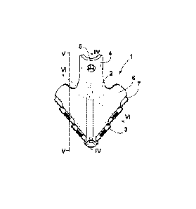
Figure 1 shows an example of a wall-mounted dispenser 1 with three users U in
a high-frequency
operating situation. Figure 2 shows a dispenser 1 in a side view.
The dispenser 1 for provision of portions of a tissue web 30 has a first
transport arrangement 41
and a second transport arrangement 42. In the figures, only schematic parts of
the first and second
transport arrangement 41, 42 are shown. Further, the dispenser 1 has a housing
10 with a back
part 13, in particular for wall mounting the dispenser 1, and an openable
housing cover 11 with a
front face 12. The dispenser 1 further has a dispensing opening 20 comprising
a front slot 21 and a
back slot 22. The front slot 21 and the back slot 22 are separated by an
intermediate part 14 of the
housing 10.
A tissue portion 33 located between the first transport arrangement 41 and the
second transport
arrangement 42 protrudes through the dispensing opening 20. The tissue portion
33 protruding
through the dispensing opening 20 has the form of a loop, as can be seen in
Figure 1, for example.
A part 33a of the tissue portion 33 faces the user U and a part 33b of the
tissue portion 33 faces
the wall or away from the user. Typically, the part 33a of the tissue portion
33 facing the user is
unused. The part 33b of the tissue portion 33 facing the wall may be used.
Preferably, unused tissue 31 is provided in a coiled form as a roll and
dispensed through the front
slot 21 of the dispensing opening 20 by the first transport arrangement 41.
Once a user U has
dried his or her hands, the part 33b of the tissue portion 33 facing the wall
is retracted through the
back slot 22 of the dispensing opening 20 via the second transport arrangement
42 and coiled up
to a roll of used tissue 32.
Date Recue/Date Received 2020-11-25
- 14 -
In the next dispensing cycle, when the first transport arrangement 41 is
activated and provides
tissue web 30 through the front slot 21 of the dispensing opening 20, the
former part 33a of the
tissue portion facing the user U, which has just been used, becomes the part
33b of the tissue
portion facing the wall. In this way, the part 33a of the tissue portion 33
facing the user U is usually
freshly dispensed from the unused tissue 31 through the front slot 21 of the
dispensing opening 20
via the first transport arrangement 41. Once this part 33a of the tissue
portion 33 has been used
and the part 33b of the tissue portion 33b facing the wall has been retracted
through the back slot
22 of the dispensing opening 20 by the second transport arrangement 42, the
former user facing
part 33a of the tissue portion 33 becomes the new wall facing part of the
tissue portion 33b.
The dispenser 1 further comprises a detection arrangement 100 with a sensor
unit 120 comprising
a first sensor 101 and a second sensor 102 for detecting a user change.
Preferably, the detection
arrangement can comprise a third sensor 103 and possibly a fourth sensor and
possibly further
sensor(s). Further, a control unit 50 is provided, which is adapted to
activate the second transport
arrangement 42 when a user change is detected. Further preferably, the control
unit 50 is also
adapted to activate the first transport arrangement 41 when a user change is
detected.
Figures 3, 4, and 5 show dispensers 1 with different detection arrangements
100 having at least a
first and a second sensor 101, 102, for detecting a user change. For example,
the detection
arrangement 100 in the left-hand dispenser 1 in figure 3 is arranged at the
intermediate part 14 of
the housing 10 of the dispenser 1 and adapted to detect movements of the hands
H of a user U
and the resulting movements of the portion 33 of tissue web 30 protruding from
the dispensing
opening 20. On the right-hand side of figure 3, the detection arrangement 100
of the dispenser 1 is
adapted to detect the proximity of a user U or in his or her hand H in front
of the sensor 1.
The left-hand dispenser 1 in figure 4 has a detection arrangement 100
comprising a first sensor
101 in the form of a passive infrared sensor for detecting the proximity of a
user's U and H. In the
middle of figure 4, a dispenser 1 is depicted comprising a second sensor 102
in the form of a
capacitive sensor, which is also adapted to detect the presence of a user's U
hands H. On the
right-hand side of figure 4, a dispenser 1 is depicted with a detection
arrangement 100 having a
third sensor 103 in the form of a TOF sensor adapted for detecting a user's U
presence, as well as
his or her arrival and/or departure to or from the dispenser 1.
Figure 5 shows a dispenser 1 with different forms of the portions 33 of tissue
web 30 protruding
from the dispensing opening 20 during use. On the left-hand side of figure 5
the portion 33
protruding from the dispensing opening 20 of the dispenser 1 is small. In the
second depiction of
the dispenser 1 in figure 5 the first transport arrangement 42 has been
activated by pulling the
tissue and the portion 33 protruding from the dispensing opening 20 has
increased and clearly
shows a user facing part 33a and a wall facing part 33b. In the third
depiction of the dispenser 1 in
Date Recue/Date Received 2020-11-25
- 15 -
figure 5, the loop of the portion 33 of tissue web is hanging freely from the
dispensing opening 20.
The right-hand side depiction of the dispenser 1 in figure 5 shows a situation
similar to the second
depiction of the dispenser 1 in figure 5, whether loop of the portion 33 of
the tissue web is tilted
towards the right-hand side, which means in the direction towards the user U.
In particular, when a
user U uses a dispenser 1, he would draw the loop of the portion 33 of tissue
web, in particular the
part 33a towards him or her, leading to a situation as depicted in the second
and fourth depiction
of the dispenser 1 in figure 5. For the detection of the movement of the
tissue, a sensor can be
deployed, for example, detecting the varying distance between the user facing
part 33a of the
portion 33 protruding from the dispensing opening 20 and the intermediate
portion 14 of the
housing, as indicated in the second and third depiction of the dispenser 1 in
figure 5. Alternatively
or additionally, the detection arrangement 100 may comprise a sensor 104
depicted on the right-
hand side in figure 5, adapted to detect the position of the wall facing part
33b of the tissue portion
33 protruding from the dispensing opening.
The individual sensors and detection principles shown herein are preferably
combined in a
detection arrangement and/or in a sensor unit 120 having at least a first and
a second sensor 101,
102, which together produce a combination of sensor signals based on which a
change user can
be detected.
Figure 6 shows a detailed of a section of an example of the dispenser 1 with a
roll 41a of a first
transport arrangement 41 and a front slot 21 of a dispensing opening 20. The
front face 12 of the
housing cover 10 is positioned a first sensor 101 of a detection arrangement
100. In figure 6, two
different positions of the user facing part 33a of the tissue web is shown.
33a' schematically shows
the position when a user pulls the user facing part 33a of the tissue web.
33a" indicates a situation
where the loop of tissue web can hang freely and the front facing part 33a"
hangs downward
through the front such 21 of the dispensing opening 20.
Figure 7 shows three dispenses 1 with different positions of sensors 101
having different detection
fields 110 oriented in different directions. On the left-hand side, the sensor
101 is positioned at a
lower end of the intermediate housing part 14 and has a detection field 110
directed to the lower
end of the user facing part 33a of the portion 33 of tissue web protruding
from the dispensing
opening 20. In the middle of figure 7, the sensor 101 is positioned at an
upper end of the
intermediate housing part 14 and has a detection field 110 directed to the
inner side of the loop of
the tissue portion 33. On the right side of figure 7, the sensor 101 is
located at a lower part of the
front face 12 of the housing 10 and has a detection field 110 directed towards
a likely position of a
user's U hands H during use of the dispenser 1.
Figure 8 shows a dispenser 1 with a sensor having a similar detection field
110 as on the right-
hand side of figure 7 in a situation where a dispenser 1 is wall-mounted over
a washbasin 2.
Date Recue/Date Received 2020-11-25
- 16 -
Figure 9 shows it is one with a detection arrangement having at least one
sensor with a detection
field 110 in a substantially horizontal direction towards a user U.
Figure 10a shows a dispenser 1 having a detection arrangement with at least
one sensor having a
detection field 110 in the direction of a user U. Figure 10b shows a similar
situation as figure 8 but
with a queue of three users U, i.e. a high-frequency situation.
Figure 11 shows a dispenser 1 with a detection arrangement having at least one
sensor with a
detection field 110 directed towards the likely position of the hands H of a
user U during use of the
dispenser 1.
Figure 12 shows a dispenser 1 similar to the dispenser depicted in figure 11
in a top view.
Figure 13 shows a dispenser 1 similar to the dispenser depicted in figure 11.
In figure 13,
additional washroom components are shown, which are common in practice and
often pose
challenges to the correct detection of a user change, in particular a
washbasin 2 with metallic
surface, ceiling mounted elements 3 like heat radiators, light bulbs, or
heaters and underfloor
heating 4.
Figure 14 shows an example of a blocking element 210 of a second transport
arrangement 42 and
a release element 220. The blocking element 210 is in the form of a time
controlled, mechanical
blocking element having a spring 211 and a pneumatic component 212 controlled
by a time
controlled valve 215.
When the first transport arrangement 41 is activated, the blocking element 210
is moved against
the force of spring 211 into its blocking position, where the pneumatic
element 212 is brought
against the wall 213 having a hole 214. The pneumatic element 212 is sucked
there against and
will be released only after a certain amount of time, which is defined by the
time controlled valve
215. For example, the certain amount of time, after which the pneumatic
element 212 will be
released, can be changed by adjusting or exchanging the time controlled valve
215.
On the other side of the wall 213, the opening 214 it is closed by a closure
element 222 connected
to a release valve 221 in the form of a solenoid valve. This release element
220 is adapted to
release the blocking element 210 by moving the closure element 222 away from
the hole 214. In
this way, the pneumatic element 212 relaxes prematurely, i.e. before the
determined time of the
time controlled valve 215 of the blocking element 210 is over.
Once the pneumatic element 212 is released (either after a certain time via
the time controlled
valve 215 or prematurely via the release valve 221), the blocking element 210
moves back into its
Date Recue/Date Received 2020-11-25
- 17 -
unblocked position shown on the left-hand side in figure 14 via the force of
spring 211. The detail
on the right-hand side on figure 14 shows the blocking element 210 in its
blocking position.
Figures 15 and 16 show examples of schematic setups of a detection arrangement
100 and a
control unit 50. In principle, a retrofit kit 300 as described herein can
comprise or consist of such a
.. detection arrangement and a control unit. For example, in figure 15, a
first printed circuit board 51
as well as a second and third printed circuit board 52 and 53 are provided.
The first printed circuit
board 51 is the main board comprising the CPU and the batteries and is
connected via for spring
connectors 54 to the third printed circuit board 53 the which the release
valve 221 of the release
element 220 and a switch, preferably a magnetic switch 230 are connected to
activate the release
element. Further, the first printed circuit board 51 is connected to a second
printed circuit board 52
housing a sensor 101, for example a time of flight sensor, and having a
detection field 110.
Figure 16 shows an example, where a first sensor 101, for example a time of
flight (TOF) sensor
having a detection field 110, a second sensor 102, for example an infrared
sensor having a
detection field 110, and a third sensor 103, for example and acceleration
sensor, are all located on
one single printed circuit board 51 together with the control unit 50. In this
case, on the main
printed circuit board also the CPU and the battery are positioned. H having a
detection field 110.
The release valve 221 of the release element is connected to this single
printed circuit board 51.
Figure 17 shows a further example of a printed circuit board with a first
sensor, for example a time
of flight sensor 101 with a detection field 110, a second sensor 102, for
example in the form of an
infrared sensor with a detection field 110 a third sensor 103 in the form of
an accelerometer.
Figure 18 shows a schematic flow diagram of an example activation of the
second transport
arrangement. On the right-hand side, the steps related to the blocking element
210 are shown, on
the left-hand side the steps related to the detection arrangement 100 are
shown. Step 401 depicts
the start, which can be the activation of the first transport arrangement.
This moves the blocking
elements 210 in the blocking position and thereby switches the switch 230.
This leads to the
raising of the detection arrangement 100 from energy-saving sleeping mode to
an active mode in
step 403. In the following steps, the sensors of the detection arrangement 100
are detecting
whether the user change takes place or not. Firstly, in step 404 it is
detected whether a user is
present in front of the dispenser. In step 408 the value is stored in case a
user is present in front of
the sensor. In step 406 it is determined whether the user moves away from the
sensor. This is
done as long as the user does not move away. As soon as the user does move
away, the release
element is activated in step 407 and the blocking element 210 is released.
Subsequently, in step
408, the detection arrangement goes back into energy-saving sleeping mode.
Date Recue/Date Received 2020-11-25
- 18 -
Further, after step 403 and parallel to step 404, a timer countdown is started
in step 409, wherein
in step 410 a time value can be set for this timer countdown. This timer
countdown preferably
corresponds to the predetermined time of the time controlled locking element
210. Step 411
checks whether the timer has counted down to zero. Once the timer is counted
down to zero, the
detection arrangement 100 is also put into energy-saving sleeping mode again,
possibly without
activating the release element in step 407, in case the timer has counted down
to zero before a
user change has been detected in steps 404,406 and 408.
Figure 19 shows an example of two different sensor outputs over time. For the
reliability and
accuracy of the detection of a user change it is advantageous when the sensor
output gives a
clear indication, of an event to be detected. In the left-hand example of
figure 19, the sensor signal
indicates the use of the dispenser when the sensor output is larger than a
threshold for certain
period of time. On the right-hand side of figure 19, a use is detected when
the sensor output, for
example resembling a proximity of a user, is below a certain threshold for
certain period of time.
Sensors are preferred, which produce a reliable sensor signal allowing to
indicate an event in a
very short amount of time, i.e. having a short response time.
Figures 20 and 21 show examples on how sensor signals can be interpreted for
further
assessment, in particular in order to have the control unit act upon detected
events. In Figure 20,
the line S shows the sensor signal indicating the end of usage, and line I
shows the interpretation
thereof that the user is out of range. Figure 21 shows with S1 a peak in the
sensor signal indicating
that a new tissue portion is released and a second peak S2 that the tissue
portion is swinging. The
vertical portion in dashed line I shows the interpretation of the end of
usage.
Figure 22 and 23, finally, show schematic flow diagrams of the following
methods.
Figure 22 shows a method 1000 for provision of portions of a tissue web, the
method comprising
transporting 1001 unused tissue and transporting used tissue such that a
tissue portion located
between a first transport arrangement and a second transport arrangement
protrudes through a
dispensing opening in a housing of a dispenser, detecting 1002 a user change;
activating 1003 the
second transport arrangement when a user change is detected.
The method 2000 for upgrading a dispenser for provision of portions of a
tissue web, depicted in
Figure 23 comprises installing 2001 a retrofit kit 300 in a dispenser for
provision of portions of a
tissue web, the dispenser comprising a first transport arrangement for unused
tissue and a second
transport arrangement for used tissue and a housing with a dispensing opening
through which a
tissue portion located between the first transport arrangement and the second
transport
arrangement protrudes.
Date Recue/Date Received 2020-11-25
- 19 -
LIST OF REFERENCE SIGNS
1 dispenser
2 washbasin
3 ceiling mounted elements
4 underfloor heating
housing
11 openable housing cover
12 front face
13 back part of housing
10 14 intermediate part of housing
dispensing opening
21 front slot
22 back slot
tissue web
15 31 unused tissue
32 used tissue
33 tissue portion protruding through dispensing opening
33a part of tissue portion facing the user
33b part of tissue portion facing the wall
20 41 first transport arrangement
41a roll of first transport arrangement
42 second transport arrangement
50 control unit
51 first printed circuit board
25 52 second printed circuit board
53 third printed circuit board
54 spring connectors
100 detection arrangement
120 sensor unit
Date Recue/Date Received 2020-11-25
- 20 -
101 first sensor
102 second sensor
103 third sensor
104 fourth sensor
110 detection field
210 blocking element
211 spring
212 pneumatic element
213 wall
214 hole
215 time controlled valve
220 release element
221 release valve
222 closure element
230 switch
300 retrofit kit
401 start
402 switching of switch
403 raising the detection arrangement from the energy saving sleeping
mode to an active
mode
404 detecting presence of user in front of dispenser
405 storing the value for presence of user in front of dispenser
406 detecting whether the user moves away from the sensor
407 activation of release element
408 detection arrangement goes back to energy saving sleeping mode
409 staring timer countdown
410 setting time value
411 checking whether the timer has counted down to zero
1000 method for dispensing provision of portions of a tissue web
Date Recue/Date Received 2020-11-25
- 21 -
1001 transporting unused and used tissue such that a tissue portion
protrudes through a
dispensing opening
1002 detecting a user change
1003 activating the second transport arrangement
2000 method for upgrading a dispenser for provision of portions of a tissue
web
2001 installing a retrofit kit in a dispenser
U user
Date Recue/Date Received 2020-11-25