Note: Descriptions are shown in the official language in which they were submitted.
87193440
1
SYSTEM AND METHOD FOR OPTIMIZING POWER CONSUMPTION IN A HYBRID
ELECTRIC VEHICLE
This is a divisional application of Canadian National Phase Patent Application
No. 2,898,505, filed on
5th March, 2014.
BACKGROUND
Hybrid electric vehicles commonly use both the electric and fossil fuel drive
systems to
minimize fuel consumption. As a result, controlling the hybrid vehicle drive
system often includes
making some determination of how best to expend electrical power along with
(or instead of) burning
fossil fuel in the engine. In some circumstances it may be advantageous to
favor the use of electrical
power to a greater degree where in other circumstances the best fuel economy
may be achieved by
burning more fuel in the engine and using less electrical power in the
electric motor generator.
Determining this balance may be difficult and is often counterintuitive
because numerous factors may be
involved in determining the best fuel economy such as the fuel efficiency of
the engine, the quantity and
maximum transfer rate of electrical energy available, losses incurred in the
transfer of electrical energy
at various power levels, as well as the speed of the vehicle, its weight, and
numerous other related
factors.
SUMMARY
According to an aspect of the present invention, there is provided a method of
controlling a
hybrid system, comprising: calculating one or more target electric motor
output torque levels for an
electric motor generator, and one or more target engine output torque levels
for an engine using a
controller; wherein the one or more target electric motor output torque levels
correspond with the one or
more target engine output torque levels, wherein calculating the one or more
target electric motor output
torque levels includes calculating a Hybrid Efficiency Index (HE!) equal to a
predicted change in fuel
consumption divided by a predicted change in stored electrical energy, and
wherein the engine and the
electric motor generator are responsive to the controller, and wherein the
engine, the electric motor
generator, and the controller are included in the hybrid system; operating the
electric motor generator to
produce an actual electric motor output torque using the controller; and
operating the engine to produce
an actual engine output torque using the controller, wherein the controller
selects the actual electric
Date Regue/Date Received 2022-07-11
87193440
2
motor output torque and the actual engine output torque from the one or more
target electric motor
output torque levels and the corresponding one or more target engine output
torque levels.
According to another aspect of the invention, there is provided an apparatus
for performing the
method described above.
Disclosed is a system and method for optimizing the consumption of power in a
hybrid electric
vehicle drive system. Included are techniques for optimizing electrical energy
and fossil fuel
consumption over the full operational cycle from key on to key off, rather
than optimizing consumption
at only each instantaneous point in time. For example, electrical energy is
spent when it will be most
beneficial over the long-term rather than expending electrical energy at the
optimum power level at any
point in time. The system operates to calculate a Hybrid Efficiency Index
(HEI) which, in one
embodiment, is defined as the change in fuel consumption rate divided by the
rate of change in stored
electrical energy. At any instantaneous point in the propulsion phase of the
hybrid vehicle, the desired
powertrain output, the efficiencies of the components, and the engine fuel
efficiency are well
characterized and known to the hybrid system control logic. Thus the HEI can
be calculated for a range
of electrical energy levels at any given point in time, or repeatedly
throughout the operation of the
vehicle, thus continuously quantifying a ratio of the efficiency gain
available if electrical energy is used
instead of fuel energy for an available electrical power output corresponding
to some or all of the current
user torque request.
In another aspect, the system includes a method for determining when a
particular efficiency
gain (HEI value) represents a best use of electrical power. In one disclosed
embodiment, the system
includes a minimum efficiency level, or target HEI below which the HEI will be
considered insufficient
for operating the electric motor. The target HEI is adjusted throughout the
operation of the vehicle to
optimize when the substitution of electrical energy for fossil fuel is most
advantageous. In one instance,
the target HEI is set low enough to expend all available electrical energy
without wasting an opportunity
to harvest energy through, for example, regenerative braking. Similarly, in
another instance, the
minimum efficiency threshold is set at a level where the energy expended over
the entire trip equals the
regenerative energy captured during the operational cycle, or trip.
In another aspect, the system considers whether the storage capacity of the
electrical energy
storage system has been sufficient to store and deliver the
Date Regue/Date Received 2022-07-11
WO 2014/158848
PCT/US2014/020532
3
recaptured energy to the electric motor generator throughout the trip. For
example,
the system may adaptively observe the energy recaptured throughout the trip
and
determine an average expected ratio of how much of the vehicle's kinetic
energy
can he recovered as electrical energy at any given time during the operation
of the
vehicle. Thus the algorithm can determine if adequate storage capacity is
present.
For example, a determination of inadequate storage capacity results in one
instance
in a gradual lowering of the HEI target thus causing electrical energy to be
used
more frequently.
Similarly, in another aspect of the HEI processing algorithm, a regenerative
braking event occurring when the capacity of the energy storage system is
limited
resulting in a failure to capture some of the available regenerative energy
will also
result in a lowering of the HEI target causing the electrical motor to be used
more
frequently to create extra capacity in the energy storage system thus making
it
more likely the system will recover more energy through regenerative braking.
In another aspect, the minimum efficiency threshold may be adjusted up or
down to assist in keeping the energy storage system near a desired storage
capacity. This aspect of HEI processing may be beneficial where it is
advantageous
to keep the energy storage system at approximately a certain charge capacity,
for
example, to extend its service life.
Further forms, objects, features, aspects, benefits, advantages, and
embodiments of the present invention will become apparent from the detailed
description and drawings provided herewith.
Date Recue/Date Received 2020-11-26
WO 2014/158848
PCT/US2014/020532
4
BRIEF DESCRIPTION OF THE DRAWINGS
FIG. 1 illustrates a diagrammatic view of one example of a hybrid system.
FIG. 2 illustrates a general diagram of an electrical communication system
in the FIG. 1 hybrid system.
FIG. 3 illustrates a flowchart showing one aspect of the control system of
FIG. 1 including stages for calculating the HEI for one or more electric motor
discharge power values.
FIG. 4 illustrates a flowchart showing another aspect of the control system
of FIG. 1 including stages for adjusting the minimum efficiency threshold
after a
regenerative braking event.
FIG. 5 illustrates a flowchart showing another aspect of the control system
of FIG. 1 including stages for adjusting the minimum efficiency threshold in
relation to expected energy recovery.
FIG. 6 illustrates a flowchart showing another aspect of the control system
of FIG. 1 including stages for adjusting the minimum efficiency threshold in
relation to an evaluation threshold.
Date Recue/Date Received 2020-11-26
WO 2014/158848
PCT/US2014/020532
DETAILED DESCRIPTION
For the purpose of promoting an understanding of the principles of the
invention, reference will now be made to the embodiments illustrated in the
5 drawings, and specific language will be used to describe the same. It
will
nevertheless be understood that no limitation of the scope of the invention is
thereby intended. Any alterations and further modifications in the described
embodiments and any further applications of the principles of the invention as
described herein are contemplated as would normally occur to one skilled in
the art
to which the invention relates. One embodiment of the invention is shown in
great
detail, although it will be apparent to those skilled in the relevant art that
some
features not relevant to the present invention may not be shown for the sake
of
clarity.
The reference numerals in the following description have been organized to
aid the reader in quickly identifying the drawings where various components
are
first shown. In particular, the drawing in which an element first appears is
typically indicated by the left-most digit(s) in the corresponding reference
number.
For example, an element identified by a "100" series reference numeral will
first
appear in FIG. 1, an element identified by a "200" series reference numeral
will
first appear in FIG. 2, and so on. With reference to the Specification,
Abstract, and
Claims sections herein, it should be noted that the singular forms "a", "an",
"the",
and the like include plural referents unless expressly discussed otherwise. As
an
illustration, references to "a device" or "the device" include one or more of
such
devices and equivalents thereof.
FIG. 1 shows a diagrammatic view of a hybrid system 100 according to one
embodiment. The hybrid system 100 illustrated in FIG. 1 is adapted for use in
commercial-grade trucks as well as other types of vehicles or transportation
systems, but it is envisioned that various aspects of the hybrid system 100
can be
incorporated into other environments. As shown, the hybrid system 100 includes
an engine 102, a hybrid module 104, an automatic transmission 106, and a drive
train 108 for transferring power from the transmission 106 to wheels 110. The
hybrid module 104 incorporates an electric motor generator or electrical
machine,
Date Recue/Date Received 2020-11-26
WO 2014/158848
PCT/US2014/020532
6
commonly referred to as an eMachine 112, and a clutch 114 that operatively
connects and disconnects the engine 102 from the eMachine 112 and the
transmission 106.
The hybrid system 100 incorporates a number of control systems for
controlling the operations of the various components. For example, the engine
102
has an engine control module 146 that controls various operational
characteristics
of the engine 102 such as fuel injection and the like. A transmission/hybrid
control
module (TCM/HCM or "the controller") 148 substitutes for a traditional
transmission control module and is designed to control both the operation of
the
transmission 106 as well as the hybrid module 104. The transmission/hybrid
control module 148 and the engine control module 146 along with the inverter
132,
and energy storage system 134 communicate along a communication link as is
depicted in FIG. 1.
In terms of general functionality, the transmission/hybrid control module
148 receives power limits, capacity, available current, voltage, temperature,
state
of charge, status, and fan speed information from the energy storage system
134
and the various energy storage modules 136 within. In the illustrated example,
energy storage system 134 includes three energy storage modules 136 connected
together, for example connected together in parallel, to supply high voltage
power
to the invert 132. The transmission/hybrid control module 148 in turn sends
commands for connecting the various energy storage modules 136 so as to supply
voltage to and from the inverter 132. From the inverter 132, the
transmission/hybrid control module 148 receives a number of inputs such as the
motor/generator torque that is available, the torque limits, the inverter's
voltage
current and actual torque speed. From the inverter 132, it also receives a
high
voltage bus power and consumption information. The transmission/hybrid control
module 148 also monitors the input voltage and current as well as the output
voltage and current. The transmission/hybrid control module 148 also
communicates with and receives information from the engine control module 146
and in response controls the torque and speed of the engine 102 via the engine
control module 146.
Date Recue/Date Received 2020-11-26
87193440
7
In a typical embodiment, the transmission/hybrid control module 148 and engine
control
module 146 each comprise a computer having a processor, memory, and
input/output connections.
Additionally, the inverter 132, energy storage system 134, DC-DC converter
system 140, and
other vehicle subsystems may also contain computers having similar processors,
memory, and
input/output connections.
FIG. 2 shows a diagram of one example of a communication system 200 that can
be used
in the hybrid system 100. While one example is shown, it should be recognized
that the
communication system 200 in other embodiments can be configured differently
than is shown.
The communication system 200 is configured to minimally impact the control and
electrical
systems of the vehicle. To facilitate retrofitting to existing vehicle
designs, the communication
system 200 includes a hybrid data link 202 through which most of the various
components of the
hybrid system 100 communicate. In particular, the hybrid data link 202
facilitates communication
between the transmission/hybrid control module 148 and the inverter 132 and
the energy storage
system 134. Within the energy storage system 134, an energy storage module
data link 204
facilitates communication between the various energy storage modules 136. The
various
components of the hybrid system 100 as well as their function are discussed in
further detail in US
Patent Application No. 13/527,953, Patent No. 8,545,367,filed June 20, 2012
and International
Application No. PCT/US/2011/051018, filed September 9,2011, published as
W02012/034031
A2.
In another aspect, the transmission/hybrid control module 148 controls the
operation of the
engine 102 and the eMachine 112 to determine how best to use stored electrical
energy in relation
to burning fossil fuel in the engine 102. This typically involves calculations
to determine whether
and to what extent the eMachine 112 will provide torque to the drive train 108
to assist engine 102
in providing an output torque to drive train 108 sufficient to fulfill an
operator torque request. In
one instance, transmission/hybrid control module 148 may direct the eMachine
112 to provide all
the necessary output torque causing a high rate of electrical energy transfer
from the energy
storage system 134 leaving the engine 102 to possibly idle or perhaps be shut
down. In another
instance, perhaps only
Date Recue/Date Received 2020-11-26
WO 2014/158848
PCT/US2014/020532
8
moments later, transmission/hybrid control module 148 may control the eMachine
112 to provide a very small percentage of the torque required to fulfill the
users
output torque requirement controlling engine 102 to provide the remainder.
In one embodiment, transmission/hybrid control module 148 seeks to
optimize fuel savings by minimizing the fuel consumed over the entire
operational
cycle, such as from vehicle start to vehicle shutdown, rather than to optimize
the
fuel efficiency of the hybrid system 100 at each instant in time. Although
optimizing efficiency at each instant in time may be advantageous in
determining
the optimum power level to draw from the energy storage system 134, the
benefit
obtained over the operational cycle varies depending on numerous changing
factors such as the operating point (e.g. speed and torque) of the hybrid
system
100. In some cases, using a relatively large amount of electrical energy
results in
only a modest fuel savings, while in other situations, expending a relatively
small
amount of electrical energy results in a substantial fuel savings.
In one embodiment of transmission/hybrid control module 148, the
processor or control circuitry is programmed or otherwise designed to consider
a
wide range of variables and to quantify a range of available trade-offs
between
using electrical versus fuel energy that are available to hybrid system 100 at
any
given point in time. In a second aspect, electrical power is used when the
trade-off
provides the best overall fuel savings. In one embodiment, transmission/hybrid
control module 148 calculates a Hybrid Efficiency Index (HE!) which is defined
as
the change in fuel consumption rate divided by the rate of change in stored
electrical energy. In this embodiment of the HEE the ratio can be thought of
as a
simple scalar value quantifying the efficiency increase available if
electrical power
is consumed at a given rate and engine power output is reduced by a
corresponding
amount. At any instantaneous point in the propulsion phase, when hybrid system
100 is transferring power from the engine 102 and/or the hybrid module 104
through the drive train 108 to wheels 110, the desired output power, the
efficiencies of the components, and the engine fuel efficiency are provided to
or
calculated by hybrid system 100 and made available to transmission/hybrid
control
module 148. This allows transmission/hybrid control module 148 to calculate
the
Date Recue/Date Received 2020-11-26
WO 2014/158848
PCT/US2014/020532
9
HEI for all possible electrical energy levels that may be delivered by the
energy
storage system 134 at any particular point in time.
One example of the stages involved in controlling hybrid system 100 after
calculating a set of HEI values for all possible electrical power output
levels is
shown in Fig. 3 at 301. The stages shown at 301 are exemplary of one aspect of
overall HEI processing 300 performed by transmission/hybrid control module
148.
HEI processing 300, includes various other aspects illustrated in Figs. 4
through 6
and which may also be calculated asynchronously along with the stages shown at
301. Transmission/hybrid control module 148 performs the stages shown in Figs.
3
through 6 using a processor or similar computational circuit, programmed or
otherwise designed to perform HEI processing as shown and to cause hybrid
system 100 to respond accordingly as indicated in the figures and described
below.
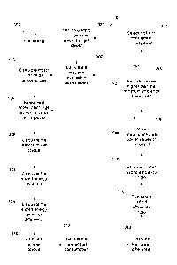
HEI processing 300 in Fig. 3 includes calculating a maximum evaluation
power level and a minimum evaluation power level (302) thus establishing a
range
of available power output values. The maximum and minimum evaluation power
levels generally correspond to operational characteristics of energy storage
system
134. eMachine 112, the current power output of engine 102, as well as other
related aspects of hybrid system 100. Because the HEI represents the trade-off
between burning fuel in the engine versus using electrical energy in eMachine
112,
the upper limit of the maximum evaluation power level, in one embodiment,
represents the electrical power level required to operate eMachine 112 at a
level
that would cause it to produce the same mechanical output power that is
currently
being produced by engine 102 burning fuel to provide a user requested output
torque.
However, this calculated electrical power value may exceed the maximum
power that can be delivered by energy storage system 134 or utilized by the
eMachine 112. For example, energy storage system 134 can only deliver, at
most,
some maximum power based on its current state of charge, temperature, and
various other operating parameters. Likewise, eMachine 112 can only utilize
electrical energy at a given maximum rate based on its design constraints and
therefore can only deliver some well-known maximum mechanical output power.
Therefore, transmission/hybrid control module 148 can determine the maximum
Date Recue/Date Received 2020-11-26
WO 2014/158848
PCT/US2014/020532
evaluation power level by, for example, using the minimum value of either the
discharge power limit of energy storage system 134, the maximum useable input
power of eMachine 112, or the power value resulting from converting the
mechanical power produced by the engine to an equivalent electrical power at
the
5 current user torque request. The minimum evaluation power level is
determined by
calculating a minimum operating consumption power level, such as at idle when
the system is under minimal load.
Using the maximum and minimum evaluation power levels, the
transmission/hybrid control module 148 calculates a plurality of motor
discharge
10 power values (303) representing the set of electrical energy levels for
which a
Hybrid Efficiency Index will be calculated. In one embodiment, the plurality
of
motor discharge power values is determined by incrementing the power level for
each discharge power in the set of values by a preset value or increment over
the
previous value. The increment may be adjustable and may he dependent on
aspects
of hybrid system 100 such as the smallest power adjustment to which inverter
132
and cMachine 112 are able to respond to. In another embodiment, the plurality
of
discharge power levels is determined by dividing the available range between
the
maximum and minimum discharge power by a preset number such as 100 or 50.
The transmission/hybrid control module 148 iterates through the plurality
of motor discharge power values (304) calculating the HEI for each motor
discharge power value given the current operator torque quest. To calculate
the
HEI, transmission/hybrid control module 148 calculates an electric motor
torque
(306) using the current motor discharge power value as the input power in the
calculation. In one embodiment, the electric motor torque is calculated by
converting the input power from electrical to mechanical energy and dividing
by
the motor speed. Other suitable calculations may be used as well.
A reduction in energy storage is also calculated (307) where the stored
energy reduction indicates the reduction in available energy that would result
from
withdrawing the input power from the energy storage device in order to create
the
calculated electric motor torque. The stored energy reduction includes the
electric
power consumed by the motor while also, for example, taking into account
losses
in energy storage system 134 resulting from the transfer of energy from energy
Date Recue/Date Received 2020-11-26
WO 2014/158848
PCT/US2014/020532
11
storage system 134 to eMachine 112. These losses include losses due to heating
caused by resistance to the transfer of energy. For example, where energy
storage
system 134 includes batteries, power losses in the batteries can be
characterized in
terms of resistance, power, and voltage as R * (PIE)2 where R is the
resistance of
the battery pack, P is the input power to eMachine 112 (the power withdrawn
from
the battery in this case), and E is the input voltage to eMachine 112.
A similar stored energy reduction calculation is performed using the
minimum evaluation power to determine the minimum stored energy reduction.
Both the minimum stored energy reduction, and the stored energy reduction are
used to calculate a stored energy reduction differential (309).
An engine torque for the engine is calculated (310) which is reduced by the
torque output calculated for the electric motor. In this way, the engine
torque
calculation includes the previously calculated electric motor torque
calculation
from stage 306 indicating that engine 102 reduces its torque output in
pmportion to
the torque produced by eMachine 112. Thus, both engine 102 and eMachine 112
work together to fulfill the operator power (i.e. torque) request and the
motor
torque operates as a replacement for some or all of the engine torque output.
A rate of fuel consumption for engine 102 is calculated at 312 for both the
current input power, and the minimum evaluation power. Fuel consumption rates
for a given engine speed, torque, and output power are generally well
characterized
by the manufacturer and made available to transmission/hybrid control module
148
from engine control module 146 as engine 102 is operating. These mappings are
used by transmission/hybrid control module 148 to determine the quantity of
fuel
used.
A fuel usage differential is calculated at 313 by, for example, subtracting
the rate of fuel consumption from the minimum evaluation fuel consumption rate
determined from the minimum evaluation power. In one embodiment of the Hybrid
Efficiency Index (HEI), the HEI is calculated (315) as the fuel usage
differential
calculated in stage 313 divided by the stored energy reduction differential
calculated in stage 309. The calculated Hybrid Efficiency Index is saved
(317), for
example, at least until an HEI has been calculated for all the motor discharge
Date Recue/Date Received 2020-11-26
WO 2014/158848
PCT/US2014/020532
12
power values. If more motor discharge power values remain to process (318),
the
HEI calculation repeats for another motor discharge power value at stage 304.
If all the motor discharge power values calculated in stage 303 have been
processed, the transmission/hybrid control module 148 determines if any of the
calculated HEI values saved in stage 317 are higher than a current minimum
efficiency threshold (320). If not, calculation of a new set of HEI values is
performed and processing begins again at stage 302. Processing the HEI loop
may
be prognumned or otherwise designed to execute multiple times per second, for
example 50 times per second, but may he executed more quickly such as 100
times
per second or even faster, or less quickly such as five or 10 times per second
or
slower depending on the embodiment and system constraints. Also, some time lag
may be incorporated into the transition from stage 320 to 302 when no I-1E1
values
are higher than the minimum efficiency threshold. In some embodiments it may
be
advantageous to wait some period of time before repeating the HET calculations
for
a new set of motor discharge power values.
HEI processing 301 completes with adjusting the eMachine 112 input
power if applicable. In one embodiment, if at least one of the HEI values
calculated in stage 315 and saved in stage 317 is higher than the minimum
efficiency threshold (320), the transmission/hybrid control module 148 selects
the
HEI value that is both higher than the minimum efficiency threshold and has
the
highest input power (321). The input power for the selected HEI value is used
by
the transmission/hybrid control module 148 as the new input power setting for
eMachine 112. The transmission/hybrid control module 148 then signals the
relevant components of hybrid system 100 such as inverter 132, energy storage
system 134, and eMachine 112 to operate eMachine 112 in the electric motor
mode
generating an output torque substantially equal to the input torque used in
the
calculation of the selected HEI value. At about the same time, engine control
module 146 is signaled by the transmission/hybrid control module 148 to reduce
engine output torque by the same amount thus trading engine 102 torque for
eMachine 112 torque. I-IEI processing then returns to stage 302 where a new
set of
1IEI calculations is made evaluating anew the most efficient trade-off between
Date Recue/Date Received 2020-11-26
WO 2014/158848
PCT/US2014/020532
13
electrical energy and fuel burn in relation to current requested torque output
and
the performance constraints of hybrid system 100.
As noted above, the calculation of the HEI values for a given set of motor
discharge power values is calculated repeatedly during the operation of the
hybrid
system 100, perhaps multiple times per second in some embodiments. However
other aspects of HEI processing include adjusting the minimum efficiency
threshold which operates to select only the best opportunities for using
electrical
energy (see stage 320) in place of burning fuel in engine 102.
For example, another aspect of HEI processing 300 is shown in Fig. 4 at
400 and includes adjusting the minimum efficiency threshold (or HEI target) to
ensure that regenerative energy is captured and not lost because of inadequate
available storage in energy storage system 134. HEI processing 300 seeks to
ideally maintain the minimum efficiency threshold just low enough so that
energy
expended over the entire trip or operating cycle is about equal to the
regenerative
energy captured during the trip. However, mismanagement of power stored in
energy storage system 134 may result in the loss of the opportunity to recover
energy during a regenerative braking event, for example, in the case where the
energy storage system is already full and no further energy can be recovered.
Therefore, in one embodiment of HET processing 300, the minimum efficiency
threshold is reduced where energy is being lost in regeneration. Reducing the
minimum efficiency threshold has the effect of increasing the likelihood
eMachine
112 will be used because it results in more evaluation power levels from stage
302
translating into candidate HEI values in stage 321 (See Fig. 3).
In the embodiment illustrated in Fig. 4, transmission/hybrid control module
148 determines if a regenerative braking event is starting (401) and if not,
processing continues as before. This determination can be made, for example,
by
detecting torque in transmission 106 coming from wheels 110 through drive
train
108. Such an event may occur during vehicle deceleration alone, or when
frictional
braking is applied as well. Further, such an event may occur anytime a torque
is
applied to eMachine 112 from the hybrid vehicle drive train 108 and
transmission
106.
Date Recue/Date Received 2020-11-26
WO 2014/158848
PCT/US2014/020532
14
If a regenerative braking event is occurring, (401) transmission/hybrid
control module 148 determines whether the energy storage system 134 is fully
charged (403), for example by communicating with energy storage system 134
over hybrid data link 202. If energy storage system 134 is fully charged,
transmission/hybrid control module 148 calculates the energy that will not be
recovered during the regenerative braking event (405). If the energy storage
system
is not fully charged (403), transmission/hybrid control module 148 calculates
the
energy that is recovered during the regenerative braking process (407) as
torque
from transmission 106 spins eMachine 112 operating in the generator mode to
produce electric power. When the regenerative braking event is complete (408),
transmission/hybrid control module 148 calculates whether the energy
unrecovered
is greater than the energy recovered (410). If not, HEI processing continues
at
stage 300. If the energy unrecovered is greater than a fraction K of the
energy
recovered (410) transmission/hybrid control module 148 accesses the previously
saved minimum efficiency threshold (412) and reduces the minimum efficiency
threshold (413). This reduction may be for example, an incremental reduction
by a
small scalar value such as 0.1 or 0.5, or some other value. In other
embodiments,
the reduction may be calculated depending on the current value of the minimum
efficiency threshold thus, for example, reducing the minimum efficiency
threshold
by a greater amount if the value is higher or by a lesser amount if it is
lower. The
modified minimum efficiency threshold is saved by the controller (415) and is
useable throughout HEI processing 300 such as in stage 320 when selecting HEI
values calculated from the set of evaluation power levels.
In another aspect, the minimum efficiency threshold may be adjusted using
an offset. In one embodiment, the offset is determined based on maintaining or
approximating a desired storage capacity in the energy storage system 134. For
example, for embodiment of the energy storage system 134 that includes one or
more battery cells, it may be well-known from the battery cell manufacturer
that
the batteries perform best when kept between, for example, 40% and 70%
charged.
Therefore an offset may be applied to the minimum efficiency threshold to
adjust
the threshold lower or higher to maintain this approximate state of charge in
energy
storage system 134. In another embodiment, the offset may be incorporated into
Date Recue/Date Received 2020-11-26
WO 2014/158848
PCT/US2014/020532
the operating logic of transmission/hybrid control module 148 if the offset is
maintained in place for an extended period of time. This process of
incorporating
the offset may occur automatically, such as by adaptive logic which, for
example,
automatically includes the offset into the minimum efficiency threshold
5 calculations after the offset has been maintained for a preset number
of days, or the
incorporation process may be manual manually activated when the logic in the
processor or processing circuit reprogrammed or reset by a technician.
In another aspect of HEI processing related to the capacity of energy
storage system 134, the transmission/hybrid control module 148 observes the
10 energy recaptured and adaptively learns the expected ratio of kinetic
energy that
can be recovered across the vehicle speed envelope. As the vehicle is moving,
the
algorithm can use the expected ratio to determine if adequate storage capacity
is
present at any given time. This aspect of HEI processing is also performed by
the
transmission/hybrid control module 148 and illustrated in Fig. 5 at 500. An
15 expected energy recovery is calculated at 501. In one embodiment, the
expected
energy recovery is calculated in transmission/hybrid control module 148 by
averaging recent recovered energy quotients where the recovered energy
quotients
are each calculated as the ratio of an actual recovered energy divided by a
maximum recoverable energy. The maximum recoverable energy can be
detei mined as a function of the mass and velocity of the vehicle, both of
which are
either made available to transmission/hybrid control module 148 by hybrid
system
100, or are calculated by transmission/hybrid control module 148.
Transmission/hybrid control module 148 determines if the expected energy
recovery is greater than the current storage capacity (503). If so, HEI
processing
continues at 300. If the expected energy recovery is less than the current
storage
capacity (503) then transmission/hybrid control module 148 checks to determine
if
the expected energy recovery is greater than the maximum storage capacity in
energy storage system 134 (505). If not, HEI processing continues at 300. If
the
expected energy recovery is greater than the maximum storage capacity (505),
the
previously saved minimum efficiency threshold is accessed from memory (506)
and transmission/hybrid control module 148 reduces the minimum efficiency
threshold (508) as discussed above. The reduced minimum efficiency threshold
is
Date Recue/Date Received 2020-11-26
WO 2014/158848
PCT/US2014/020532
16
also saved (509) for use throughout all aspects of HEI processing 300, for
example
in stages 320, 412, and 506.
In another aspect of I-1E1 processing 300, the transmission/hybrid control
module 148 seeks to maintain a minimum efficiency threshold that is as high as
possible. Energy is extracted from the energy storage system 134 to power the
vehicle or assist engine 102 using eMachine 112 at a given power level when
the
calculated HEI at that power level exceeds the current minimum efficiency
threshold. eMachine 112 will continue to provide some or all of the user's
torque
request until the HEI drops below the current minimum efficiency threshold.
Transmission/hybrid control module 148 can then calculate the quantity of
energy
expended during this particular propulsion event, and can also determine how
much, if any, of this energy would have been expended if the minimum
efficiency
threshold had been set to a predetermined evaluation efficiency threshold that
is
higher than the current minimum efficiency threshold. By comparing the energy
expended with the energy that would have been expended at the higher
evaluation
threshold, transmission/hybrid control module 148 can determine whether a
higher
minimum efficiency threshold will result in a more judicious use of available
electrical power resulting in a higher fuel efficiency.
One embodiment of the stages involved in using an evaluation efficiency
threshold to calculate adjustments to the current minimum efficiency threshold
are
illustrated in Fig. 6 at 600. r[he transmission/hybrid control module 148
accesses
the previously saved minimum efficiency threshold and a previously saved
evaluation efficiency threshold at 602. The actual energy usage is calculated
based
on information obtained from energy storage system 134 during propulsion
events
(604). In one embodiment, energy usage is calculated during the propulsion
phase
by integrating the storage discharge rate over time yielding a value
representing an
energy usage for the time the HEI was above the minimum efficiency threshold
and eMachine 112 was withdrawing power from energy storage system 134. The
transmission/hybrid control module 148 can then calculate the energy that
would
have been withdrawn from energy storage system 134 using the higher evaluation
threshold (605).
Date Recue/Date Received 2020-11-26
WO 2014/158848
PCT/US2014/020532
17
The higher evaluation threshold is used to determine whether the evaluation
threshold would have resulted in higher power expenditures. If the evaluation
energy and the actual energy expended are equal (606), HEI processing
continues
at 300. If the evaluation energy and the actual energy are not equal,
transmission/hybrid control module 148 determines if the evaluation energy is
greater than the actual energy withdrawn from energy storage system 134 at
stage
607. If so, transmission/hybrid control module 148 compares the expected
energy
recovery with the current storage capacity (609). If the expected energy
recovery is
not less than the current storage capacity, HEI processing continues at 300.
If the
expected energy recovery is less than the current storage capacity in energy
storage
system 134 (609), the minimum efficiency threshold is increased (611), for
example by some incremental amount, by a computed value as discussed above, or
set equal to the evaluation threshold, and the newly increased minimum
efficiency
threshold is saved to the controller memory (613). In this case, the minimum
efficiency threshold is raised because the energy that could have been
expended at
the higher evaluation threshold is greater than the energy that was expended,
and
energy storage system 134 can still hold more energy than it expects to
recover.
Therefore, transmission/hybrid controller 148 is justified in saving a little
more
energy, using a little less, and thus raises the minimum threshold.
Continuing with the stages at 600 in Fig. 6, if the evaluation energy is less
than the actual energy (607), transmission/hybrid control module 148 evaluates
whether the expected energy recovery is greater than or equal to the current
storage
capacity (615). If not, HEI processing continues at 300. If the expected
energy
recovery is greater than or equal to the current storage capacity (615), the
minimum efficiency threshold and the evaluation threshold are both reduced
(616),
for example, as discussed above, and the newly reduced thresholds arc saved in
the
memory in transmission/hybrid control module 148 (613) and HEI processing
continues at (300). In this case, the actual energy recovered is the same or
greater
than the current threshold, and energy storage system 134 likely cannot hold
the
energy the system expects to recover from regeneration. This indicates too
much
energy is being stored meaning the minimum efficiency threshold should be
Date Recue/Date Received 2020-11-26
87193440
18
reduced to increase the likelihood the excess energy will be expended rather
than wasted.
While the invention has been illustrated and described in detail in the
drawings and
foregoing description, the same is to be considered as illustrative and not
restrictive in character, it
being understood that only the preferred embodiment has been shown and
described and that all
changes, equivalents, and modifications that come within the spirit of the
inventions defined by
following claims are desired to be protected.
Date Recue/Date Received 2020-11-26