Note: Descriptions are shown in the official language in which they were submitted.
CA 03101589 2020-11-25
WO 2019/231485 PCT/US2018/051817
ACOUSTIC OTOSCOPE
CROSS-REFERENCE
[0001] This application claims the benefit of U.S. Non-Provisional Patent
Application Serial
No. 15/995,793, filed June 14, 2018, which application is incorporated herein
by reference.
FIELD OF THE INVENTION
[0002] The present disclosure relates to an otoscope for characterization
of fluid on the
proximal surface of a tympanic membrane in a mammalian ear. In particular, the
present
disclosure relates to making a viscosity measurement of the fluid proximal to
the tympanic
membrane by measuring the time and frequency related displacement of a
tympanic membrane
in response to an acoustic volume excitation applied to an ear canal.
BACKGROUND OF THE INVENTION
[0003] Acute Otitis Media (AOM) is a common disease of the inner ear,
involving tissue
inflammation and fluidic pressure which impinges on the tympanic membrane.
Acute Otitis
Media may be caused by a viral infection, which generally resolves without
treatment, or it may
be caused by a bacterial infection, which may progress and cause hearing loss
or other
deleterious and irreversible effects. Unfortunately, it is difficult to
distinguish between viral or
bacterial infection using currently available diagnostic devices, and the
treatment methods for the
two underlying infections are quite different. For bacterial infections,
antibiotics are the
treatment of choice, whereas for viral infections, the infection tends to self-
resolve, and
antibiotics are not only ineffective, but may result in an antibiotic
resistance which would make
them less effective in treating a subsequent bacterial infection. It is
important to accurately
diagnose acute otitis media, as AOM can be a precursor to chronic otitis media
with effusion
(COME), for which surgical drainage of the effusion and insertion of a tube in
the tympanic
membrane is indicated.
[0004] The definitive diagnostic tool for inner ear infections is
myringotomy, an invasive
procedure which involves an incision through the tympanic membrane, withdrawal
of fluid, and
examination of the effusion fluid under a microscope to identify the
infectious agent in the
effusion. Because of complications from this procedure, it is only used in
severe cases. This
presents a dilemma for medical practitioners, as the prescription of
antibiotics for a viral
infection is believed to be responsible for the evolution of antibiotic
resistance in bacteria, which
may result in more serious consequences later in life, and with no efficacious
treatment outcome,
as treatment of viral infectious agents with antibiotics is ineffective. An
improved diagnostic
tool for the diagnosis of acute otitis media is desired.
-1-
CA 03101589 2020-11-25
WO 2019/231485 PCT/US2018/051817
OBJECTS OF THE INVENTION
[0005] A first object of the invention is a device for estimation of
tympanic membrane
mobility through the introduction of a volume displacement excitation into a
sealed ear canal, the
measurement of eardrum displacement performed using the proxy of measured
pressure in the
tympanic membrane.
[0006] A second object of the invention is a method for determination
viscosity of fluid
adjacent to a tympanic membrane by application of a volume displacement
excitation and
measurement of time and frequency domain characteristics of the pressure
developed as a proxy
for tympanic membrane displacement.
[0007] A third object of the invention is an apparatus for characterization
of a fluid adjacent
to a tympanic membrane, the apparatus having a speculum tip for sealing an ear
canal, a volume
displacement source for changing a volume of an ear canal, and a pressure
measurement for
determining the effect of the displacement change on measured external ear
canal ear pressure,
thereafter forming an effusion metric based on the amplitude and phase of the
pressure response
versus time or, equivalently, versus frequency.
SUMMARY OF THE INVENTION
[0008] In one example, a controller is operative to change the air volume
of a chamber which
is sealed to, and coupled into, an ear canal. The air volume change coupled to
the ear canal is
referred to as AV(t), a function of time. During the interval of time when the
air volume change
is occurring, a continuous or discrete series of pressure measurements are
made, and the air
volume change is compared to the pressure measurements in at least one of a
time domain
response, or a frequency domain response. In this manner, the extent of
displacement of a
tympanic membrane in response to the air volume change may be determined, and
a viscosity
metric may be formed. In alternative embodiments, a pressure modulation may be
used which
introduces or removes air in a fixed volume to increase or reduce the tympanic
membrane
pressure.
[0009] In another example, a process for determining the existence or
extent of acute otitis
media has a cyclic volume displacement step whereby a chamber having a
dynamically
adjustable internal volume is coupled to a sealed ear canal such as through a
speculum tip, the
speculum tip including a pressure measurement sensor, the process comparing
the change in
volume as an excitation source coupled to the ear canal to the change in
pressure measured in the
ear canal as a response, the time domain static and dynamic response
characterized to determine
at least one of a frequency response or a time response of the tympanic
membrane, the frequency
-2-
CA 03101589 2020-11-25
WO 2019/231485 PCT/US2018/051817
or time response mapped to a mobility metric, from which the presence,
absence, or composition
of a fluid adjacent to the tympanic membrane may be determined.
[0010] Aspects of the present disclosure provide, an acoustic otoscope. An
acoustic otoscope
may comprise a speculum tip for coupling to an ear canal; an excitation source
for generation of
dynamic volume or pressure, the excitation source dynamic volume or pressure
coupled to the
speculum tip, the excitation source responsive to an input control; a pressure
sensor for
estimation of pressure in the speculum tip and returning a series of
measurements; a controller
coupled to the excitation source input control and also coupled to receive
pressure sensor
measurements; the controller thereby generating said excitation source input
control and
acquiring an associated series of pressure measurements in response; the
controller forming a
series of difference values by subtracting a scaled pressure measurement
output from an
excitation input; an effusion metric derived from the series of difference
values and having an
increased effusion metric value where at least one of: the series of
difference values has an
elevated difference amplitude following a step change in pressure or volume
compared to
subsequent difference values; the series of difference values has an elevated
difference amplitude
for low frequency pressure or volume excitation compared to the difference
amplitude for high
frequency pressure or volume excitation.
[0011] In some embodiments, the scaled pressure measurement may use a
scaling factor
which causes the pressure measurement to have a mid-point value substantially
equal to the
excitation source mid-point input value. In some embodiments, thee excitation
source input
waveform may be sinusoidal. In some embodiments, the excitation source input
waveform may
be trapezoidal. In some embodiments, the series of difference values may be
averaged over at
least 4 acquisition cycles. In some embodiments, the sinusoidal excitation
source input
waveform and pressure sensor measurement waveform may be acquired over several
frequencies
to determine a corner frequency. In some embodiments, an effusion metric may
be formed from
comparison of the corner frequency to threshold frequencies for a normal
tympanic membrane, a
viral fluid adjacent to a tympanic membrane, and a mucoid fluid adjacent to a
tympanic
membrane.
[0012] In some embodiments, the excitation source may comprise a moveable
diaphragm, a
moveable piston, or a source of differential pressure coupled to a speculum
tip with a hose. In
some embodiments, the excitation source may comprise a diaphragm or piston
enclosed in the
speculum tip or speculum tip mount. In some embodiments, the excitation source
may be
coupled to a source of greater or lower air pressure through one or more
valves controlled by the
excitation input.
-3-
CA 03101589 2020-11-25
WO 2019/231485 PCT/US2018/051817
[0013] Aspects of the present disclosure provide an acoustic otoscope. The
acoustic otoscope
may comprise a speculum tip having a seal for closure to an ear canal; an
excitation source
changing a pressure or a volume and coupled to the speculum tip, the
excitation source having an
input; a pressure sensor coupled to the speculum tip and providing a pressure
measurement
output; a controller generating an excitation source input waveform, the
controller also coupled
to the pressure sensor and receiving a pressure measurement output waveform;
the controller
generating the excitation input source waveform and simultaneously comparing
the pressure
measurement with the excitation waveform to form an effusion metric.
[0014] In some embodiments, the excitation source may cause least one of a
volume change
or a pressure change. In some embodiments, the excitation source may be a
moving diaphragm.
In some embodiments, the effusion metric, after establishing a monotonic
sequence of a first
threshold, second threshold, and third threshold, may be a non-diagnostic
speculum tip leak
detection for at least one of: a transfer function for pressure measurement to
excitation waveform
is below the first threshold; a high frequency transfer function for pressure
measurement to
excitation waveform is below the third threshold; a negative pressure response
is detected when
the excitation source is a volume modulating piston or diaphragm which is
returned to an
original position; a pressure measurement change is not detected in response
to an excitation
waveform.
[0015] In some embodiments, the volume excitation waveform may be a sinusoid
and the
VP(f)
effusion metric is based on a corner frequency in the frequency response
function ¨Ali(f) where:
AP(f) is the pressure amplitude for a plurality of discrete frequencies; AV(f)
is the volume
excitation amplitude for a plurality of discrete frequencies; and the corner
frequency is a
frequency f for which the response function is less than 1/V2 of the value at
a higher frequency.
In some embodiments, the volume excitation waveform may be a trapezoidal
waveform and the
effusion metric is based on the difference between the volume excitation
waveform and the
pressure measurement waveform where the pressure measurement waveform is
scaled to a
midpoint of the waveform. In some embodiments, the midpoint may be the
earliest of a point in
time where the slope of the pressure measurement waveform changes to 1/4 or
less of its initial
value, or a half interval point, whichever occurs sooner. In some embodiments,
the effusion
metric may be based on the maximum amplitude of the difference waveform before
the
midpoint.
[0016] Aspects of the present disclosure provide a method for forming an
effusion metric.
The method may be operative on a speculum tip having an inspection aperture
for coupling to an
ear canal and tympanic membrane to be characterized. The speculum tip may be
coupled to a
-4-
CA 03101589 2020-11-25
WO 2019/231485 PCT/US2018/051817
pressure measurement sensor for measuring a pressure in the speculum tip and
also a pressure
excitation generator for modulating a pressure in the speculum tip. The method
may comprise
forming a pressure excitation coupled to the speculum tip; measuring a
pressure response;
based on a transfer function of pressure response to pressure excitation,
making a determination
of at least one of: a pressure seal leak; a healthy tympanic membrane; a
tympanic membrane
coupled to a watery liquid a tympanic membrane coupled to a comparatively
thick bacterial
fluid.
[0017] In some embodiments, the determination may be made based on comparing a
first
measurement of a healthy ear to a different ear. In some embodiments, the
determination may be
based on a characterization of at least one of: a frequency response corner
frequency, a time
delay to a step response, or parametric fitting of coefficients to a decay
equation. In some
embodiments, the decay equation is 4(0 = k1 (1 ¨ e 1) or Pf (t) = k2 (¨rt 2) .
INCORPORATION BY REFERENCE
[0018] All publications, patents, and patent applications mentioned in this
specification are
herein incorporated by reference to the same extent as if each individual
publication, patent, or
patent application was specifically and individually indicated to be
incorporated by reference.
BRIEF DESCRIPTION OF THE DRAWINGS
[0019] The novel features of the invention are set forth with particularity
in the appended
claims. A better understanding of the features and advantages of the present
invention will be
obtained by reference to the following detailed description that sets forth
illustrative
embodiments, in which the principles of the invention are utilized, and the
accompanying
drawings of which:
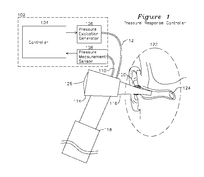
[0020] Figure 1 shows a diagram of a pressure response controller coupled
to a human ear
canal.
[0021] Figure 2 shows amplitude transfer plots and phase transfer plots for
various effusion
conditions.
[0022] Figure 3A shows a plot of a first volume excitation and exemplary
response.
[0023] Figure 3B shows a plot of a second volume excitation and exemplary
response.
[0024] Figure 4 shows a plot of a third volume excitation and exemplary
response.
[0025] Figure 5 shows a plot of a forth volume excitation and exemplary
response.
[0026] Figure 6 shows a block diagram of an otoscope measuring a tympanic
membrane
displacement in response to a displacement source.
-5-
CA 03101589 2020-11-25
WO 2019/231485 PCT/US2018/051817
DETAILED DESCRIPTION OF THE INVENTION
[0027] Figure 1 shows an otoscope 130 which includes a speculum tip 116 for
insertion into
an ear canal of a subject to be characterized. A lens 126 is coupled to an
optical unit 114 which
provides for examination of the outer ear as is provided by a prior art
otoscope such as the Welch
Allyn 25070-M. A pressure excitation generator 106 couples a volume change
from an
excitation generator through hose 112 to the speculum tip 116, and a pressure
measurement hose
to a pressure sensor 108 provides a measurement of pressure change in the
speculum tip 116
from the excitation generator change in volume. It may be preferable for the
speculum tip 116 to
be sealed where it attaches to the optical unit 114 to minimize the volume
being excited to
include only the ear canal and speculum tip 116 volume, or the speculum tip
116 may be sealed
to the ear canal in other locations including the concha and tragus at the
entrance to the ear canal
or in any location which completes a seal to the ear canal.
[0028] When inserted into the ear canal of a subject (detail 122), a
conformable seal 120 may
be used which comfortably seals the speculum tip 116, thereby providing
effective coupling of
volume changes generated by volume excitation generator 106 to the inner ear
and tympanic
membrane 124. Volume (or pressure) excitation generator 106 may be any of: a
voice coil
integrated with a movable diaphragm, a diaphragm coupled to a piston actuator,
or any
mechanism modulating a volume or introducing an external pressure source which
is coupled to
speculum tip 116 to cause a change in pressure (such as by a change in
enclosed volume or
introduction and removal of a gas such as air from a fixed volume) which
couples the change in
pressure into the speculum tip 116 and to the tympanic membrane. In the
present description, a
volume modulating device such as a diaphragm or piston is described, however
it is understood
that the pressure change generated by the pressure excitation generator 105
may be formed by
any volume displacement method. The volume change is intended to result in a
very slight
change in position of the tympanic membrane 124. If there is no fluid present
behind the
tympanic membrane 124, the tympanic membrane is able to move freely and
accommodate
slowly changing (low frequency) changes in volume with negligible changes in
pressure. If fluid
is present behind the tympanic membrane 124, the tympanic membrane will
exhibit reduced
displacement for high frequency pressure change. Additionally, for a tympanic
membrane which
is coupled to watery viral fluid or mucoid infectious fluid, the tympanic
membrane may be less
able to respond to high frequency changes in volume, which result in greater
pressure changes
for a given incremental volume change when fluid is present adjacent to the
less mobile
tympanic membrane, and the greater the mass of the fluid present, the greater
the constriction for
movement of the tympanic membrane at lower frequencies, resulting in greater
induced
pressures at greater frequencies.
-6-
CA 03101589 2020-11-25
WO 2019/231485 PCT/US2018/051817
[0029] When fluid is adjacent to the tympanic membrane, the mobility of the
tympanic
membrane is reduced, which results in greater developed pressure for a given
change in volume
at high frequencies. This is shown in Figure 2 frequency response plot showing
differential
pressure change (AP) divided by differential volume change (AV) as a function
of frequency,
scaled to unity for AP/AV of an immobile TM. A pressure change vs volume
change response
plot for a healthy ear is shown in plot 208, which develops minimal pressure
changes for
incremental volume change at low frequencies because the mobile tympanic
membrane without
adjacent fluid coupling tracks displacement changes of the excitation
generator, so the volume of
the system remains relatively fixed and minimal pressure change results. Fluid
adjacent to the
TM which adds mass and restricts movement of the TM at higher frequencies
results in
incremental speculum 116 pressure at lower frequency 212 of plot 206, and
"glue ear" where the
TM is immobile results in the response plot 204 with associated corner
frequency 210, where
changes in volume result in greater incremental pressures.
[0030] The plots of Figure 2 show transfer functions of pressure/volume
versus frequency
such as a sinusoidal volume modulation measured as a transfer function of
pressure versus
frequency. Each of the plots which has a corner frequency where the transfer
function flattens as
the frequency is increased. Low frequency volume changes which do not produce
a pressure
change in the ear indicate the tympanic membrane is moving freely at that
frequency, and as the
tympanic membrane is unable to move freely because of increased inertia of
adjacent fluid
coupling, the pressure increases, as shown in the plots of figure 2 for
various states of the
tympanic membrane. For example, a healthy tympanic membrane which is free to
move over a
wide range of frequencies without resistance is shown as waveform 208 with a
corner frequency
of 214. Where watery fluid from a viral infection is present behind the
tympanic membrane, the
mobility of the tympanic membrane 124 is reduced such that it no longer is
able to respond to
moderate frequencies (212) and develops speculum pressure modulations at these
frequencies, as
indicated by the pressure/volume response plot 206. The final stage of ear
infection, where
bacterial matter with greater density than viral watery fluid collects on the
tympanic membrane
and becomes "glue ear", further reduces the amplitude response and frequency
range and is
shown with plot 204, indicating that the tympanic membrane does not move in
response to
volume/pressure excitations except at the lowest pressure excitation
frequencies 210. Each
corner frequency 210, 212, and 214 is determined by the mass and volume of
fluid which
restricts the TM movement.
[0031] Figure 3A shows another perspective and method for characterization
of the TM using
a frequency domain excitation plot 302 (a sinusoidal volume change) with
corresponding
pressure (used as a proxy for tympanic membrane position) 306. By examination
of the
-7-
CA 03101589 2020-11-25
WO 2019/231485 PCT/US2018/051817
amplitude of measured pressure plot 306 and phase delay 310 for a particular
period 304, and
repeating the measurement at other frequencies, a plot of phase delay 310 and
amplitude may be
derived from the response waveform 306. In another example embodiment, the
phase and
amplitude responses may be collected in by using a chirped frequency
excitation which varies in
period for successive repeated cycles, thereby measuring the tympanic membrane
displacement
response (via pressure) to a volume excitation (chirped frequency
displacement) in a single
frequency sweep. The transfer function for the tympanic membrane may be
determined as the
familiar plot of amplitude of 306 normalized to the amplitude of waveform 302
with phase delay
310 expressed in angle, both measured as a function of frequency. The transfer
function
amplitude and phase may be used clinically where thresholds are established
for frequencies
where the amplitude transfer function has dropped 3dB or 6dB, or the phase
lags by 45 degrees,
to establish frequency break points, where the frequency break point may be
used as a mobility
metric, with a high frequency break point indicating normal ear, a lower
frequency break point
indicating effusion, and a yet lower frequency break point indicating glue
ear.
[0032] Figure 3B shows an alternative time domain response, where a step
change 320 in
volume is momentarily applied, and a pressure response plot 326 is observed,
similarly having a
time domain delay 324, as well as some rounding of the response associated
with loss of high
frequency components from the mechanical inertia of the tympanic membrane and
adjacent
fluid, with the time delay 324 and extent of rounding associated with mobility
of the tympanic
membrane, which is also a proxy for whether no effusion, watery effusion, or
dense bacterial
mucoid effusion is present. The measurement metric using the response 326 of
figure 3B may
use time response thresholds to establish health of the tympanic membrane,
where a
comparatively long time response 324 indicates glue ear, a shorter response
indicating effusion,
and a yet shorter response indicating a normal ear.
[0033] In another measurement method, a trapezoidal pressure excitation 402
is applied by
the controller 104, and the measured pressure 406 in the speculum tip 406 is
examined to
determine a settling time ti 404 where the temporal rate of change in pressure
is reduced to an
exemplar 1/4 of its initial rate of change value, or is selected to be a
particular fixed time 404,
whichever occurs first. A scaling factor k is applied to the measured pressure
waveform 406
such that the at time ti 404, k*AP(t1) = AV(t1). When k is determined from
this measurement, a
difference waveform dP(t) 408 is computed, such that dP(t)= AV(t) - k*AP(t).
Waveform 408 is
examined, and a peak value dP(max) is determined and tested according to the
following criteria
(where the first threshold, second threshold, and third threshold are
established as a
monotonically increasing sequence of thresholds):
if dP <Ti (a first threshold), then it is likely no fluid is present;
-8-
CA 03101589 2020-11-25
WO 2019/231485 PCT/US2018/051817
if Ti <= dP <= T2 (a second threshold), it is likely watery fluid is present;
if T2 <= dP <= T3 (a third threshold), it is likely mucoid fluid or glue ear
is present.
[0034] In another example, the difference dP(t) is formed by averaging
several instances of
AA(t) and AP(t).
[0035] In another example, the volume excitation AA(t) rise time Tr 401 is
varied over
several successive cycles in sets, each set of pressure excitations being
identical with the
pressure response of each cycle averaged to provide a composite AP(t) to
provide both a reliable
pressure response for each set of cycles, as well as vary the rise time Tr 401
over different sets of
measurement cycles to characterize the tympanic membrane for a variety of
pressure excitation
rise times.
[0036] In another example, delta V rise time 401 is reduced to a minimum
and the pressure
response rise time 405 from 0 to tr and fall time 406 from tr to t2 are
examined and fit to a curve.
For example, it may be possible to fit pressure rise time response 405 (or t
difference rise time
409) to Pr (t) = kl(1 ¨ e ¨t ) and the fall t time 408 to Pf = k2(1 ¨ e¨t )
r1 rZ
where:
Pr(t) is rise time of 405 or 409 from 0 to tr;
Pf(t) is the fall time of 406 or 408 offset to 0 at t2;
t is time (x axis of the plots);
kl is an amplitude scaling constant;
Ti is the rise time coefficient to be determined by curve fit matching, having
units
of time;
T2 is the fall time coefficient to be determined, by curve fit matching,
having the
units of time.
After determination of kl and Tl, or k2 and T2 from at least one of
corresponding
waveforms 408, 409, 405, or 406, it is then possible to form an effusion
metric, where a
comparatively longer Ti or T2 and a comparatively greater kl and k2 indicates
less likelihood of
effusion or glue ear, and a comparatively shorter Ti or T2 indicates greater
likelihood of
effusion, yet shorter Ti or T2 indicating glue ear for large values of kl and
k2, and where
comparatively smaller values of kl and k2 may be used to indicate a poor seal
(or perforated
TM), particularly when accompanied by comparatively short Ti or T2.
[0037] In another example, a burst of sinusoidal volume excitation 302 of 5
cycles or more is
provided as AV(t), each cycle of the burst being used to average the measured
pressure
waveform AP(t) for a single cycle at frequency f to provide a pressure
response point for a
VP(1)
particular frequency fl, thereafter computing the frequency transfer function
¨Aliul) for each
-9-
CA 03101589 2020-11-25
WO 2019/231485
PCT/US2018/051817
frequency f The resultant transfer function response corner frequencies 214,
212, 210 of Figure
2 may thereafter be similarly used as threshold frequencies to determine
normal tympanic
membrane response, watery fluid behind the tympanic membrane, and mucoid or
glue ear
tympanic membrane response, respectively.
[0038] Each of the above methods as described for Figure 2, Figure 3A, Figure
3B, Figure
4, and Figure 5 may be used in a differential method, by comparing results
from a left and right
ear, in the case where ear infection of only one ear is clinically suspected.
The differential
comparison method of a healthy appearing ear and an ear suspected of infection
may provide
normalization of diagnostic thresholds compared to models developed from the
general
population. For example, a factor of 2 difference in a frequency break point
of Figure 2 or
Figure 3A, or a factor of 2 difference in time response of Figure 3B or Figure
4 between a
presumed healthy and suspected infected ear may be used to establish effusion,
and a factor of 4
or greater may be used to establish glue ear.
[0039] In
another embodiment, the signatures of the pressure responses are examined for
evidence of a seal 120 leak. Where a pressure leak to the ear canal is
present, the high frequency
transfer is adversely affected, if the seal leak is large enough, no pressure
will be measured in
response to a pressure excitation. An example of a speculum tip leak is shown
in the pressure
plots 420 and 422 of Figure 4, where the change in piston/diaphragm volume 402
causes a
transient positive pressure 420 followed by a transient negative pressure 422
when the
piston/diaphragm moves in the opposite direction. The duration of the measured
pressure
waveform 420 and 422 may be examined to determine any of several conditions
which may
identify a poor speculum tip seal 120, not limited to:
1) a shortened pressure time response which is less than a duration of the
volume change
excitation;
2) the absence of a pressure response during a volume change excitation;
3) A negative pressure response 422 in response to the volume modulating
piston/diaphragm being returned to its original position.
[0040] Figure 6 shows an alternative tympanic membrane displacement
measurement system
comprising piston (or diaphragm) 606 which is sealed 604 to create a closed
chamber 608 with
the displacement volume coupled via hose 112 to speculum tip 116 with optical
viewer 126.
Piston actuator 602 (which may be a voice coil actuator or other
electromagnetic actuator) causes
piston 606 to move along the axis of chamber 608, with the displacement
measured by sensor
614 coupled to displacement measurement 618. A central controller 601 issues
commands for
the piston actuator 602 to cause the piston 606 to modulate position, with the
displacement
measured 618 and reported to controller 601. The controller 601 also reads a
pressure
-10-
CA 03101589 2020-11-25
WO 2019/231485 PCT/US2018/051817
measurement 616 of the pressure developed in the speculum tip 116 delivered
from chamber 608
to the speculum tip 116 via hose 112.
[0041] In an example embodiment, the piston diameter 606 is selected to
have the same
approximate diameter of a pediatric (or adult) tympanic membrane. The piston
606
displacement is modulated and pressure 110 measured. For minimal pressure
change and with a
sealed system, the output value of displacement measurement 618 may be
regarded as a proxy
for the tympanic membrane movement. Accordingly, for movement of the piston
608 which
generates a minimal change in measured pressure 616, the piston 606
displacement may be
regarded as a proxy for the movement of the tympanic membrane. In one example,
the piston
606 displacement is a swept frequency and a break point in the measured
pressure measurement
616 frequency response is noted, this frequency break point represents the
excitation frequency
where the mobility of the tympanic membrane 124 is adversely affected by the
mass of adjacent
fluid which is preventing the high frequency modulation of the tympanic
membrane 124.
Alternative diaphragm pressure actuator 603 is shown in view 650, where a
voice coil 660 with
leads 658 is actuated when a current is developed which causes attraction or
repulsion with
permanent magnet 656, thereby displacing diaphragm 652 with respect to
flexible support 654
which provides high frequency response for diaphragm 652 in enclosed volume
608, with
coupling to speculum tip 610 as before, or the excitation generator may be
enclosed in speculum
tip 116 of figure!, or adjacent enclosure 114.
[0042] The illustrative examples are for understanding the invention, the
scope of which is set
forth in the claims which follow.
[0043] While preferred embodiments of the present invention have been shown
and described
herein, it will be obvious to those skilled in the art that such embodiments
are provided by way
of example only. Numerous variations, changes, and substitutions will now
occur to those
skilled in the art without departing from the invention. It should be
understood that various
alternatives to the embodiments of the invention described herein may be
employed in practicing
the invention. It is intended that the following claims define the scope of
the invention and that
methods and structures within the scope of these claims and their equivalents
be covered thereby.
-11-