Note: Descriptions are shown in the official language in which they were submitted.
Doc. No. 328-6 CA
SYSTEM AND METHOD FOR EXCAVATING AND CONSTRUCTING A
SHORING SUPPORT WALL AND WATER MANAGEMENT SYSTEM
FIELD
This invention relates generally to the top-down excavation and construction
of a
waterproof shotcrete wall for use as a shoring wall and as a permanent water
management
system for lessening the carbon footprint on construction sites.
BACKGROUND
In the construction of in-ground foundation walls for large buildings, it is
typical to dig
out and excavate the earth to the desired depth of the foundation while
building shoring
infrastructure suitable to the proposed final installation and then build up
the foundation
walls from the bottom up. The use of temporary shoring structures are
necessary to
prevent cave-ins of the earth adjacent to the excavation and add to the cost
and time
required to construct the final installation. Most temporary shoring walls are
constructed
as the site is excavated to facilitate the proposed works. Construction
industry methods
typically incorporate a two-step process utilizing temporary lagged soldier
beams
cantilevered, rakered, or tie back supported, ready-mix poured in place
concrete caissons,
sheet piling, soil nailing, plate girders, or incrementally placed reinforced
structural
shotcrete to restrain the soil during excavation until a peitnanent structure
can be built. A
major problem with these temporary structures is that water leaks through
walls' ties and
joints. Water may come from the excavation reaching the water table, or it may
come
from cutting into smaller glacial deposits upon excavation. The flow of water
may be
negligible or it may be unexpectedly large. Accurately estimating the exact
amount of
water that may seep into a construction excavation site is challenging.
Hydrogeologist's
reports are often overstated, indicating more water than is actually present,
and rarely
accurately represents the final flow of groundwater that will result from a
particular
excavation. Engineers often 'assume' high recharge to avoid responsibility and
potential
insurance claims. In response to this concern, water management installations
commonly
1
Date Recue/Date Received 2020-12-04
Doc. No. 328-6 CA
known as "bath-tubs" are installed to manage the hydrogeological challenges
associated
with the site outside of and not inclusive of the shoring wall installations.
Constructing a
large concrete raft-slab bathtub to accommodate expected water based on a
hydrogeologist
report may cost several millions of dollars or more, depending on the size of
the site. If the
hydrogeologist's report is inaccurate and overly conservative, this extra
expense of
overbuilding a raft-slab to accommodate a large flow of water from excavation
may be
unnecessary. The added financial burden and heavy environmental toll for this
type of
construction may not even be required, but only after the fact is this
realized when the
flow of groundwater is less than the amount predicted.
What is required, is a less expensive, more environmentally friendly solution
to shoring
walls and managing an unknown or imprecise expected quantity of ground water
in an
environmentally sensitive manner.
A preferred and more green solution would be to hold back and prevent
groundwater from
entering the excavated site. Not only would it save on the cost of building a
costly
concrete tub-like structure to accommodate the ingress of water from the
excavation, it
would save on pumping large quantities of greywater and groundwater into the
municipal
sewer system, which in itself has a large financial and environmental cost.
Providing a
wall that can hold back water or allow a small controlled flow to the
excavated area that
could be used locally would be a tremendous advantage. Of course, at the same
time, it is
preferred not to overbuild the shoring wall and it must be suitable for
holding back an
unexpected large flow of water in the instance that this occurs.
Therefore, most excavation shoring systems have not suitably addressed this
problem. In
fact, many of these systems exemplify the problems described hereinabove.
United States Patent 8,635,833 in the name of Anderson entitled "Top-down
method for
constructing below-grade structures" describes a system having a waterproof
membrane
between a concrete mudsill wall and a final concrete wall. Although the '833
patent
provides a substantially waterproof barrier between two walls so that the
inner wall
2
Date Recue/Date Received 2020-12-04
Doc. No. 328-6 CA
furthest from the ground being excavated provides a dry support wall, a trough
at the base
of the wall closest to the excavated wall collects and carries water to a
water collection
system or piping to carry the water away. Constructing a first mudsill wall
followed by a
waterproof membrane with a final outer wall of concrete is costly and does not
address
alternative solutions for managing the flow of water from behind the wall in a
temporary
construction phase and a permanent final phase. Furthermore, this is not a
particularly
environmentally sensitive solution.
When water from the water table flows out from beneath a support wall, as in
Anderson's
disclosure in the '833 patent, and if the flow is considerable, a dewatering
plan should be
implemented which provides a protocol for handling the outflow. Dewatering can
affect
the soil from which the water is draining, thereby affecting lands adjacent to
the
excavation site. The instant invention described hereafter provides a method
of managing
water and lessening heavy flows that would otherwise be present. Lessening
heavy flows,
has multiple advantages. Large amounts of water do not have to be pumped off
and
treated; and, ground adjacent to the site does not have its water table
altered significantly
which can have profound deleterious effects. Thus both of these deleterious
environmental
consequences can be lessened or avoided.
Due to the errors, and over estimating of presence of ground water by
hydrogeologists, it
would be advantageous to build a shoring wall which serves as a groundwater
management system, obviating the need for an expensive concrete bathtub to be
built
which has little or no use after the water collected is pumped out and which
has very high
environmental and material costs. Furtheimore providing a raft-slab bathtub to
collect
.. water as has been done in the past, requires excavating large amounts of
fill which is again
deleterious to the environment. This is not required using our invention.
Accordingly, it can be seen that a need exists for an improved method for
constructing a
temporary drained shoring and final waterproofing support wall system.
3
Date Recue/Date Received 2020-12-04
Doc. No. 328-6 CA
SUMMARY
Advantageously a single permanent waterproof shotcrete shoring wall is
provided
constructed in-situ using a top downward construction; the initial waterproof
wall allows
for a curtain grout application about the base, to seal off water after an
assessment of flow,
if the rate of flow exceeds a predetermined amount. Another feature of this
system is that
in instances where the water flow from behind the wall is negligible or
acceptable, that is,
less than the predeteimined amount, no curtain grouting is applied; and this
negligible
flow can be used in local applications, for gardens and other local green use.
Thus, this
negligible or acceptable amount of water flow, can be directed to green
applications where
the ground/stoim water is utilized rather than entering the municipal sewage
system.
Constructing a substantially waterproof wall down to a depth where 'true' flow
is
measured, and having the option of applying curtain grouting at the base to
seal off the
flow, is an environmentally "green" solution compared to constructing double
walls with a
waterproof membrane therebetween, or installing a large and thick concrete
slab bathtub
to resist water pressure between footings and slabs and later pumping the
water to a
municipal drain. Building a single peimanent waterproof shoring and support
wall in
accordance with this invention allows for a choice, dependent upon a flow of
water
coming from behind a wall. There are numerous ways in which the flow can be
measured.
For example, a catch basin can be placed at the bottom of the wall in a
particular region,
for example spanning a bay. In this instance the amount of water collected
over a period
of time can be measured and if the amount collected exceeds an acceptable
amount,
chemical curtain grouting can be used. Of course there are a myriad of other
ways in
which flow can be deteimined. If sealing is not required, dependent on water
flow,
sealing is not provided and substantial costs and materials are saved compared
to
conventional methods of building a concrete bathtub to capture and hold back
water. This
solution of building a drained temporary shoring wall for contingency, so that
the wall can
be waterproof, allows for the containment of flow that may result when
chemical curtain
grouting is applied. Notwithstanding, the construction of a wall that is
waterproof and
which is designed to hold back significant amounts of water is not trivial,
and a novel and
inventive method of construction and structure is described hereafter.
4
Date Recue/Date Received 2020-12-04
Doc. No. 328-6 CA
Chemical curtain grouting is most commonly used in industrial and civil work
where
excavation costs are extremely high, such as subways, tunnels, bridges,
manholes,
seawalls, and vaults, etc. However, chemical curtain grouting is also used in
the
restoration of older foundations ground improvement. Examples of chemical
grouting can
be found in United States patents 5,026,215, 8,272,811 and 10,106,943.
It may seem counterintuitive to build a wall that can withhold substantial
amounts of
water when the actual amount of water that may present upon excavation is
unknown and
may be a lesser amount than predicted by hydrogeology reports. However, by
doing so,
this method allows for an even larger amount of water specified in a
hydrogeology report
to be prevented from flowing and pooling when curtain grouting is applied. The
curtain
grouting can be applied in such a manner as to essentially stop the flow of
water or to
limit the flow in a controlled manner. The grouting is applied by injecting a
polymer
concrete mix into rows of holes at high pressure into locations in the ground.
Thus, a shoring wall is built in a multi-stage process as described hereafter
wherein, in a
first stage, the wall is constructed in a top down excavation and is
waterproof and in a
second stage a measuring device measures the outflow of water from the base of
the wall
built in the first stage. In a particular embodiment a deteitnination is made
in dependence
upon the measured flow and if the flow exceeds a predeteitnined amount, a
third stage is
enacted, where curtain grouting is applied. Although in some instances, the
waterproof
wall built in the first stage, may be considered by some as overbuilt, if
there is little or no
water present, we have found that this is a much less costly method and is an
environmentally more sound choice than typical shoring wall solutions that in
a temporary
functionality holds back water pressure that require a raft-slab bathtub to
accommodate
large water flows, and subsequently pumping the water into a municipal
sanitary drain
which in some municipalities such as the greater Toronto area is metered and
charged for.
5
Date Recue/Date Received 2020-12-04
Doc. No. 328-6 CA
Conveniently, whether curtain grouting is applied, or not, the water, termed
hereafter,
ground/storm water is made usable on the site and can be used locally rather
than to be
added to the sanitary sewer system further saving costs.
The proposed installation combines a unique and waterproof liquid cementitious
application, in the form of waterproof "shotcrete" with the site shoring and
hydrogeological requirements into a single installation. This significantly
reduces the cost,
schedule and overall carbon footprint associated with the site. Furthermore,
there is less
excavated material that needs taken off-site.
Generally described, the present disclosure relates to a novel method of
constructing a
high strength low shrinkage (ZCWS) shoring foundation wall system and
monitoring and
managing groundwater flowing from behind the wall system.
The method generally comprises drilling a series of holes in the ground and
installing a
series of spaced-apart vertical structural steel beams in the holes; filling a
space around
the vertical structural beams with concrete having a strength sufficient to
prevent twisting
and movement of the structural steel beams installed in the holes, that would
jeopardize
the integrity of the shoring foundation wall, resulting in cracking; beginning
at a first level
of the structural steel beams and working downwardly, making the foundation
wall in
multiple horizontal sections, one horizontal section at a time from top to
bottom, each
horizontal section made by:
(i) excavating soil between 0.9 m (3 feet) and 1.8 m (6 feet) creating a soil
wall
and providing a limited excavated space for constructing a portion of a
concrete wall;
(ii) providing an excavation support system placing widths of drain board
adjacent
to the soil wall within the excavated space and constructing a wall using
rebar
coupled to the structural steel beams and applying a waterproof ZCWS
spanning and coating the structural steel beams, the rebar and the drain board
with waterproof shotcrete; and,
6
Date Recue/Date Received 2022-03-25
Doc. No. 328-6 CA
(iii) monitoring an amount of water collected about the base of the ZCWS
waterproof shotcrete wall in a containment region by using a measuring
instrument to determine flow and if the flow is greater than a predetermined
amount or the water collected from the base of the wall residing in the
containment region exceeds a predetermined amount, applying curtain grouting
to a region about the base of the wall so as to stop water from draining from
behind the wall through to the containment region.
In order to ensure that the finished wall is waterproof and has substantially
no cracks an
inventive method of tying together regions of applied ZCWS to form a single
uniform
wall is used which will be described hereafter. This relies on feathering
joints on all 4
sides of a finished region.
We believe that step (ii) of constructing the excavation support system is
just one or
several novel and inventive aspects of this invention and will be described in
detail
hereafter. Preferably the present invention comprises an earth retention
method and
system constructed with a top-down process that can be used prior to
constructing
peimanent below-grade structures.
In accordance with an aspect of this invention, there is provided, a method of
building a
support wall and managing water comprising:
a) drilling a series of holes in the ground and installing a series of spaced-
apart
vertical structural steel beams in the holes, one steel beam installed in each
hole of the series of holes;
b) filling a space around the vertical structural beams with concrete having a
compressive strength of at least 2 MPa to secure the steel beams within the
holes and to lessen twisting and movement of the structural steel beams
installed in the holes;
7
Date Recue/Date Received 2022-03-25
Doc. No. 328-6 CA
c) beginning at a first level of the structural steel beams and working
downwardly, making the foundation wall in multiple horizontal sections, one
horizontal section at a time from top to bottom, each horizontal section made
by:
(i) excavating soil between 0.9 m (3 feet) and 3 m (10 feet) creating a
soil wall and providing a limited excavated space for constructing a
portion of a concrete wall;
(ii) providing an excavation support system by placing drain board
adjacent to the soil wall within the excavated space;
(iii) installing a meshwork of rebar wherein the rebar is coupled to the
steel beams.
(iv) installing anchors having anchor heads coupled to the structural
steel beams, to secure the steel beams to the soil wall;
(v) coating exposed structural steel beams, drain board, rebar, and
anchor heads with a first layer of shotcrete founing side-by-side
regions, neighbouring sides of two adjacent regions having a
complementary feathered edges, together founing a first feather
joint therebetween wherein one feathered edge overlaps the other
such that one of the feathered edges is an under-feather and the
other is an overlapping over-feather of the first feather joint; and,
wherein the under feather is founed before the over-feather of the
first feather joint, and wherein the under feather is first troweled
and a water proofing compound is applied to the under feather,
before the over-feather is formed,
wherein adjacent regions of neighbouring horizontal sections are joined with
second
feather joints such that lower edges of regions of an upper horizontal section
are under-
feathered and upper edges of regions of a lower neighbouring horizontal
section have
complementary over-feathered edges;
applying a second layer of shotcrete over the first layer, and
8
Date Recue/Date Received 2022-03-25
Doc. No. 328-6 CA
curtain grouting a region about a bottom of the wall to lessen a flow of water
from behind
the wall.
In accordance with an aspect of the invention there is provided a method of
building a
.. support wall and managing water comprising:
a) drilling a series of holes in the ground and installing a series of spaced-
apart
vertical structural steel beams in the holes, one steel beam installed in each
hole of
the series of holes;
b) filling a space around the vertical structural beams with concrete having a
compressive strength of at least 2 MPa to secure the steel beams within the
holes
and to lessen twisting and movement of the structural steel beams installed in
the
holes;
c) beginning at a first level of the structural steel beams and working
downwardly,
making the foundation wall in multiple horizontal sections, one horizontal
section
at a time from top to bottom, each horizontal section made by:
(i) excavating soil between 0.9 m (3 feet) and 3 m (10 feet) creating a
soil
wall and providing a limited excavated space for constructing a portion
of a concrete wall;
(ii) providing an excavation support system by placing drain
board adjacent
to the soil wall within the excavated space;
(iii) welding tabs to the structural steel beams;
(iv) installing a meshwork of rebar wherein the rebar is coupled to the
welded tabs.
(v) installing anchors having anchor heads coupled to the structural steel
beams, to secure the steel beams to the soil wall;
(vi) coating exposed structural steel beams, drain board, welding tabs,
rebar, and anchor heads with a first layer of shotcrete, thereby foiming
9
Date Recue/Date Received 2022-03-25
Doc. No. 328-6 CA
side-by-side regions, neighbouring sides of two adjacent regions having
complementary feathered edges, together forming a first feather joint
therebetween wherein one feathered edge overlaps the other such that
one of the feathered edges is an under-feather and the other is an
overlapping over-feather of the first feather joint; and, wherein the
under-feather is formed before the over-feather, and wherein the under-
feather is first troweled and a water proofing compound is applied to
the under feather, before the over-feather of the first feather joint is
formed,
wherein adjacent regions of neighbouring horizontal sections are joined with
second
feather joints such that lower edges of regions of an upper horizontal section
are under-
feathered and upper edges of regions of a lower neighbouring horizontal
section have
complementary over-feathered edges.
This invention provides a method and system for building a wall capable of
withstanding
forces and pressure as a function of excavating and disturbing the water table
or glacial
deposits.
BRIEF DESCRIPTION OF THE DRAWINGS
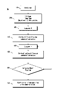
FIG. 1 is a schematic flow chart of a method of constructing below-grade
structures
according to a first example embodiment of the present invention, showing
steps for
carrying out the method.
FIGS. 2A-2E are schematic illustrations of a step portion of the method of
FIG. 1,
showing the installation of vertical structural steel beams/soldier piles in
the earth.
FIGS. 3A-3B are schematic illustrations of a step portion of the method of
FIG. 1,
showing the excavation of earth for an initial lift.
Date Recue/Date Received 2022-03-25
Doc. No. 328-6 CA
FIG. 4 shows and ZCWS-1 under-feather edge after troweling.
FIG. 5 is a cross section showing a feather joint created by applying high
strength
waterproof shotcrete over a first region and wherein the feathered region is
covered by a
second application of shotcrete over an adjacent region which spans and covers
the feather
joint of the first region.
FIG. 6 is a drawing showing the tabs welded to the structural steel beams.
FIG. 7 is a simplified diagram showing rebars coupled to tabs.
FIG. 8a is a simplified diagram showing locations of feather joints between
regions of
shotcrete in a first layer.
FIG. 8b is a simplified diagram showing locations of feather joints between
regions of
shotcrete in a second layer.
FIG. 8c shows the locations of the feather joints of the first layer relative
to the locations
of the feather joints in the second layer.
DETAILED DESCRIPTION OF EXAMPLE EMBODIMENTS
FIG. 1 shows a schematic, high-level flow chart depicting a method 10 of
constructing
below-grade structures according to a first example embodiment of the present
invention,
showing steps for carrying out the method. As shown therein, the first step
100 in the
process is to survey the site to lay out the position of the foundation walls
and steel
pilings. The next step 200 is the installation of the steel pilings. Holes are
drilled and the
steel piles are each placed within a hole. Support piles ranging in size from
W12 to W24
may be used and are placed in holes having a diameter of 0.75m to 1.2m
respectively. The
space between the pile and the hole wall is then backfilled with concrete
having a
compressive strength of at least 2 megapascals (MPa) and preferably 6 MPa to
10 MPa.
11
Date Recue/Date Received 2022-03-25
Doc. No. 328-6 CA
Reinforcing the piles in this manner obviates or lessens any twisting of the
piles that
would likely otherwise occur. Eliminating twisting is critical so that the
final wall is
crackless and waterproof and can stand up to forces over time.
This is followed by step 300, the excavation of a first "lift"; a vertical
excavation of some
1.2-2.5 m (4-8 feet), typically 1.5-1.8 m (5-6 feet) extending laterally as
far as needed.
Due to the sheer size of these walls on large projects, and the amount of
shotcrete that can
be applied in a single day, each lift or level is comprised of multiple side-
by-side regions
that are constructed and knitted together in a particular fashion over days of
applying
shotcrete. In step 400 a first level of the crackless waterproof wall is
constructed. The temi
"crackless" used hereafter is to mean a wall with zero or no cracks visible to
the human
eye or cracks that water leaks from referred to in this document as zero crack
waterproof
shotcrete (ZCWS). Drain board 4 is positioned in place between the steel
pilings and tabs
62a and angled tab 62b shown in FIG. 6 are welded to the steel pilings 64;
rebar (shown
generally at 702 in FIG. 7) is wire tied to the welded tabs 62b. The welding
of the tabs is
done as the piles 64 at each lift are exposed through excavation. Holes are
drilled into the
soil and ties or rods 5 having anchor heads 3 are installed into special tabs
(i.e., angled
tabs 62b) welded to the steel pilings 64 to secure the steel pilings 64, rebar
and drain
board 4 to the ground behind.
Referring once again to step 200, the vertical structural elements in the foim
of steel piles
are installed. These piles can consist of steel piles in the form of H-piles,
wide flange
sections or pipes or concrete piles.
As shown in the example depicted in FIGS. 2A-2E, the piles 101-105 are
installed at
regular intervals around the perimeter of the planned excavation prior to
commencement
of the excavation. The face of pile is set back from the planned face of wall
location by
the design thickness of the concrete facing and waterproofing. The steel piles
are installed
to a depth below the planned bottom of excavation as deteimined by the
structural design
of the excavation support system.
12
Date Recue/Date Received 2022-03-25
Doc. No. 328-6 CA
Once the H-pile locations have been laid out by a registered land surveyor,
the pilot hole
is drilled to the design bottom of pile elevation (see FIGS. 2A-2B). The H-
pile section is
then lowered into the pilot hole plumb (vertical) and back filled with
concrete having a
compressive strength of preferably 6-10 MPa. See FIGS. 2C-2D. This step is
repeated
until all of the H-pile sections are installed (FIG. 2E).
Referring now to Step 300 after installation of the H piles, the general
excavation
commences. The excavation is typically made in 1.5 m (5-foot) deep lifts, but
this may
vary depending on the soil type and construction requirements. See FIGS. 3A-
3B. The
depth of the lift 110 is indicated generally as L. The general idea behind
using 1.5 m (5-
foot) lifts is to make an excavation that allows for easy work by the
construction workers
without requiring ladders, scaffolding, etc., and which generally avoids the
need to
temporarily shore up the earth face where the workers are working. In this
regard, note
that if the excavation were 9 m (thirty feet deep), substantial shoring would
be required in
order to protect the workers from the substantial hazard of such a high
unsupported earth
face. Moreover, to work at the top of a 9 m (thirty-foot) excavation would
require very
long ladders and/or high scaffolding. The present invention avoids these
problems by
breaking the excavation down into sections scaled to the general working range
of a
human worker and scaled to minimize or avoid the need for temporary shoring.
In this
regard, the 1.5 m (five foot) depth of the excavation lift is not inflexible.
Indeed,
excavation lifts from less than a meter (a few feet) to perhaps as much as 2.4
m (eight
feet) work well. The more preferred range is between about 1.2 and 1.8 m (four
and six
feet), with the most preferred excavation lift depth being about 1.5 m (five
feet).
The earth is excavated flush with the interior face of the steel piles to
create a first lift 110
(see FIG. 3B). The earth surface should be vertical and smooth to receive the
drainage
board. Loose soils may be present at the top of the excavation and the initial
lift may
require some additional preparation to obtain a vertical smooth surface.
13
Date Recue/Date Received 2022-03-25
Doc. No. 328-6 CA
Once the concrete back-fill surrounding the H-piles has had ample time to set
(at least 12
hours), the first excavation lift is made. This lift 110 is typically in the
range of about 1.2
to 1.8 m (4 to 6) feet, as previously described.
Once excavated, the soils can be removed some 5-10 cm (2-4 inches) behind the
face of
the pile 64 to create a cavity" within each bay (between two H-piles) to
accept drainage
board 4, as shown in the side sectional view of Fig. 6.
This first excavation, or horizontal section referred to hereafter as the
first lift, is often
comprised of a plurality of horizontal regions when the length of the first
lift or horizontal
section is for example greater than 45 m (150 feet). In some instances each
horizontal
region may be less than 45 m (150 feet). This sometimes depends on how much
shotcrete
can be applied in one application.
In this instance, each horizontal lift or section is made of sub-sections or
rectangular
regions which are knitted together in a novel manner through feathered joints
of applied
ZCWS shotcrete. Furthermore, each horizontal section is knitted in a similar
manner to an
adjacent horizontal section below, through feathered joints of applied ZCWS.
Each
rectangular region is founed by constructing a wall portion of drainboard 4, a
steel
meshwork of rebar (e.g., 702 as shown most clearly in FIG. 7) connected to the
structural
steel beams 64 overlaying the drainboard 4, ties or anchor spigots coupled to
the stable
vertical structural steel beams drilled into soil behind the drainboard; and
waterproof
shotcrete layers, including a first shotcrete layer 1 and a second shotcrete
layer 2, coating
the aforementioned wall components; the regions in each horizontal section
form a
patchwork of interconnected regions, interconnected by an overlapping meshwork
of rebar
and feathered joints so that the horizontally and vertically-adjacent sections
are tied
together in a similar manner to provide excellent structural integrity, as
well as effective
water-proofing.
Preferably a first layer of ZCWS, referred hereafter as ZCWS-1 is comprised of
300 to
400 kg of Portland cement per m3. The mix may contain Fly Ash with a preferred
range of
14
Date Recue/Date Received 2022-03-25
Doc. No. 328-6 CA
between 30 kg and 112.5 kg. Alternatively, the mix may contain slag with a
preferred
range of between 60 kg and 225 kg. The most preferable embodiment of the mix
will
contain between 6kg and a maximum of 40.5 kg two-part powder containing micro-
silica
powder. The preferred embodiment of the admixture shall also contain between 5
kg to a
maximum of 36 kg of light-burn calcine magnesia powder. The micro-silica in
the
preferred admix includes a particle specific surface area (SSA) between
20m2/gr and
200m2/gr with an average particle size of between 15nm and 40nm in order to
meet the
preferred admix.
The second applied layer of ZCWS (ZCWS-2) which covers the first layer of
shotcrete is
preferably comprised of 300 kg to 400 kg of Portland cement per m3 and may
contain
between 30 kg and 112.5 kg of fly ash. Alternatively, the mix may contain
between 60 kg
and 225 kg of slag. The preferred mix will contain between 1 kg and up to 6 kg
two-part
powder containing micro-silica powder. It is also preferable the admixture
shall also
contain between 5 kg to a maximum of 36 kg of light-burn calcine magnesia
powder. The
micro-silica should have a preferred particle specific surface area (SSA)
between 20m2/gr
and 200m2/gr. The particle sizes preferably have an average between 15nm and
40nm.
The mix shall contain between 3 kg to a maximum of 30 kg of micro-silica with
an
average specific surface area (SSA) of 20m2/gr. Our preferred embodiment of
the mix
shall contain from 0.09 kg to 0.45 kg of natural rheology modifier and mix
stabilizer
(Acti-Gel). The mix preferably contains a preferred range from 6 kg to 12.5 kg
of liquid
crystalline admixture (VelositTm CA 115) which will contain a choice of
melamine,
naphthalene and/or polycarboxylate as water reducers. This ZCWS-2 layer is
reinforced
with microfibres, preferably 3 kg to 4.5 kg per cubic meter of concrete.
The steel piles, drainboard, rebar and ties together foitn an integrated
overall skeletal
structure which is coated with a sprayed first layer of ZCWS liquid concrete,
preferably
so-called "shotcrete" ZCWS-1, sprayed from a hose over this foundation grid
work to
create a sprayed-in-situ concrete wall section, the outside face of which is
then smoothed
if desired. A second layer ZCWS-2 is applied over the outside face when the
first layer
cures. Due to the sheer size of a horizontal lift when building large
structures, this
Date Recue/Date Received 2022-03-25
Doc. No. 328-6 CA
application of each layer of shotcrete is done in sections or regions across a
lift; a region
may span 45 m (150 feet) or more depending on the rate at which shotcrete can
be
applied. Thus, when an entire lift is completed it is comprised of a plurality
of side-by-
side rectangular regions having a substantially same height but which may vary
in width.
One problem which may lead to leaking and breakdown of such a wall is a lack
of
integrity at joints or seams where two adjacent wall regions meet. Knitting
two sections
together presents particular challenges. Notwithstanding, we have discovered a
method,
wherein the integrity of the wall is not compromised and wherein very large
walls can be
constructed which can retain water and not crack.
Turning now to the chart below 4 lifts are depicted wherein regions, shown as
cells for the
purpose of explanation, each of approximately 45 m (150 feet) wide and
approximately
1.5 m (5 feet) in height are shown. Cell (1,1) represents the first region of
the first lift that
is constructed and sprayed with a first layer of high strength low shrinkage
(ZCWS)
shotcrete. Cell (1,2) represents the second region of the first lift that is
constructed and
sprayed with the first layer of ZCWS, followed by regions, (1,3) and (1,4).
After the first
lift regions (1,1) to (1,4) are completed, region (2,1) of lift 2 is
constructed and sprayed
with a first layer of ZCWS, after which regions (2,2), (2,3), and (2,4) are
constructed and
similarly sprayed. Then lift 3 is constructed followed by lift 4 in a similar
manner.
above ground above ground above ground above ground
lift 1 1,4 1,3 1,2 1,1
lift 2 2,4 2,3 2,2 2,1
lift 3 3,4 3,3 3,2 3,1
lift 4 4,4 4,3 4,2 4,1
Essentially this this is a patchwork of wall regions constructed into a single
contiguous
crackless waterproof wall where all vertical and horizontal edges of regions
are joined to
adjacent edges of regions with waterproof crackless joints. A key aspect of
the
construction is the manner in which these regions (1,1) to (4,4) are knitted
together both
horizontally and vertically.
16
Date Recue/Date Received 2022-03-25
Doc. No. 328-6 CA
Since each region has 4 sides; any sides of a region which meet a side of an
adjacent
region is feathered. The taper of a feather is preferably less than 35 degrees
and preferably
more than 19 degrees. Providing a gradual slope is desired to achieve strength
and an
adequate bond between an under-feathered edge and an over-feathered edge.
Referring
now to FIG. 4 a feathered edge is shown wherein the average thickness of the
applied first
layer of ZCWS 40a is shown to be 13 cm (5 inches) thick tapering to a
thickness of about
2.5 cm (1 inch). The feathered edge is smooth after a wood float has been
passed over the
feathered area.
After washing dirt off, troweling and smoothing the area, a spray-lock
compound for
example, a post nano-colloidal silica spray such as SCP-327, is applied to the
smooth
feathered area. After this step is complete, and 24 hours have passed since
the application
of the first layer of ZCWS, spraying of shotcrete begins on the second region
40b and the
first feather joint 42a is covered with an over-over feather or complementary
feather 42b
essentially removing any visual indication that there is a feather joint in
the wall. This is
shown in FIG. 5 where a complete feather joint is shown.
Preferably feather joints are founed in the same manner, however the order in
which
feather joints are formed is important. For example, the description above
delineates how
the first region 40a and second region 40b are founed serially, where the
feather 42a of
region 40a is completed before the spraying of shotcrete of the second region
40b begins.
This defines feather joint 42a as being an under-feather and feather joint 42b
as being an
over-feather covering feather joint 42a.
After the first lift is complete in step 500 excavation takes place and in
step 600 execution
of the next lift is executed in a similar manner to the first lift.
Referring once again to the chart above, region (1,1) is the first region
having shotcrete
applied to it. This region has at least two edges which are under-feathered;
the edge facing
not yet founed region (2,1) and the edge facing region (1,2). The purpose of
providing
17
Date Recue/Date Received 2022-03-25
Doc. No. 328-6 CA
these under-feather surfaces is to accept an over-feather from (2,1) and (1,2)
so that these
can be knitted together to be crackless and waterproof as described above.
Region (1,2) is
applied after (1,1) is cured and has an over feather covering the under-
feather of (1,1).
This is explained above with reference to under-feather 42a and over-feather
42b. This
provides a fully waterproof j oint between (1,1) and (1,2). Two other edges of
(1,2) which
are adjacent to other regions are under-feathered. Thus region (1,2) will have
one over
feather conjoining (1,1) and an under-feather conjoining (1,3) and an under-
feather
conjoining (2,2). (1,3) and (2,2) will have complementary over-feathers to
join with (1,2).
Moving downward to lift 2, region (2,1) is constructed. One edge overlaps the
under-
feather of (1,1) with an over-feather and the other two edges are under-
feathered to
receive an over-feather from another region. Region (2,2) has two over
feathered edges
and 2 under feathered edge 2. The over feathered edges cover under feathered
edges on
(1,2) and (2,1). This method of patterning provides a substantially crackles
and waterproof
wall. As lifts are completed a second layer of ZCWS-2 is applied over the
first layer so
that the entire wall has two layers of shotcrete coating.
In shotcrete construction, surface preparation between layers to provide full
bond is
important. Similar preparation should be considered when an under-feathered
joint is
being coated with an over-feather of shotcrete. ACT 506.2-13, "Specification
for
Shotcrete," specifically addresses this in the requirements of Sections
3.4.2.1 and 3.4.2.2
that: "3.4.2.1 When applying more than one layer of shotcrete, use a cutting
rod, brush
with a stiff bristle, or other suitable equipment to remove all loose
material, overspray,
laitance, or other material that may compromise the bond of the subsequent
layer of
shotcrete. Conduct removal immediately after shotcrete reaches initial set.
"3.4.2.2 Allow
shotcrete to stiffen sufficiently before applying subsequent layers. If
shotcrete has
hardened, clean the surface of all loose material, laitance, overspray, or
other material that
may compromise the bond of subsequent layers. Bring the surface to a saturated
surface-
dry (SSD) condition at the time of application of the next layer of
shotcrete." The
shotcrete specification is actually more stringent than ACT 318-11, Section
6.4, on
construction joints, because it requires removal of all potential bond-
breaking materials
18
Date Recue/Date Received 2022-03-25
Doc. No. 328-6 CA
immediately after initial set, as well as the cleaning and SSD conditions
provided for in
3.4.2.2.
When the second layer of ZCWS-2 is applied over the first layer, care should
be taken to
ensure that feather joints of the second layer do not line up and directly
cover feather
joints from the first layer. Preferably, first and second layer feather joints
should be
staggered. This feature is illustrated in FIGS. 8a-c. FIG. 8a depicts the
location of feather
joints (horizontal and vertical) in the first layer, FIG. 8b depicts the
location of feather
joints (horizontal and vertical) in the second layer, and FIG. 8c shows the
staggered
locations of the feather joints in the first and second layers. It is also
suggested that the
second layer of ZCWS-2 contains non-steel micro-fibers thereby lessening any
chance of
cracking.
It should be noted, that regions that have an adjacent upper lift and a lower
lift a region on
each side thereof are feathered to be seamlessly joined to each of the 4
neighboring wall
regions. For example, region (2,2) is adjacent regions (1,2) (2,1) (2,3) and
(3,2). (2,2) will
have an over feather joining (1,2) and (2,1) and will have an under-feather
covered by an
over-feather of (3,2) and (2,3). An edge that meets a cured under-feather will
be an over-
feather.
After the second layer of ZCWS-2 is applied it is cleaned and a waterproofing
compound
(802 in FIG. 4) is applied to it.
Referring back to the flowchart of FIG. 1 after step 600 and 700 are complete,
any flow of
water from the bottom of the wall is monitored in step 800. Monitoring can be
done in
various ways. A visual inspection may indicate that the flow is considerable
and that
action must be taken to stop the flow, or a flow meter can be used to
deteimine if the flow
exceeds an acceptable or predeteimined amount. A flow of water in any
particular bay
may be passed through a flow meter as it is collected, or it can be collected
in a basin and
measured over a duration of time to deteimine the flow rate per bay. For
example, if the
flow exceeds 1 litre per minute per excavation bay, action by way of applying
grout to the
19
Date Recue/Date Received 2022-03-25
Doc. No. 328-6 CA
soil behind the wall may be taken to stop the flow. In this instance, curtain
grouting the
bottom section of the wall is used to prevent water from flowing. This curtain
grouting
seals the soil behind the shotcrete wall and the flow of water is abated. In
some instances
it may be necessary to install a floor slab to carry water pressure that may
be present.
It is to be understood that this invention is not limited to the specific
devices, methods,
conditions, or parameters of the example embodiments described and/or shown
herein,
and that the teiminology used herein is for the purpose of describing
particular
embodiments by way of example only. Thus, the telminology is intended to be
broadly
construed and is not intended to be unnecessarily limiting of the claimed
invention. For
example, as used in the specification including the appended claims, the
singular fauns
"a," "an," and "the" include the plural, the temi "or" means "and/or," and
reference to a
particular numerical value includes at least that particular value, unless the
context clearly
dictates otherwise. In addition, any methods described herein are not intended
to be
limited to the sequence of steps described but can be carried out in other
sequences, unless
expressly stated otherwise herein.
While the claimed invention has been shown and described in example forms, it
will be
apparent to those skilled in the art that many modifications, additions, and
deletions can
be made therein without departing from the spirit and scope of the invention
as defined by
the following claims. For example, while the drawings and description show and
describe
the exemplar use of H-piles, other shapes of piles can be employed, as known
in the art.
Date Recue/Date Received 2022-03-25