Note: Descriptions are shown in the official language in which they were submitted.
1
TITLE OF THE INVENTION
SUSPENDED CEILING SYSTEM INCORPORATING KEY AND KEYHOLE
COMBINATIONS AND METHOD OF INSTALLING SAME
FIELD OF THE INVENTION
[0001] The present invention relates to the general field of suspended
ceilings,
and is more specifically concerned with a suspended ceiling system
incorporating
key and keyhole assemblies.
BACKGROUND
[0002] Suspended ceiling systems are used to provide an aesthetic ceiling
surface to a room. In some instances, suspended ceiling systems generally
comprise a set of components such as ceiling edge support members,
crossbeams and junction elements.
[0003] These support members, components and elements are typically
attachable or otherwise engageable to one another via compatibly shaped
attachment end portions so as to form a planar grid-like structure connected
laterally along wall surfaces and to overhanging support structures, or the
original
ceiling of the room. This grid-like structure typically extends in a common
plane
disposed in a parallelly spaced apart relationship relative to the original
ceiling of
the room.
[0004] Existing suspended ceiling systems have many disadvantages. For
example, the set of components provided to mount and assemble the suspended
CA 3101872 2020-12-03
2
ceiling system has a fixed aesthetic configuration that is generally preset at
the
factory for a given room dimension. Thus the end user is limited to the preset
configuration and its associated aesthetics.
[0005] Furthermore, the compatibly shaped attachment end portions between the
members, components and elements, are often rendered unusable if, for some
reasons, some elongated crossbeams or support members need to shortened due
to, for example, a miscalculation of the dimensions of the destination room,
or a
modification of the desired design. In other words, these systems leave no
margin
for on site error corrections or modification of the design.
[0006] Furthermore, these suspended ceiling systems generally require
experienced professionals specifically trained for installing the desired
brand or
model of system, which raises the overall cost of the suspended ceiling once
installed.
[0007] Thus, there is a need on the market for an improved suspended ceiling
system.
[0008] Against this background, there exists a need in the industry to provide
suspended ceiling system mitigating at least in part the above-noted
disadvantages of existing suspended ceiling system. An object of the present
invention is therefore to provide such suspended ceiling systems.
SUMMARY OF THE INVENTION
[0009] In a broad aspect, there is provided a suspended ceiling system for
CA 3101872 2020-12-03
3
suspending panels, comprising: a plurality of elongated beams each defining a
beam longitudinal axis, each of the beams defining longitudinally opposed beam
end sections; a plurality of connectors for connecting the beams to each other
to
form a panel support structure for supporting the panels, each of the
connectors
defining at least two spaced apart beam coupling sections for each coupling to
to a
respective one of the beams through one of the beam end sections; and a
plurality
of locking keys for selectively locking the connectors and beams to each
other;
wherein, with the suspended ceiling system assembled, the beams are joined to
each other by the connectors to form a grid configured for supporting the
panels,
the beams and connectors forming connector-to-beam junctions each including
one of the beam end sections and one of the beam coupling sections engaging
each other and together defining a keyhole, the keyhole including keyhole beam
and connector portions defined respectively by the one of the beam end and
coupling sections, the keyhole receiving thereinto one of the locking keys so
that
movements of the one of the beam end sections and the one of the beam coupling
sections relative to each other perpendicularly to the keyhole are prevented
to
secure the one of the beam end sections and the one of the beam coupling
sections to each other.
[0010] There may also be provided a suspended ceiling system wherein the
keyhole is elongated and extends substantially parallel to the beam
longitudinal
axis.
[0011] There may also be provided a suspended ceiling system wherein each
connector-to-beam junction is configured and sized to allow relative movements
between the beam end section and the beam coupling section perpendicularly to
the beam longitudinal axis when the locking key is removed from the keyhole.
CA 3101872 2020-12-03
4
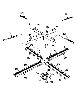
[0012] There may also be provided a suspended ceiling system wherein the
locking key is slidable toollessly in the keyhole.
[0013] There may also be provided a suspended ceiling system wherein the
locking key includes a substantially elongated key body of substantially
constant
transversal cross-sectional configuration therealong.
[0014] There may also be provided a suspended ceiling system wherein the
locking key further includes a handling portion extending from the key body
and
protruding laterally relative thereto.
[0015] There may also be provided a suspended ceiling system wherein the beam
coupling section defines a longitudinal coupling section groove extending
thereinto, the keyhole connector portion extending from the coupling section
groove laterally relative thereto into the beam coupling section; and the beam
end
section defines a protrusion inserted in the coupling section groove when the
beam coupling section and the beam end section are joined to each other, the
keyhole beam portion extending in the protrusion laterally relative thereto so
that
when the beam coupling section and the beam end section are joined to each
other, the keyhole beam and coupling portions face each other to together
define
the keyhole.
[0016] There may also be provided a suspended ceiling system wherein the
protrusion extends substantially along the entirety of the beam and wherein
opposed keyhole beam portions provided in each beam end section are joined to
each other through a keyhole groove so that the keyhole groove and keyhole
beam portions together defines a longitudinal groove of substantially constant
CA 3101872 2020-12-03
5
transversal cross-sectional configuration therealong extending along the
entirety of
the protrusion.
[0017] There may also be provided a suspended ceiling system wherein at least
some of the beams each define a pair of panel support flanges laterally
protruding
from the protrusion opposed to each other so that the at least some of the
beams
each have generally T-shaped cross-sectional configuration.
[0018] There may also be provided a suspended ceiling system further
comprising decorative elements supported in register with the connectors to
hide
the connectors, the decorative elements each defining a decorative element
keyhole portion positioned in prolongation of the keyhole beam portions so
that a
single locking key locks both one of the beams and the decorative element to
the
connector when the suspended ceiling system is assembled.
[0019] There may also be provided a suspended ceiling system wherein the
plurality of connectors includes T-shaped edge connectors having three edge
arms
each provided with a respective beam coupling section, L-shaped corner
connectors having two corner arms each provided with a respective beam
coupling
section and X-shaped middle connectors having four middle arms each provided
with a respective beam coupling section, wherein, when the suspended ceiling
system is assembled, the edge connector and corner connectors are provided at
a
periphery of the suspended ceiling system and the middle connectors are
provided
inside the periphery of the suspended ceiling system.
[0020] There may also be provided a suspended ceiling system further
comprising a plurality of mounting brackets mountable to a wall, each mounting
CA 3101872 2020-12-03
6
bracket including a wall mount mountable to a wall and a connector support
extending therefrom, the connector support being configured for supporting
thereonto the edge and corner connectors.
[0021] There may also be provided a suspended ceiling system wherein the
connector support includes a support top surface facing upwardly when the
connector support is operatively mounted to the wall and a connector
protrusion
protruding from the support top surface, and wherein the corner and edge
connectors each define a mounting groove extending therealong for receiving
the
connector protrusion when supported by the mounting bracket.
[0022] There may also be provided a suspended ceiling system further
comprising a guide tool including a body configured for engaging the mounting
brackets and a wire extending therefrom for indicating an horizontal direction
along
which the system is to be assembled.
[0023] There may also be provided a suspended ceiling system wherein at least
some of the middle connectors are provided with a support extending upwardly
therefrom or securing the at least some of the middle connectors to an
overhanging structure.
[0024] There may also be provided a suspended ceiling system wherein the
plurality of connectors includes edge connectors having four edge connector
arms
each provided with a respective beam coupling section, two of the edge
connector
arms being colinear, with remaining connector arms forming a V-shape and
extending from the two of the edge connector arms, corner connectors having
three corner arms each provided with a respective beam coupling section, two
of
CA 3101872 2020-12-03
7
the corner arms being perpendicular to each other and being bisected by a
remaining arm and X-shaped middle connectors having four middle arms each
provided with a respective beam coupling section, wherein, when the suspended
ceiling system is assembled, the edge connector and corner connectors are
provided at a periphery of the suspended ceiling system and the middle
connectors are provided inside the periphery of the suspended ceiling system.
[0025] There may also be provided a suspended ceiling system wherein the
connectors and beams are all made of wood.
[0026] There may also be provided a suspended ceiling system comprising the
suspended ceiling system according to claim 1 in an assembled configuration in
which the grid is defined, and panels supported by the suspension system to
fill
empty spaces defined by the grid.
[0027] Advantageously, the proposed suspended ceiling can be relatively easily
mounted, and eventually as easily disassembled if desired, mostly toollessly,
using
only a relatively small number steps in which only of the most basic carpenter
tools
such as a hammer, nails, a hand saw and a level tool are needed.
[0028] Further advantageously, the customizable suspended ceiling system
allows a user to relatively easily customize the latter between a relatively
simple
ornamental moulding pattern, and a highly complex design pattern visible along
the surface of the suspended ceiling system using a relatively small basic set
of
modular components thereof.
[0029] Other objects, advantages and features of the present invention will
CA 3101872 2020-12-03
8
become more apparent upon reading of the following non-restrictive description
of
some embodiments thereof, given by way of example only with reference to the
accompanying drawings.
BRIEF DESCRIPTION OF THE DRAWINGS
[0030] FIGURE 1, in a perspective view, illustrates an embodiment of a
suspended ceiling system, according to the present invention;
[0031] FIGURE 2, in an alternative perspective view, illustrate the suspended
ceiling system of FIG. 1;
[0032] FIGURE 3, in a perspective view, illustrates a connector part of the
suspended ceiling system of FIG. 1;
[0033] FIGURE 4, in an alternative perspective view, illustrates the connector
of
FIG. 3;
[0034] FIGURE 5, in top plan view, illustrates the connector of FIG. 3;
[0035] FIGURE 6, in a bottom plan view, illustrates the connector of FIG. 3;
[0036] FIGURE 7, in a side elevation view, illustrates the connector of FIG.
3;
[0037] FIGURE 8, in a perspective view, illustrates an other connector also
part of
the suspended ceiling system of FIG. 1;
CA 3101872 2020-12-03
9
[0038] FIGURE 9, in an alternative perspective view, illustrates the connector
of
FIG. 8;
[0039] FIGURE 10, in top plan view, illustrates the connector of FIG. 8;
[0040] FIGURE 11, in a bottom plan view, illustrates the connector of FIG. 8;
[0041] FIGURE 12, in a front elevation view, illustrates the connector of FIG.
8;
[0042] FIGURE 13, in a side elevation view, illustrates the connector of FIG.
8;
[0043] FIGURE 14, in a perspective view, illustrates yet an other connector
also
part of the suspended ceiling system of FIG. 1;
[0044] FIGURE 15, in an alternative perspective view, illustrates the
connector of
FIG. 14;
[0045] FIGURE 16, in top plan view, illustrates the connector of FIG. 14;
[0046] FIGURE 17, in a bottom plan view, illustrates the connector of FIG. 14;
[0047] FIGURE 18, in a front elevation view, illustrates the connector of FIG.
14;
[0048] FIGURE 19, in a first side elevation view, illustrates the connector of
FIG.
14;
CA 3101872 2020-12-03
10
[0049] FIGURE 20, in a rear elevation view, illustrates the connector of FIG.
14;
[0050] FIGURE 21, in a second side elevation view, illustrates the connector
of
FIG. 14;
[0051] FIGURE 22, in a perspective view, illustrates a mounting bracket part
of
the suspended ceiling system of FIG. 1;
[0052] FIGURE 23, in top plan view, illustrates the mounting bracket of FIG.
22;
[0053] FIGURE 24, in a front elevation view, illustrates the mounting bracket
of
FIG. 22;
[0054] FIGURE 25, in a rear elevation view, illustrates the mounting bracket
of
FIG. 22;
[0055] FIGURE 26, in a side elevational cross-sectional view, illustrates the
mounting bracket of FIG. 22 secured to a wall and engaged with the connector
of
FIG. 9, the latter being secured using a locking key to a beam, both part of
the
suspended ceiling system of FIG. 1;
[0056] FIGURE 27, in a top plan view, illustrates the beam of FIG. 26;
[0057] FIGURE 28, in a front end view, illustrates the beam of FIG. 26;
[0058] FIGURE 29, in a perspective view, illustrates the beam of FIG. 26;
CA 3101872 2020-12-03
11
[0059] FIGURE 30, in a perspective view, illustrates a decorative element part
of
the suspended ceiling system of FIG. 1;
[0060] FIGURE 31, in a front end view, illustrates the decorative element of
FIG.
30;
[0061] FIGURE 32, in an alternative perspective view, illustrates the
decorative
element of FIG. 30;
[0062] FIGURE 33, in a side elevation view, illustrates the decorative element
of
FIG. 30;
[0063] FIGURE 34, in a perspective view, illustrates a locking key part of the
suspended ceiling system of FIG. 1;
[0064] FIGURE 35, in an alternative perspective view, illustrates the locking
key
of FIG. 34;
[0065] FIGURE 36, in first side elevation view, illustrates the locking key of
FIG.
34;
[0066] FIGURE 37, in second side elevation view, illustrates the locking key
of
FIG. 34;
[0067] FIGURE 38, in a rear end view, illustrates the locking key of FIG. 34;
CA 3101872 2020-12-03
12
[0068] FIGURE 39, in a front end view, illustrates the locking key of FIG. 34;
[0069] FIGURE 40, in a perspective view, illustrate an alternative embodiment
of
the connector of FIG. 14;
[0070] FIGURE 41, in a perspective view, illustrate an alternative embodiment
of
the connector of FIG. 3;
[0071] FIGURE 42, in a perspective view, illustrate an alternative embodiment
of
the connector of FIG. 8;
[0072] FIGURE 43, in a perspective view, illustrate an alternative embodiment
of
the mounting bracket of FIG. 22;
[0073] FIGURE 44, in a perspective view, illustrate an alternative embodiment
of
the beam of FIG. 26;
[0074] FIGURE 45, in a perspective exploded view, illustrates assembly of
various components of the system of FIG. 1 to each other in which the
connector
of FIG. 8 is used;
[0075] FIGURE 46, in a perspective view, illustrates the components of FIG. 45
assembled to each other;
[0076] FIGURE 47, in a perspective exploded view, illustrates assembly of
various components of the system of FIG. 1 to each other in which the
connector
of FIG. 3 is used;
CA 3101872 2020-12-03
13
[0077] FIGURE 48, in a perspective view, illustrates the components of FIG. 47
assembled to each other;
[0078] FIGURE 49, in a perspective exploded view, illustrates assembly of
various components of the system of FIG. 1 to each other in which the
connector
of FIG. 14 is used;
[0079] FIGURE 50, in a perspective view, illustrates the components of FIG. 49
assembled to each other;
[0080] FIGURES 51, in a bottom plan view, illustrates a configuration of the
suspended ceiling system of FIG. 1 in which a first aesthetic aspect is
achieved;
[0081] FIGURES 52, in a bottom plan view, illustrates a configuration of the
suspended ceiling system of FIG. 1 in which a second aesthetic aspect is
achieved;
[0082] FIGURES 53, in a bottom plan view, illustrates a configuration of the
suspended ceiling system of FIG. 1 in which a third aesthetic aspect is
achieved;
[0083] FIGURES 54, in a bottom plan view, illustrates a configuration of the
suspended ceiling system of FIG. 1 in which a fourth aesthetic aspect is
achieved;
[0084] FIGURE 55, in a perspective view, illustrates a connector that is
usable as
an alternative to the connector of FIG. 14;
[0085] FIGURE 56, in a perspective view, illustrates a connector that is
usable as
CA 3101872 2020-12-03
14
an alternative to the connector of FIG. 8;
[0086] FIGURE 57, in a perspective view, illustrates another connector that is
usable as an alternative to the connector of FIG. 14;
[0087] FIGURE 58, in a bottom plan view, illustrates diamond-shaped
aesthetical
customization of the suspended ceiling system using the connectors of FIGS. 3,
55
and 56;
[0088] FIGURE 59, in a perspective view, illustrates an adjustable suspension
element part of some embodiments of the suspended ceiling system of FIG 1;
[0089] FIGURE 60, in a side elevational cut-away view, illustrates engagement
between the locking keys and keyholes formed by beams and connectors in which
the locking key secures one beam and one connector to each other;
[0090] FIGURE 61, in a perspective view, illustrates a pair grid-like
structures of
the suspended ceiling system of FIG. 1, here show mounted vertically in a self-
standing V-shaped configuration and used as a support for a marketing backdrop
at a trade show boot or the like; and
[0091] FIGURE 62, in a perspective view, illustrates a guide tool slidably
engaged
to mounting brackets and usable to selectively align components of the
suspended
ceiling system of FIG. 1 during its assembly.
CA 3101872 2020-12-03
15
DETAILED DESCRIPTION
[0092] The terms "substantially" and "about" are used throughout this document
to indicate variations in the thus qualified terms. These variations are
variations
that do not materially affect the manner in which the invention works and can
be
due, for example, to uncertainty in manufacturing processes or to small
deviations
from a nominal value or ideal shape that do not cause significant changes to
the
invention. Also, the present document describes the proposed system using
directional terminology with reference to a substantially horizontal ceiling
assembled using the proposed system. This terminology is for convenience
purposes and should not be used to restrict the scope of the appended claims
unless explicitly claimed.
[0093] FIGS. 1 and 2 collectively illustrate various aspects of an embodiment,
according to the present invention, of a suspended ceiling system 100,
hereinafter
"the system 100", usable for installation along a common plane, typically
extending
substantially parallelly adjacently the original ceiling or overhanging
support
structure 302 of a room, and laterally across the walls 304 thereof.
[0094] Referring to FIG. 2, the system 100 includes a plurality of elongated
beams
130. As seen in FIG. 27 for example, each beam 130 defines a beam longitudinal
axis 131 and longitudinally opposed beam end sections 132. Returning to FIG.
2,
the system 100 further includes a plurality of connectors 102, 103 and 124 for
connecting the beams 130 to each other to form a panel support structure for
supporting panels 162. Referring for example to FIG. 3, each of the connectors
124 defines at least two spaced apart beam coupling sections 127 for each
coupling to one of the beam end sections 132. For example, the connectors 102,
103 and 124 include respectively three, two and four beam coupling sections
127,
CA 3101872 2020-12-03
16
as seen for example respectively in FIGS. 8, 14 and 3.
[0095] A plurality of locking keys 146, seen for example in FIG. 34, are
provided
for for selectively locking the connectors 102, 103 and 124 and beams 130 to
each
other.
[0096] As seen in FIG. 2, when the system 100 is assembled, the beams 130 are
joined to each other by the connectors 102, 103 and 124 to form a grid
configured
for supporting the panels 162. Referring for example to FIG. 60, the beams 130
and connectors 102, 103 and 124 form connector-to-beam junctions 140 each
including one of the beam end sections 132 and one of the beam coupling
sections 127 engaging each other and together defining a keyhole 143, the
keyhole 143 including keyhole beam and connector portions 145 and 147 defined
respectively by the one of the beam end and coupling sections 132 and 127. The
keyhole 143 receives thereinto one of the locking keys 146 so that movements
of
the one of the beam end sections 132 and the one of the beam coupling sections
127 relative to each other perpendicularly to the keyhole 143 are prevented to
secure the one of the beam end sections 132 and the one of the beam coupling
sections 127 to each other.
[0097] Typically, the keyholes 143 are elongated and extend substantially
parallel
to the beam longitudinal axis 131. Each connector-to-beam junction 140 is
configured and sized to allow relative movements between the beam end section
132 and the beam coupling section 127 perpendicularly to the beam longitudinal
axis 131 when the locking key is 146 removed from the keyhole 143. Typically,
the
locking key 146 is slidable toollessly in the keyhole 143, but locking keys
146
requiring a hammer or other tool for such insertion are possible, for example
if fit
CA 3101872 2020-12-03
17
between the locking key 146 and keyhole 143 is very tight.
[0098] The connectors 102 and 103 are typically used at a periphery of the
system 100 when the latter is assembled, while the connectors 124 are used
inside the periphery of the system 100. The connectors 102 and 103 could be
directly secured to the walls 304 in some embodiments, for example using
screws,
nails, or an adhesive. However, in the embodiment of the system 100 shown in
the
drawings, mounting brackets 192, seen for example in FIG. 22, are secured to
the
walls 304, and the connectors 102 and 103 are then mounted thereto.
[0099] The system 100 includes a plurality of connectors 102, which are in
some
embodiments substantially T-shaped, and connectors 103, which are in some
embodiments substantially L-shaped. Each one of the connectors 103, seen for
example in FIG. 14, includes two arms 104. Each one of the connectors 103,
seen
for example in FIG. 8, includes three arms 104. As best illustrated in FIGS.
10, 11,
16 and 17, each arm 104 has a substantially elongated configuration and
defines a
proximal end 106 and a distal end 108, the beam end sections 127 being defined
at the latter. The arms 104 are joined to one another at their respective
proximal
ends 106 and each extend in the common plane of the system 100. The arms 104
may all have similar lengths or may be of different lengths.
[00100] As best illustrated in FIGS. 8, 9, 14 and 15, the connectors 102 and
103
define laterally oriented inner and outer longitudinal side surfaces 114 and
116
respectively, and, a pair of oppositely oriented upper side and underside
surfaces
118 and 120 extending parallelly relative to the common plane of the system
100.
[00101] The connectors 102 and 103 further defines a predetermined angle
CA 3101872 2020-12-03
18
between the longitudinal extension of the arms 104. In the connector 102, two
of
the arms 104 are colinear, and the third arm 104 extends perpendicularly
relative
thereto, typically in the common plane of the system 100. In the connector
103, the
two arms 104 are perpendicular to each other, forming angles of 90 or 270
degrees with each other at the inner longitudinal side surfaces 114, to fit
inside
and outside corners between two walls 304. It should be noted that for some
applications in which the walls 304 are note perpendicular to each other, the
two
arms 104 may be angled with any other suitable angle therebetween.
[00102] FIGS. 3 to 7 illustrate the connectors 124. Each one of the connectors
124 includes at least four arms 104. Each arm 104 has a substantially
elongated
configuration and defining a proximal end 106 and a distal end 108, the beam
coupling sections 127 being formed at the latter. The at least four arms 104
are
joined to one another at their respective proximal end 106 and extend away
from
each other in the common plane to form a cross-shaped configuration.
[00103] Thus, each one of the connectors 124 defines a pair of oppositely
oriented upper side and underside surfaces 118 and 120 extending parallelly
relative to the common plane of the system 100, and four corner edges 128
extending laterally inwardly between the arms 104 and parallelly relative to
the
common plane.
[00104] FIGS. 27, 28 and 29 inclusively, illustrate one of the beams 130. Each
one of the beams 130 has a substantially elongated configuration defining a
pair of
opposite beam end sections 132, an intermediate portion 134 extending
therebetween, and opposed upper side and underside longitudinal surfaces 136
and 138 extending parallelly relative to the common plane of the system 100.
CA 3101872 2020-12-03
19
[00105] Referring to FIGS. 46, 48 and 50, the system 100 typically defines a
plurality of connector-to-beam junctions 140 in corresponding number to the
number of arms 104 in the system 100, although leaving some of the arms 104
unsecured to a beam 130 is within the scope of the invention. As illustrated
in
FIGS. 7, 11, 12, 13, 17, 20 and 21, each one of the connector-to-beam
junctions
140 includes a longitudinal coupling section groove 142 extending at least
partially
longitudinally inwardly from each arm distal end 108 and into the beam
coupling
section 127, in the underside surface 120 of the respective arm 104. As
illustrated
in FIGS. 27 to 29, each one of the connector-to-beam junction 140 further
includes
a protrusion 144 extending at least along an upper side longitudinal portion
of each
opposed beam end portions 132 of each beam 130.
[00106] Referring now more particularly to FIGS. 34 to 39, each one of the
connector-to-beam junction 140 further includes the locking key 146. The
locking
key 146 has a substantially elongated configuration defining a substantially
elongated key body 148 of substantially constant transversal cross-sectional
configuration therealong, and an optional handling portion 150 at one end
thereof
and extending from the key body 148 and protruding laterally relative thereto.
[00107] Referring now more particularly to FIG. 60, the coupling section
groove
142 is shaped and sized for longitudinally receiving in a snug fit relation at
least a
longitudinally extending portion of a respective one of the protrusions 144 of
the
beam 130, such that the upper side longitudinal surface 136 thereof is
proximally
parallelly facing the underside longitudinal surface portion of the respective
arm
104.
[00108] The coupling section groove 142 and the protrusion 144 cooperatively
CA 3101872 2020-12-03
20
define a pair of oppositely facing surfaces 154 extending substantially
perpendicularly relative to the upper side longitudinal surface 136 of the
beam 130.
The keyhole connector portion 147 extends from the coupling section groove 142
laterally relative thereto into the beam coupling section 127, or in other
words in
the surface 154 of the connector 102, 103 or 124. Similarly, the keyhole beam
portion 145 extends in the protrusion 144 laterally relative thereto, into the
surface
154 of the protrusion 144, so that when the beam coupling section 127 and the
beam end section 132 are joined to each other, the keyhole beam and connector
portions 145 and 147 face each other to together define the keyhole 143.
[00109] The keyhole 143 is shaped and sized for slidably longitudinally
receiving
therein in a snug fit relation the body 148 of the locking key 146, so as to
transversally lock the respective beam end portion 132 of the beam 130 with
the
respective arm 104, as best illustrated in FIGS. 26 and 60.
[00110] Referring to FIGS. 1, 2, and 45 to 50 inclusively, a method of
installing
the customizable suspended ceiling system 100 of the present invention will
now
be described. In a first step, the plurality of connectors 102 and 103 have
their
respective outer longitudinal side surface 116 engaged in a suitably spaced
apart
relationship along the flat wall surfaces 304 and wall corners 310 of the
room. In a
second step, a suitable number of beams 130 and connectors 124 may be
successively assembled to form a substantially regular grid-like structure
extending between the plurality of connectors 102 and 103 by lockingly
engaging
the connector-to-beam junctions 140 therebetween using locking keys 146, as
illustrated in FIGS. 45 to 50 inclusively, the end result being the assembled
suspended ceiling system 100 as illustrated in FIGS. 1 and 2. As it will be
made
apparent from the description hereinafter, optional steps may be added to the
method described above with regards to additional elements that can be added
to
CA 3101872 2020-12-03
21
the invention such as drop-in panels 162, adjustable support components 272
and
wall mount arrangements 190.
[00111] Referring to FIGS. 2, 29, 46, 48 and 50, in some embodiments of the
system 100 according to the present invention, the beams 130 forming the
opening edges 165 in the grid-like structure each have their respective upper
side
surface 136 extending at least slightly laterally away from their respective
protrusion 144, and inwardly relative to the opening of the grid-like
structure, so as
to form a panel support flanges 164 extending longitudinally therealong. The
beams connected to the connectors 124 each define a pair of laterally
protruding
panel support flanges 164 from the protrusion 144, opposed to each other, so
that
the beams 130 connected to the connectors 124 each have generally T-shaped
cross-sectional configuration. In some embodiments, even the beams used at the
periphery of the system 100 have this T-shaped configuration, for example if
mounting brackets 192, described below, are used.
[00112] The system 100 is typically used in combination with a sufficient
number
of suitably sized and shaped drop-in panels 162 for closing each opening of
the
grid-like structure with the edges of the panels 162 resting on the panel
support
flanges 164, so as to cooperatively form with the grid-like structure a
ceiling
surface.
[00113] Referring to FIGS. 1, 30 to 33 and 51 to 53, in some embodiments of
the
system 100, the system 100 further comprises a plurality of decorative
elements
166 that are user selectively attachable to connectors 102, 103 and 124. Each
decorative element 166 includes a plate member 168 defining an upper side
surface 170, an underside surface 172 and a contour edge 174. Furthermore,
CA 3101872 2020-12-03
22
each decorative element 166 further includes two or more of the protrusions
144
located along the upper side surface 170 thereof, and in register for
engagement
with a respective connector groove 142 along the underside surface 172 of user
selected connectors 102, 103 and 124.
[00114] Furthermore, each decorative element 166 has a dimension in the
common plane of the system 100 that is at least sufficiently smaller than the
respective connector 102, 103 or 124 is attached, so as to allow beams 130 to
be
attached to a respective arm 104 thereof via the connector-to-beam junction
140.
In some embodiments, the decorative elements 166 are configured to be
supported in register with the connectors 102, 103 and 124 to hide the
connectors
102, 103 and 124, and define a keyhole decorative element portion 149, similar
to
the keyhole beam portion 145, and positioned in prolongation of the keyhole
beam
portions 145, so that a single locking key 146 locks both one of the beams 130
and
the decorative element 166 to the connector 102, 103 and 124 when the
suspended ceiling system 100 is assembled
[00115] As best illustrated in FIGS. 27 and 29, in some embodiments of the
system 100, the protrusion 144 extend longitudinally along the whole length of
the
beam 130, and opposed keyhole beam portions 145 provided in each beam end
section 132 are joined to each other through keyhole decorative element
portion
149 so that the keyhole decorative element portion 149 and keyhole beam
portions
145 together define a longitudinal groove of substantially constant
transversal
cross-sectional configuration therealong extending along the entirety of the
protrusion 144.
[00116] Thus, advantageously, the system 100 may be provided with a sufficient
CA 3101872 2020-12-03
23
number of beams 130 having each a same overall length that is equal to or
greater
than the greatest distance between two components of the system 100 so as to
allow a user to cut selected beams 130 to any desired length within that
overall
length of each beam 130.
[00117] As best illustrated in FIGS. 6, 7, 11 and 13, in some embodiments of
the
system 100, the grooves 142 all extend along the whole arms 104, so that
selected beams 130 may extend longitudinally across selected connectors 102,
103 and 124 and decorative elements 166.
[00118] Advantageously, the protrusion 144, the groove 142 and their
respective
recesses forming the keyholes 143 thus extending the whole length of,
respectively, the beams 130 and arms 104 , the beams 130 and, up to a certain
extent, the arms 104 themselves may be selectively cut to desired lengths so
as to
suit a particular application of the system 100. This aspect is an advantage
over
other known suspended ceiling system of the prior art, which generally do not
allow this on site customization of lengths of the components due to the end
connection arrangements of the latter's.
[00119] Referring to FIG. 56, in some embodiments, each connector 102 is
replaced by an alternative connector 102' including two arms 104 extending at
180
degrees opposed to each other, and two intermediate arms 122 having their
respective proximal end 106 joined centrally along the inner longitudinal side
surface 114 of the connector 102, at a junction of the two arms 104,
perpendicularly with each other.
[00120] Furthermore, each connector 103 is replaced by a connector 103' having
CA 3101872 2020-12-03
24
two arms 104 perpendicular to each other, and an intermediate arm 122
extending
from a junction of the two arms 104 and bisecting these two arms 104. As seen
in
FIG. 55, the intermediate arm may be inside a corner defined by the two arms
104,
or, as in the connector 103" shown in FIG. 57, may be outside of this corner.
Thus,
using the connectors 102, 103', 103" (if required) and 124, the assembled
system
100 may define a diamond grid-like structure relative to the parallelly
extending
walls 304 of a square room.
[00121] Referring to FIGS. 1, 47, 48, 59 and 60, in some embodiments of the
system 100, the system 100 further comprises an intermediate support 270
having
an elongated configuration defining a lower end connected to a substantially
centrally located upper side surface portion of user selected cross junction
components 124, and an upper end connected to a stationary support structure
312 overlying the common plane of the system 100. Thus, the system 100 may be
assembled to cover a substantially large common plane between widely spaced
apart walls 304 of a room without bowing down due to the overall weight of the
assembly.
[00122] Referring to FIG. 59, in some embodiments of the system 100, the
system 100 further comprises an adjustable support component 272 for
adjustably
connecting the upper end of the intermediate support 270 between two spaced
apart support structure members of the stationary support structure 312
overlaying
the common plane of the system 100.
[00123] The adjustable support component 272 includes a pair of support
brackets 274. Each support bracket 274 is connected to a respective one of the
spaced apart support structure members and includes a slot 176 extending
parallel
CA 3101872 2020-12-03
25
to the common plane of the system 100 and is oppositely parallelly facing the
slot
176 of the other support bracket 174 in the pair.
[00124] The adjustable support component 272 further includes an elongated
member 178 having a pair of oppositely extending end portions 180 and an
intermediate portion 182 extending therebetween. The elongated member 178 is
suitably sized and shaped so as to have the end portions 180 thereof slidably
engaged in a respective one of the oppositely facing slots 176 of the pair of
support brackets 274. The adjustable support component 272 further includes a
tubular member 184 slidably coaxially engaged along the intermediate portion
182
of the elongated member 178.
[00125] Thus, the intermediate support 270 may have its upper end adjustably
connected to the overlaying stationary support structure 312 through the
adjustable support component 272 having its pair of support brackets 274
connected between a pair of spaced apart support members of the stationary
support structure 312.
[00126] Referring to FIGS. 13, 22 to 26, 46 and 50, in some embodiments of the
system 100, the system 100 further comprises a wall mount arrangement 190 for
removably engaging the connectors 102 with the flat wall surfaces 304 and wall
corners 310 of the room.
[00127] The wall mount arrangement 190 includes a plurality of mounting
brackets 192. Each mounting bracket 192 has a substantially elongated
configuration defining a pair of spaced apart mounting bracket end portions
194
and a mounting bracket intermediate portion 196 extending therebetween.
CA 3101872 2020-12-03
26
[00128] Each mounting bracket 192 further defines front and rear longitudinal
side
surfaces 198 and 200 extending substantially the whole length thereof. The
rear
longitudinal surface 200 is adapted for longitudinal attachment in an end to
end
configuration along the walls and corners surfaces of the room and
substantially in
register with the common plane of the system 100 so as to surround the room
along the flat walls 304 and wall corners 310 thereof.
[00129] Each mounting bracket 192 further defines a lip 202 extending
longitudinally and substantially upwardly from the front longitudinal surface
198,
and in a parallelly spaced apart relationship relative to the rear
longitudinal surface
200 respectively, protruding from a top surface 197 of the mounting bracket
192.
The portion of the mounting bracket 192 below the lip 202 is configured for
mounting to the wall 304. The lip 202 and top surface 197 are configured for
supporting the connectors 102 and 103. To that effect, referring more
particularly
to FIGS. 8, 9, 20, 21 and 26, the wall mount arrangement 190 further includes
a lip
engaging recess 204 extending longitudinally and at least partially upwardly
inwardly relative to the underside surface 120 of each connector 102 and 103,
and
parallelly proximally the longitudinal outer side surface 116 thereof. The lip
engaging recess 204 is shaped and sized for removably engaging, in a snug fit
relation, the lip 202 of the mounting bracket 192 such that the longitudinal
underside surface 120 of the connector 102 is located substantially in
register with
a longitudinal underside edge 206 of the mounting bracket 192, as best
illustrated
in FIG. 26.
[00130] Thus, the plurality of mounting brackets 192 may be first relatively
easily
attached linearly in register with the common plane of the system 100 along
the
wall and corner surfaces of the room using nails and a hammer, or a nail
stapler,
followed with engaging the plurality of connectors 102 at user selected
positions
CA 3101872 2020-12-03
27
along the lip 202 of the mounting brackets 192.
[00131] Referring to FIG. 62, in some embodiments of the system 100, the
system 100 further comprises one or more guide tools 210.
[00132] The one or more guide tools 210 each include a first arm 110 and a
second arm 112 joined to one another through their respective proximal end
106,
with each arm extending distally therefrom in the common plane of the system
100
and at a predetermined angle relative to one another with respect to an outer
longitudinal side surface 116 of the guide tool 210 extending along both the
first
and second arms 110 and 112 respectively.
[00133] The predetermined angle for the guide tool 210 being one of 180
degree,
positive 90 degree, or negative 90 degree, depending on the location of
engagement of the guide tool 210 along the plurality of mounting brackets 192
attached to the walls 304 (e.g. a flat wall surface, a negative wall corner or
a
positive wall corner respectively).
[00134] Furthermore, the guide tool 210 defines a longitudinal underside
surface
120 extending along the longitudinal underside of both the first and second
arms
110 and 112, and a lip engaging recess 204 extending there along and
proximally
parallelly the longitudinal underside surface 120 of the guide tool 210.
[00135] Thus, the one or more guide tools 210 are usable, in cooperation with
mounting brackets 192 attached along selected wall surfaces 304 of the room, a
cord 212 removably attached to a centered portion of the guide tool 210
through a
hand knob 214, or the like, and a common level tool, for assisting a user to
CA 3101872 2020-12-03
28
relatively easily align the attachment of the plurality of mounting brackets
192
along all the walls of the room in a true horizontal common plane.
[00136] The guide tool 210 may further be useful for assisting a user to
rectilinearly align alternating longitudinal assemblies of beams 130 and
connectors
124 extending between two connectors 102 or 103 mounted along oppositely
facing walls 304, two adjacent walls 304, or wall corners 310 of the room.
[00137] The various structural components of the suspended ceiling system 100
may be sized to substantially any reasonable scale for a given application.
For
example, and non-limitingly, typical dimensions for the connector 102 may
measure about 6" by 6" in the common plane, and about 1.25" in height, while
the
connector 124 may measure about 15.5" in the common plane and 1.25" in height.
The typical dimensions of the other structural components such as the beams
130
and drop-in panels 162 may vary quite substantially, depending on the desired
size and proportions of the aesthetical aspect of the resulting grid-like
structure
visible by a person standing in the room.
[00138] The various components of the suspended ceiling system 100 can be
made of any suitably rigid material or combination of materials such as, for
example, wood, a suitably rigid plastic using an appropriate injection or
extrusion
manufacturing process, and metal sheets using any known punch press process.
[00139] In some embodiments, at least the various structural components may be
entirely made of wood. Advantageously, as illustrated in FIGS. 40 to 44, all
the
structural components of the customizable suspended ceiling system 100, such
as
the connectors 102, 103 and 124 beams 130, connector-to-beam junctions 140
CA 3101872 2020-12-03
29
and wall mount arrangements 190, including the locking key 146, may be
entirely
made out of an assembly of recycled woodwork leftovers having a same
thickness.
For example, as exemplified in the figures, 0.292" thick wooden sticks, or
baguettes, may be stacked side-by-side using glue, wood staples or the likes.
Thus a large part of the system 100 may be economically manufactured, as well
as representing an environmentally conscious product.
[00140] Further advantageously, the suspended ceiling system 100 of the
present
invention, as described above, can be easily mounted, and eventually as easily
disassembled if desired, using only a relatively small number of the most
basic
carpenter tools such as a hammer, nails, a hand saw and a level tool. Of
course,
gains in assembly time may be achieved using a power nail stapler, a power
miter
saw and a small laser level tool.
[00141] Further advantageously, in some embodiments, the customizable
suspended ceiling system 100 of the present invention may be assembled by a
user having little or no experience in the assembly of suspended ceilings.
Indeed,
the use of locking keys 146 for assembling the grid-like structure means that,
advantageously, over 90% of the assembly work of the system 100 does not need
tools at all.
[00142] Further advantageously, the customizable suspended ceiling system 100
allows a user to relatively easily customize the latter between a relatively
simple
ornamental molding pattern, and a highly complex design pattern visible along
the
surface of the suspended ceiling system 100 using a relatively small basic set
of
modular components thereof.
CA 3101872 2020-12-03
30
[00143] Further advantageously, the high modularity of the suspended ceiling
system 100 allows a user to modify the design pattern as the suspended ceiling
is
progressively assembled such as, for example, across two large sections of a
same room.
[00144] Further advantageously, a set of ready to install components for
mounting
and assembling the customizable suspended ceiling system 100 in a room of a
given size may be all packaged in a single box having sides no greater than
the
area of one of the drop-in panels of the system, since the drop-in panels have
the
greatest dimension of the components. Thus, the customizable suspended ceiling
system 100 may be advantageously sold on-line and delivered via parcel
shipping
to customers.
[00145] Further advantageously, as illustrated in FIG. 61, an assembled grid-
like
structure of the system 100, but without wall mount arrangements 190, may be
used as a collapsible and easily portable temporary wall partition. In the
figure, two
such grid-like structures of the system 100 are disposed vertically and joined
to
one another along adjacent vertical side edges thereof in a self-standing V-
shaped
configuration that can be used as a backdrop structure for supporting
marketing
canvas behind a trade show boot or the like.
[00146] Although there is illustrated in the figures mainly square-shaped
decorative elements 166, as in FIGS. 1, 30, 32 and 58, it is to be understood
that
all or selected decorative elements 166 of the system 100 may have other shape
configurations such as, non !imitatively, rounded, rectangular, hexagonal, as
exemplified in FIG. 53, octagonal, and the likes. Or the user may chose to
have a
system 100 without any decorative elements 166 at all, as exemplified in FIG.
54.
CA 3101872 2020-12-03
31
[00147] Although the present invention has been described hereinabove by way
of exemplary embodiments thereof, it will be readily appreciated that many
modifications are possible in the exemplary embodiments without materially
departing from the novel teachings and advantages of this invention.
Accordingly,
the scope of the claims should not be limited by the exemplary embodiments,
but
should be given the broadest interpretation consistent with the description as
a
whole.
CA 3101872 2020-12-03