Note: Descriptions are shown in the official language in which they were submitted.
CA 03102964 2020-12-07
WO 2019/239397
PCT/IL2019/050543
TOOL HOLDER HAVING INTEGRALLY FORMED ANTI-VIBRATION COMPONENT
AND CUTTING TOOL PROVIDED WITH TOOL HOLDER
FIELD OF THE INVENTION
The subject matter of the present application relates to tool holders, in
general, and to
such tool holders having an anti-vibration component, in particular, and to
such an anti-vibration
component being manufactured by additive manufacturing further in particular.
BACKGROUND OF THE INVENTION
Tool holders can be provided with an anti-vibration arrangement for
suppressing
vibration of the tool holder during metal cutting operations. Typically, the
anti-vibration
arrangement is a spring-mass system that includes a cavity and a vibration
absorbing mass
suspended therein by elastic supporting members. The cavity can be filled with
a viscous fluid.
In some such anti-vibration arrangement said elastic supporting members can be
formed
from o-ring type structures. Examples of such tool holding systems, are
disclosed in, for
example, US 9,579,730, US 2016/305503, US 7,234,379, US 6,443,673 and US
3,774,730.
By virtue of additive manufacturing, alternative anti-vibration arrangements
can be used.
For example, WO 2012/084688 discloses cavities that are filled with a flowable
mixture of
materials such as powder and gas or liquid and gas. A spatial structure is
provided in said
cavities as a three-dimensional flow obstacle. Another example, US 8,946,585,
discloses a
cavity provided for dampening tool vibration that is at least partially filled
with non-solidified
(non-melted) powderous material.
It is an object of the subject matter of the present application to provide a
new and
improved anti-vibration arrangement.
SUMMARY OF THE INVENTION
In accordance with a first aspect of the subject matter of the present
application there is
provided a tool holder, elongated along a holder longitudinal axis thereof and
having a tool anti-
vibration component, the tool anti-vibration component comprising:
a component housing portion; and
- 1 -
CA 03102964 2020-12-07
WO 2019/239397
PCT/IL2019/050543
an anti-vibration arrangement comprising:
an interior component cavity formed in component housing portion and having
inwardly facing cavity wall surface;
a vibration absorber portion disposed within the component cavity and
integrally
formed with the component housing portion to have unitary one-piece
construction
therewith, the vibration absorber portion comprising:
a vibration absorbing mass suspended within the component cavity; and
at least one resilient suspension member connecting the vibration
absorbing mass to the component housing portion; and
an oscillating space located between the vibration absorber portion and the
inwardly facing cavity wall surface, wherein:
the vibration absorbing mass is configured to oscillate within the
oscillating space upon elastic deformation of the at least one suspension
member.
In accordance with a second aspect of the subject matter of the present
application there
is provided a cutting tool comprising:
a tool holder of the type described above; and
a cutting portion comprising at least one cutting insert.
In accordance with a third aspect of the subject matter of the present
application there is
provided a tool holder, elongated along a holder longitudinal axis thereof and
having a tool anti-
vibration component, the tool anti-vibration component comprising:
a component housing portion; and
an anti-vibration arrangement comprising:
an interior component cavity formed in component housing portion and having
inwardly facing cavity wall surface;
a vibration absorber portion disposed within the component cavity and
integrally
formed with the component housing portion to have unitary one-piece
construction
therewith, the vibration absorber portion comprising:
a vibration absorbing mass suspended within the component cavity; and
at least one resilient suspension member connecting the vibration
absorbing mass to the component housing portion; and
- 2 -
CA 03102964 2020-12-07
WO 2019/239397
PCT/IL2019/050543
an oscillating space located between the vibration absorber portion and the
inwardly facing cavity wall surface, wherein:
the oscillating space is filled with a viscous fluid; and
the vibration absorbing mass is connected to the component housing
portion only at the at least one suspension member.
It is understood that the above-said is a summary, and that features described
hereinafter
may be applicable in any combination to the subject matter of the present
application, for
example, any of the following features may be applicable to the tool holder or
the cutting tool:
The elastic deformation can be caused by a tensile load applied by the
vibration
absorbing mass on the at least one suspension member.
The component housing portion can comprise a first additively manufactured
metallic
material. The vibration absorbing mass can comprise a second additively
manufactured metallic
material. The first and second additively manufactured metallic materials can
be different from
one another.
The vibration absorber portion can comprise only a single resilient suspension
member
connecting the vibration absorbing mass to the component housing portion, such
that the
vibration absorbing mass is cantilevered within the component cavity.
The oscillating space can entirely circumferentially surround the vibration
absorber
portion.
The oscillating space can be filled with a viscous fluid.
The vibration absorbing mass can be connected to the component housing portion
only at
the at least one suspension member.
The at least one suspension member may not be pre-loaded.
The at least one suspension member can be pre-loaded.
The anti-vibration arrangement can comprise a tuning member that protrudes
into the
oscillating space and that abuts one of the at least one suspension members so
that the suspension
member is pre-loaded.
The at least one suspension member can be elongated in the same direction as
the tool
holder.
- 3 -
CA 03102964 2020-12-07
WO 2019/239397
PCT/IL2019/050543
The at least one suspension member can comprise a suspension member peripheral
surface extending about a suspension member longitudinal axis. The suspension
member
peripheral surface can have a cylindrical shape.
The component cavity and the vibration absorbing mass can be elongated in the
same
.. direction as the at least one suspension member.
The at least one suspension member can be connected to a mass longitudinal end
of the
vibration absorbing mass.
The vibration absorber portion can comprise two suspension members connected
to two
opposite mass longitudinal ends of the vibration absorbing mass.
The vibration absorbing mass and the at least one suspension member can be co-
axial
with the tool holder.
The vibration absorbing mass can have a mass length measured in its lengthwise
direction. The at least one suspension member can have a suspension member
length measured
in its lengthwise direction. The mass length can be at least five times
greater than the suspension
member length.
The vibration absorbing mass can have a mass maximum cross-sectional
dimension. The
at least one suspension member can have a suspension member maximum cross-
sectional
dimension. The mass maximum cross-sectional dimension can be at least five
times greater than
the suspension member maximum cross-sectional dimension.
The vibration absorbing mass can have a mass length extending along a mass
longitudinal axis, and can comprise two opposite mass end surfaces (56) and a
mass peripheral
surface extending therebetween, the mass peripheral surface (58) extending
about the mass
longitudinal axis.
The vibration absorbing mass can have a mass transverse cross-section taken in
a plane
perpendicular to the mass longitudinal axis, which can be uniform for at least
60% of the mass
length.
The mass peripheral surface can have a cylindrical shape except at the mass
end surfaces.
The vibration absorbing mass can have a mass transverse cross-section taken in
a plane
perpendicular to the mass longitudinal axis that is non-uniform therealong.
The mass peripheral surface can taper inwardly towards the mass longitudinal
axis.
- 4 -
CA 03102964 2020-12-07
WO 2019/239397
PCT/IL2019/050543
The mass end surfaces can be planar and oriented perpendicular to the mass
longitudinal
axis.
The mass end surfaces can taper inwardly towards the mass longitudinal axis in
a
direction away from the mass peripheral surface.
The component cavity can have a shape that matches a shape of the vibration
absorbing
mass.
The tool anti-vibration component can be elongated, along a component
longitudinal axis
thereof, and in same direction as the tool holder.
The tool anti-vibration component can further comprise two opposite component
end
surfaces and a component peripheral surface extending therebetween, the
component peripheral
surface extending about the component longitudinal axis and at least one
component through
hole extending between, and opening out to, the cavity wall surface and one of
the component
end surfaces and the component peripheral surface. The component cavity can be
sealed by at
least one sealing member located in the at least one component through hole.
The tool anti-vibration component can comprise exactly two component through
holes.
The at least one component through hole can extend between, and opens out to,
the cavity
wall surface and one of the component end surfaces.
The cutting portion can be releasably attached to the tool holder.
The anti-vibration arrangement can be disposed at a forward end of the cutting
tool.
The at least one suspension member can be a spring extending helically about a
suspension member longitudinal axis.
The tool anti-vibration component can comprise an internal coolant channel
extending
internally through the at least one suspension member and the vibration
absorbing mass.
The cutting tool can be non-rotary.
BRIEF DESCRIPTION OF THE FIGURES
For a better understanding of the present application and to show how the same
may be
carried out in practice, reference will now be made to the accompanying
drawings, in which:
Fig. 1 is a perspective view of a cutting tool in accordance with a first
embodiment of the
present application, showing an anti-vibration component;
- 5 -
CA 03102964 2020-12-07
WO 2019/239397
PCT/IL2019/050543
Fig. 2 is a partial longitudinal cross-sectional view of the tool anti-
vibration component
in Fig. 1, showing an anti-vibration arrangement;
Fig. 3 is a first radial cross-sectional view of the tool anti-vibration
component taken
along line III-III in Fig. 2;
Fig. 4 is a second radial cross-sectional view of the tool anti-vibration
component taken
along line IV-IV in Fig. 2;
Fig. 5 is a detail of Fig. 2, indicated by reference numeral V;
Fig. 6 is a schematic view of a partial longitudinal cross-section of the tool
anti-vibration
component, in accordance with a second embodiment of the present application;
Fig. 7 is a schematic view of a partial longitudinal cross-section of the tool
anti-vibration
component, in accordance with a third embodiment of the present application;
Fig. 8 is a schematic view of a partial longitudinal cross-section of the tool
anti-vibration
component, in accordance with a fourth embodiment of the present application;
and
Fig. 9 is a longitudinal cross-section of the tool anti-vibration component,
in accordance
with a fifth embodiment of the present application.
It will be appreciated that for simplicity and clarity of illustration,
elements shown in the
figures have not necessarily been drawn to scale. For example, the dimensions
of some of the
elements may be exaggerated relative to other elements for clarity, or several
physical
components may be included in one functional block or element. Further, where
considered
appropriate, reference numerals may be repeated among the figures to indicate
corresponding or
analogous elements.
DETAILED DESCRIPTION OF THE INVENTION
In the following description, various aspects of the subject matter of the
present
application will be described. For purposes of explanation, specific
configurations and details
are set forth in sufficient detail to provide a thorough understanding of the
subject matter of the
present application. However, it will also be apparent to one skilled in the
art that the subject
matter of the present application can be practiced without the specific
configurations and details
presented herein.
- 6 -
CA 03102964 2020-12-07
WO 2019/239397
PCT/IL2019/050543
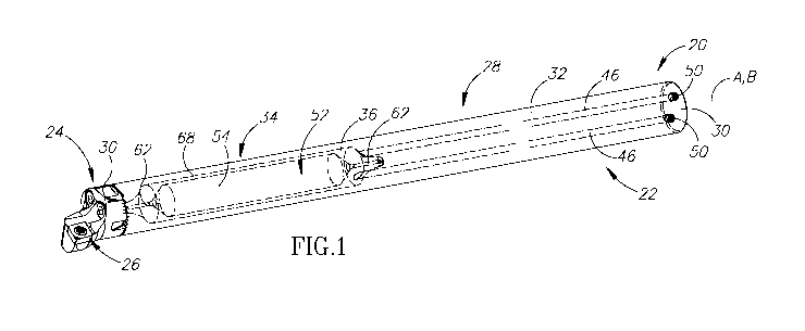
Attention is first drawn to Fig. 1 showing a cutting tool 20, for chip
removal, depicting an
aspect of the present application. The cutting tool 20 has a tool longitudinal
axis A. In
accordance with some embodiments of the subject matter of the present
application, the cutting
tool 20 can be a non-rotary cutting tool. That is to say, the cutting tool 20
is fixed and not
designed to rotate about a rotational axis. In this non-limiting example shown
in the drawings,
the cutting tool 20 is a boring bar. However, the subject matter of the
present application is not
restricted only to boring bars and could also be applicable to, for example
but not limited to, a
grooving blade. The subject matter of the present application may also be
applicable to rotary
cutting tools, such as milling and drilling tools. For such rotary cutting
tools, the cutting tool 20
is rotatable in a direction of rotation about the tool longitudinal axis A.
The cutting tool 20 includes a tool holder 22. The cutting tool 20 also
includes a cutting
portion 24 that includes at least one cutting insert 26. The at least one
cutting insert 26 is
designed to perform metal cutting operations and has a cutting edge for that
purpose. In
accordance with some embodiments of the subject matter of the present
application, the at least
.. one cutting insert 26 can be releasably attached to the tool cutting
portion 24. The cutting
portion 24 can be integrally formed with the tool holder 22. Alternatively,
the cutting portion 24
can be releasably attached to the tool holder 22. The cutting portion 24 can
be disposed at a
forward end of the tool holder 22.
Reference is now made to Fig. 2, showing the tool holder 22, depicting another
aspect of
the present application. The tool holder 22 has a tool holder longitudinal
axis B, that defines
opposite forward and rear directions DE, DR. In accordance with some
embodiments of the
subject matter of the present application, the cutting tool 20 and the tool
holder 22 can be co-
axial with each other. It should be noted that two elements (e.g. the cutting
tool 20 and the tool
holder 22 in the present case) are co-axial with each other when their
longitudinal axes are co-
incident (aligned with other).
It should further be noted that use of the terms "forward" and "rearward"
throughout the
description and claims refer to a relative position in a direction of the tool
holder longitudinal axis
B towards the left and right, respectively, in Fig. 2. Generally speaking, the
forward direction is the
direction towards the cutting portion 26.
Referring again to Fig. 2, the tool holder 22 includes a tool anti-vibration
component 28.
The tool anti-vibration component 28 is additively manufactured. The tool anti-
vibration
- 7 -
CA 03102964 2020-12-07
WO 2019/239397
PCT/IL2019/050543
component 28 is integrally formed to have unitary one-piece construction. As
used herein, an
item is said to have "unitary one-piece construction" if it results from an
additive manufacturing
process, even if more than one material is used during the additive
manufacture of that item. In
accordance with some embodiments of the subject matter of the present
application, the tool anti-
vibration component 28 can include a first metallic material. For example, the
first additively
manufactured metallic material can be steel or cemented carbide. The tool anti-
vibration
component 28 can include an additional second additively manufactured metallic
material. The
first and second additively manufactured metallic materials can be different.
For example, the
second additively manufactured metallic material can be tungsten.
It should be noted that use of the term "additively manufactured" throughout
the description
and claims refers to refers to processes used to create a three-dimensional
object in which layers of
material are formed to create an object. Examples of such processes include,
but are not limited to,
Selective Laser Melting (SLM), Selective Laser Sintering (SLS), Direct Metal
Laser Sintering
(DMLS), Fused Deposition Modeling (FDM) and 3D Printing.
Reverting to Fig. 1, in accordance with some embodiments of the subject matter
of the
present application, the tool anti-vibration component 28 can be elongated
along a component
longitudinal axis C thereof. The tool anti-vibration component 28 can be
elongated in same
direction as the tool holder 22. In particular, the tool anti-vibration
component 28 can be co-
axial with the tool holder 22. The tool anti-vibration component 28 can
include two opposite
component end surfaces 30 and a component peripheral surface 32 that extends
therebetween.
The component peripheral surface 32 can extend about the component
longitudinal axis C.
The tool holder 22 includes an anti-vibration arrangement 34 formed at the
tool anti-
vibration component 28. The tool anti-vibration arrangement 34 is designed to
reduce or
eliminate vibration of the cutting tool 20 when the cutting tool 20 performs a
metal cutting
operation. In accordance with some embodiments of the subject matter of the
present
application, the anti-vibration arrangement 34 and/or the tool anti-vibration
component 28 can be
disposed at a forward end of the cutting tool 20.
The tool anti-vibration component 28 includes a component housing portion 40
and an
anti-vibration arrangement 34.
The anti-vibration arrangement 34 includes an interior
component cavity 36 that is formed in the component housing portion 40. That
is to say, the
interior component cavity 36 is enclosed within the component housing portion
40. The
- 8 -
CA 03102964 2020-12-07
WO 2019/239397
PCT/IL2019/050543
component cavity 36 is formed by an inwardly facing cavity wall surface 38.
The cavity wall
surface 38 delimits the component cavity 36 from the component housing portion
40. The
component housing portion 40 surrounds the component cavity 36. In accordance
with some
embodiments of the subject matter of the present application, the component
cavity 36 can be
elongated along a cavity longitudinal axis D thereof. The component cavity 36
can be elongated
in the same direction as the tool holder 22. In particular, the component
cavity 36 can be co-
axial with the tool holder 22. The cavity wall surface 38 can include two
opposite cavity wall
end surfaces 42 and a cavity wall peripheral surface 44 that extends
therebetween. The cavity
wall peripheral surface 44 can extend about the cavity longitudinal axis D.
Referring in addition to Fig. 3, showing a first radial cross-sectional view
of the
component cavity 36 (taken in a plane perpendicular to the cavity longitudinal
axis D) through
the cavity wall peripheral surface 44, the component cavity 36 has a cavity
transverse cross-
section. In accordance with some embodiments of the subject matter of the
present application,
said cavity transverse cross-section can be uniform along the cavity
longitudinal axis D. The
cavity wall peripheral surface 44 can have a cylindrical shape. As shown in
Figs. 6-8, in
accordance with some other embodiments of the subject matter of the present
application, the
cavity transverse cross-section can be non-uniform along the cavity
longitudinal axis D. The
cavity wall peripheral surface 44 can taper inwardly towards the cavity
longitudinal axis D in
either direction therealong. For example, the cavity wall peripheral surface
44 can have a
conical shape.
Reverting to Fig. 5, in accordance with some embodiments of the subject matter
of the
present application, the cavity wall end surfaces 42 can taper inwardly
towards the cavity
longitudinal axis D in a direction away from the cavity wall peripheral
surface 44. For example,
the cavity wall end surfaces 42 can have a conical shape defined by a cavity
cone angle a with
respect to the cavity longitudinal axis D. The cone angle a can decrease
towards the apex.
Referring to Figs. 6-8, in accordance with some other embodiments of the
subject matter
of the present application, the cavity wall end surfaces 42 can be stepped,
having two distinct
portions, a first cavity wall end surface 45a, adjacent the cavity wall
peripheral surface 44, that
can be planar and oriented perpendicular to the cavity longitudinal axis D and
a second cavity
wall end surface 45b, distal the cavity wall peripheral surface 44, that can
have a cylindrical
shape.
- 9 -
CA 03102964 2020-12-07
WO 2019/239397
PCT/IL2019/050543
As shown in Figs. 1 and 2, in accordance with some embodiments of the subject
matter of
the present application, the tool anti-vibration component 28 can include at
least one component
through hole 46 that extends between, and opens out to, the cavity wall
surface 38 and one of the
component end surfaces 30 and the component peripheral surface 32. The at
least one
component through hole 46 allows the component cavity 36 to be filled with a
viscous fluid as
described later in the description. In some embodiments, the at least one
component through
hole 46 extends between, and opens out to, the cavity wall surface 38 and one
of the component
end surfaces 30. In some embodiments, the tool anti-vibration component 28 can
include exactly
two component through holes 46. Advantageously, this permits remnants of the
additive
manufacturing process, such as powder and particles etc., to be ejected from
one of the
component through holes 46 while the viscous fluid is injected into the
component cavity 36 via
another component through hole 46. Once the component cavity 36 is filled with
the viscous
fluid, the component cavity 36 can be sealed by at least one sealing member 50
located in the at
least one component through hole 46. The at least one sealing member 50 may
not extend
beyond the cavity wall surface 38 into the component cavity 36. The component
through hole 46
can be threaded and the at least one sealing member 50 can be a threaded
sealing screw
threadingly engaged in the component through hole 46.
Referring to Fig. 2, the anti-vibration arrangement 34 also includes a
vibration absorber
portion 52 that is disposed within the component cavity 36. The vibration
absorber portion 52
.. includes a vibration absorbing mass 54. In accordance with some embodiments
of the subject
matter of the present application, the vibration absorbing mass 54 can be
rigid. In some
embodiments, while the component housing 40 is formed from a first additive
metallic material
such as steel, the vibration absorbing mass 54 may be formed form a denser
second additive
metallic material, such as tungsten. Even so, as discussed above the vibration
absorbing mass 54
and the component housing 40 are still considered to be integrally formed to
have unitary one-
piece construction, by virtue of the additive manufacturing process.
The vibration absorbing mass 54 can be elongated along a mass longitudinal
axis E
thereof. The vibration absorbing mass 54 can be elongated in the same
direction as the tool
holder 22. In particular, the vibration absorbing mass 54 can be co-axial with
the tool holder 22.
The vibration absorbing mass 54 can include two opposite mass longitudinal
ends 60 that are
spaced apart along the mass longitudinal axis E. The vibration absorbing mass
54 can include
- 10 -
CA 03102964 2020-12-07
WO 2019/239397
PCT/IL2019/050543
two opposite mass end surfaces 56 and a mass peripheral surface 58 that
extends therebetween.
The mass peripheral surface 58 can extend about the mass longitudinal axis E.
The two mass
end surfaces 56 can be located at the two mass longitudinal ends 60,
respectively. Referring to
Fig. 2, the vibration absorbing mass 54 can have a mass length Lm measured in
its lengthwise
direction (i.e. in the direction of the mass longitudinal axis E). Referring
to Fig. 3, the vibration
absorbing mass 54 can have a mass maximum cross-sectional dimension Wm
measured in a
direction perpendicular to the mass longitudinal axis E). The mass maximum
cross-sectional
dimension Wm may be considered a mass width Wm.
Referring in addition to Fig. 3, showing the first radial cross-sectional view
of the
vibration absorbing mass 54 (taken in a plane perpendicular to the mass
longitudinal axis E)
through the mass peripheral surface 58, the vibration absorbing mass 54 has a
mass transverse
cross-section. In accordance with some embodiments of the subject matter of
the present
application, the mass transverse cross-section can be uniform for at least 60%
of the mass length
Lm along the mass longitudinal axis E. The mass peripheral surface 58 can have
a cylindrical
shape except at the mass end surfaces 56.
In accordance with some other embodiments of the subject matter of the present
application, the mass transverse cross-section can be non-uniform along the
mass longitudinal
axis E. For example, as seen in Fig. 6, the mass peripheral surface 58 can
taper inwardly
towards the mass longitudinal axis E in either direction therealong. For
example, the mass
peripheral surface 58 can have a conical shape. The vibration absorbing mass
54 can be
rotationally symmetrical about the mass longitudinal axis E.
In accordance with some embodiments of the subject matter of the present
application,
the mass end surfaces 56 can be planar and oriented perpendicular to the mass
longitudinal axis
E. In accordance with some other embodiments of the subject matter of the
present application,
the mass end surfaces 56 can taper inwardly towards the mass longitudinal axis
E in a direction
away from the mass peripheral surface 58. For example, the mass end surfaces
56 can have a
conical shape.
In accordance with some embodiments of the subject matter of the present
application,
the cavity wall peripheral surface 44 can have a shape that matches the shape
of the mass
peripheral surface 58. One or both of the two cavity wall end surfaces 42 can
have a shape that
- 11 -
CA 03102964 2020-12-07
WO 2019/239397
PCT/IL2019/050543
matches the shape of the corresponding mass end surface 56. The component
cavity 36 can
have a shape that matches the shape of the vibration absorber portion 52.
The vibration absorber portion 52 includes at least one resilient suspension
member 62.
The suspension member 62 is elastically deformable. In accordance with some
embodiments of
the subject matter of the present application, the at least one suspension
member 62 may not be
pre-loaded (that is, either compressed or stretched). The at least one
suspension member 62 can
be a spring extending helically about a suspension member longitudinal axis F
(see Fig. 9).
Alternatively, in accordance with some embodiments of the subject matter of
the present
application, the at least one suspension member 62 can be elongated along the
suspension
member longitudinal axis F. The at least one suspension member 62 can be
elongated in the
same direction as the tool holder 22. In particular, the at least one
suspension member 62 can be
co-axial with the tool holder 22. The at least one suspension member 62 can be
include two
opposite suspension member longitudinal ends 64 that are spaced apart along
the suspension
member longitudinal axis F. The at least one suspension member 62 can include
a suspension
member peripheral surface 66 that extends about the suspension member
longitudinal axis F.
Referring in addition to Fig. 4, showing a second radial cross-sectional view
of one
suspension member 62 (taken in a plane perpendicular to the suspension member
longitudinal
axis F) through the suspension member peripheral surface 66, the one
suspension member 62 has
a suspension member transverse cross-section. The suspension member peripheral
surface 66
can have a cylindrical shape. Referring to Fig.2, the at least one suspension
member 62 can have
a suspension member length Ls measured in its lengthwise direction (i.e. in
the direction of the
suspension member longitudinal axis F). Referring to Fig. 4, the at least one
suspension member
62 can have a suspension member maximum cross-sectional dimension Ws measured
in a
direction perpendicular to the suspension member longitudinal axis F). The
suspension member
maximum cross-sectional dimension Ws can be considered a suspension member
width Ws.
The vibration absorber portion 52 is integrally formed with the component
housing
portion 40 to have unitary one-piece construction therewith. The vibration
absorbing mass 54 is
connected to the component housing portion 40 at the at least one suspension
member 62. Thus,
the vibration absorbing mass 54 is suspended in the component cavity 36 by the
at least one
suspension member 62.
- 12 -
CA 03102964 2020-12-07
WO 2019/239397
PCT/IL2019/050543
In accordance with some embodiments of the subject matter of the present
application,
the at least one suspension member 62 can be connected to one of the mass
longitudinal ends 60.
The vibration absorber portion 52 can include two suspension members 62
connected to the two
mass longitudinal ends 60. The vibration absorber portion 52 can include
exactly two
suspension members 62. The suspension member peripheral surface 66 of each
suspension
member 62 can extend from a respective mass end surface 56 to a respective
cavity wall end
surface 42.
In accordance with some embodiments of the subject matter of the present
application,
the vibration absorbing mass 54 can be longer than the at least one suspension
member 62. For
example, the mass length Lm can be at least five times greater than the
suspension member
length Ls. The vibration absorbing mass 54 can be wider than the at least one
suspension
member 62. For example, the mass maximum cross-sectional dimension Wm can be
at least five
times greater than the suspension member maximum cross-sectional dimension Ws.
The anti-vibration arrangement 34 includes an oscillating space 68 formed in
the
component cavity 36. The oscillating space 68 is located between the vibration
absorber portion
52 and the component housing portion 40 (and more particularly between the
vibration absorber
portion 52 and the inwardly facing cavity wall surface 38). Stated
differently, the component
housing portion 40 and the vibration absorber portion 52 are spaced apart by
the oscillating space
68. In accordance with some embodiments of the subject matter of the present
application, the
oscillating space 68 entirely circumferentially surrounds the vibration
absorber portion 52. That
is to say, the oscillating space 68 can extend about the full (3600) angular
extent of the cavity
longitudinal axis D. The oscillating space 68 can form an internal annular
slit at the vibration
absorbing mass 54.
In accordance with some embodiments of the subject matter of the present
application,
the vibration absorbing mass 54 is connected to the component housing portion
40 only at the at
least one suspension member 62. Thus, the oscillating space 68 is devoid of
any separate
additional solid element, such as an o-ring, disposed between and abutting the
cavity wall surface
38 and the mass end surfaces 56 and/or the Mass Peripheral Surface 58 (as
shown in, for
example, US 7,234,379).
The vibration absorbing mass 54 is configured to oscillate within the
oscillating space 68
upon elastic deformation of the at least one suspension member 62. Stated
differently, the
- 13 -
CA 03102964 2020-12-07
WO 2019/239397
PCT/IL2019/050543
vibration absorbing mass 54 is oscillatingly displaceable within the
oscillating space 68 when the
at least one suspension member 62 undergoes elastic deformation. In accordance
with some
embodiments of the subject matter of the present application, the elastic
deformation can be
caused by a tensile load applied by the vibration absorbing mass 54 on the at
least one
suspension member 62.
In the embodiment seen in Fig. 2, two suspension members 62 are used to
connect the
vibration absorbing mass 54 to the component housing portion 40 ¨ one
suspension member 54
at each of the two opposite ends of the vibration absorbing mass 54. In some
embodiments,
however, only a single suspension member 62 may be used to connect the
vibration absorbing
mass 54 to the component housing portion 40. In such case, the vibration
absorbing mass 54 is
cantilevered within the component cavity 36.
When the cutting tool 20 encounters a workpiece, it is susceptible to
vibration.
Typically, for turning or milling cutting operations the vibrations are
lateral vibrations.
Typically, for drilling cutting operations, the vibrations are torsional
vibrations. The vibration
absorbing mass 54 oscillates at a vibration frequency. The anti-vibration
arrangement is 34
designed to provide the vibration absorbing mass 54 with a vibration frequency
close or identical
to the natural frequency of the cutting tool 20, thereby reducing or
eliminating vibration of the
cutting tool 20.
Advantageously, the anti-vibration arrangement 34 can be tunable (so that the
vibration
frequency of the vibration absorbing mass 54 matches the natural frequency of
the cutting tool
20) without the need to disassemble any separable parts. One or more
mechanisms, alone or in
combination, can be used to alter the vibration frequency at which the
vibration absorbing mass
54 oscillates. In one non-limiting example, the at least one suspension member
62 can be pre-
loaded. For example, referring to Fig. 6, the anti-vibration arrangement 34
can include a tuning
member 70 that protrudes into the oscillating space 68. The tuning member 70
can abut one of
the at least one suspension members 62, thereby adjusting the elastic
properties of the at least
one suspension member 62. In particular, the tool anti-vibration component 28
can include a
threaded tuning through hole 72 that extends between, and opens out to, the
cavity wall surface
38 and the component peripheral surface 32. The tuning member 70 can be a
threaded
adjustment screw threadingly engaged in the tuning through hole 72.
- 14 -
CA 03102964 2020-12-07
WO 2019/239397
PCT/IL2019/050543
The oscillating space 68 can be filled with the viscous fluid, so that the
viscous fluid
circumferentially surrounds the vibration absorbing mass 54 and causes a
damping effect on the
vibration absorbing mass 54. Various viscous fluids having different
viscosities can be used in
order to adjust the damping effect.
The vibration absorbing mass 54 can be manufactured from the second additively
manufactured metallic material while the component housing portion 40 can be
manufactured
from the first additively manufactured metallic material. In such a
configuration, the weight of
the vibration absorbing mass 54 can be adjusted without changing its
dimensions.
It should be further be noted that another feature of the subject matter of
the present
application is that the anti-vibration arrangement 34 is suitable for
neutralizing lateral vibrations
and torsional vibrations.
Although the subject matter of the present application has been described to a
certain
degree of particularity, it should be understood that various alterations and
modifications could
be made without departing from the spirit or scope of the invention as
hereinafter claimed.
Referring to Fig. 7, for example, the tool anti-vibration component 28 can
include an
additional second anti-vibration arrangement 34. The tool holder 22 can
include an additional
second tool anti-vibration component 28 (not shown). Thus, the tool holder 22
can include two
anti-vibration arrangements 34. In such a configuration, the two oscillating
spaces 68 can be in
fluid communication with each other via the component through holes 46.
Referring to Fig. 8, the tool holder 22 can be modular. That is say, the tool
holder 22 can
include a shank component 74 separately manufactured from the tool anti-
vibration component
28 and connected thereto to form the tool holder 22. In some embodiments, the
tool anti-
vibration component 28 may be inserted into a cavity formed in the shank
component 74. The
tool anti-vibration component 28 can be connected to the shank component 74
by, for example,
brazing, welding, threading engagement, etc. Alternatively, the shank
component 74 can include
a shank sleeve portion 76 with the tool anti-vibration component 28 being
connected therein via
an interference fit. The shank component 74 can be additively manufactured.
Alternatively, the
shank component 74 can be manufactured by a conventional subtractive
technology so that the
tool holder 22 is so-called "hybrid".
Alternatively, as best seen in Fig. 1, the tool holder 22 can be non-modular,
where the
tool anti-vibration component 28 is integrally formed with the tool holder 22
in a unitary one-
- 15 -
CA 03102964 2020-12-07
WO 2019/239397
PCT/IL2019/050543
piece construction such that the tool anti-vibration component 28 is the tool
holder's shank.
Advantageously, in such a configuration the tool holder 22 needs no post-
manufacturing
assembly of separate parts.
Referring to Fig. 9, the tool anti-vibration component 28 can include an
internal coolant
channel 78 which extends internally through the at least one suspension member
62 and the
vibration absorbing mass 54. In the configuration where the at least one
suspension member 62
is a helical, the internal coolant channel 78 can also extends helically about
the same axis. The
vibration absorbing mass 54 can include a mass recess 80 and the least one
suspension member
62 can be connected to the vibration absorbing mass 54 in the mass recess 80.
Advantageously
this can increase the length of the least one suspension member 62 without
increasing the length
of the tool anti-vibration component 28.
Although the subject matter of the present application has been described to a
certain
degree of particularity, it should be understood that various alterations and
modifications could
be made without departing from the spirit or scope of the invention as
hereinafter claimed.
- 16 -