Note: Descriptions are shown in the official language in which they were submitted.
P19CWD331CA01
DIMMER SWITCH SYSTEM WITH SINGLE WIRE TWO-WAY
COMMUNICATION ARCHITECTURE
BACKGROUND
Field
The disclosed concept relates generally to dimmer switches, and in
particular, to dimmer switch systems with multiple dimmer switches. The
disclosed
concept also relates to communication structures within dimmer switch systems.
Background Information
Dimmer switches provide a dimming function for loads such as lights.
Dimmer switch systems may comprise a single dimmer or multiple dimmers
arranged,
for example, as a master dimmer and one or more accessory dimmers. Other
devices,
such as a three-way toggle switch may also be employed in dimmer switch
systems. In a
dimmer system comprising multiple dimmers or other devices, the multiple
dimmers or
other devices likely need a mechanism to communicate with each other. For
example,
accessory dimmers need to be able to communicate inputs received at the
accessory
dimmer to the master dimmer in order for the master dimmer to correspondingly
adjust
dimming based on the inputs received at the accessory dimmer. Similarly, the
master
dimmer may need to provide status updates to the accessory dimmers or other
devices
connected to it. Communication between dimmers or other devices may be
facilitated by
either one or more traveler wires connecting the dimmers or other devices.
Systems with
a single traveler wire can be problematic as conflicts can arise when multiple
dimmers or
other devices simultaneously attempt to communicate via the single traveler
wire.
There is thus room for improvement within dimmer switch systems.
SUMMARY
These needs and others are met by embodiments of the disclosed concept
in which a dimmer switch system includes a master dimmer and at least one
accessory
dimmer, where the master dimmer and accessory dimmer(s) communicate using a
single
traveler wire, with the master dimmer transmitting signals during one portion
of the
power supply phase and the accessory dimmer transmitting signals during
another portion
-1-
Date Recue/Date Received 2020-12-18
P19CWD331CA01
of the power supply phase. In addition, each of the master dimmer and
accessory
dimmer(s) comprises a load status indicator that reflects the current dimming
level of a
load connected to the master dimmer.
In accordance with one aspect of the disclosed concept, a dimmer switch
system for dimming a load comprises: a master dimmer structured to be
electrically
connected to a power source and the load and to control dimming of the load by
regulating power provided from the power source to the load; and at least one
accessory
dimmer structured to be electrically connected to the master dimmer via a
traveler
conductor; wherein the master dimmer is structured to generate a first control
signal on
the traveler conductor during one of a positive or negative half-cycle of
power from the
power source, and wherein the at least one accessory dimmer is structured to
generate a
second control signal on the traveler conductor during the other of the
positive or
negative half-cycle of power from the power source.
In accordance with another aspect of the disclosed concept, a method of
dimming a load comprises: electrically connecting a master dimmer between a
power
source and the load and controlling dimming of the load by regulating power
provided
from the power source to the load with the master dimmer; electrically
connecting at least
one accessory dimmer to the master dimmer via a traveler conductor;
structuring the
master dimmer to generate a first control signal on the traveler conductor
during one of a
positive or negative half-cycle of power from the power source; and
structuring the at
least one accessory dimmer to generate a second control signal on the traveler
conductor
during the other of the positive or negative half-cycle of power from the
power source.
In accordance with another aspect of the disclosed concept, a dimmer
switch system for dimming a load, the dimmer switch system comprises: a master
dimmer structured to be electrically connected to a power source and the load
and to
control dimming of the load by regulating power provided from the power source
to the
load; and at least one accessory dimmer structured to be electrically
connected to the
master dimmer via a traveler conductor; wherein the master dimmer is
structured to
generate a first control signal on the traveler conductor, and wherein the at
least one
accessory dimmer is structured to generate a second control signal on the
traveler
conductor.
-2-
Date Recue/Date Received 2020-12-18
P19CWD331CA01
BRIEF DESCRIPTION OF THE DRAWINGS
A full understanding of the disclosed concept can be gained from the
following description of the preferred embodiments when read in conjunction
with the
accompanying drawings in which:
FIG. 1 is a schematic diagram of a dimmer switch system including a
master dimmer and number of accessory dimmers in accordance with an example
embodiment of the disclosed concept;
FIG. 2A is a schematic diagram of the master dimmer of FIG. 1 shown in
more detail in accordance with an example embodiment of the disclosed concept;
FIG. 2B is a schematic diagram of an accessory dimmer of FIG. 1 shown
in more detail in accordance with an example embodiment of the disclosed
concept;
FIGS. 3A and 3B are graphs of predetermined time delays of signals
transmitted from the master dimmer and an accessory dimmer during single
polarity half-
cycles of power from the power supply in accordance with an example embodiment
of
the disclosed concept;
FIG. 4 shows graphs depicting transmission of control signals by the
master dimmer and an accessory dimmer during opposite polarity half-cycles of
power in
accordance with an example embodiment of the disclosed concept.
FIG. 5 is a flow chart of a first method of dimming a load in accordance
with an example embodiment of the disclosed concept;
FIG. 6 is a flow chart of a second method of dimming a load in accordance
with an example embodiment of the disclosed concept; and
FIG. 7 is a flow chart of a third method of dimming a load in accordance
with an example embodiment of the disclosed concept.
DESCRIPTION OF THE PREFERRED EMBODIMENTS
As employed herein, the term "processing unit" shall mean a
programmable analog and/or digital device that can store, retrieve, and
process data; a
microprocessor; a microcontroller; a microcomputer; a central processing unit;
or any
suitable processing device or apparatus.
-3-
Date Recue/Date Received 2020-12-18
P19CWD331CA01
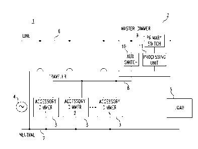
FIG. 1 is a schematic diagram of a dimmer switch system 1 including a
master dimmer 2 and number of accessory dimmers 3 in accordance with an
example
embodiment of the disclosed concept. A number N of accessory dimmers 3 is
shown in
FIG. 1, and it will be appreciated that dimmer switch system 1 can include one
accessory
dimmer 3 or more than one accessory dimmer 3 without departing from the scope
of the
disclosed concept. The master dimmer 2 and accessory dimmers 3 are
electrically
connected to a power source 4 via line and neutral conductors 6,7 and are
powered by the
power source 4. The master dimmer 2 is electrically connected to the power
source 4 and
a load 5. Master dimmer 2 and accessory dimmers 3 are electrically connected
to one
another by a traveler conductor 8. Master dimmer 2 includes a primary
semiconductor
switch 9, a master auxiliary semiconductor switch 10, and a master processing
unit 11. In
one exemplary embodiment, primary semiconductor switch 9 and master auxiliary
semiconductor switch 10 are TRIAC switches. However, it will be appreciated
that other
types of semiconductor switches may be employed without departing from the
scope of
the disclosed concept. Primary semiconductor switch 9 is electrically
connected between
power source 4 and load 5 by line conductor 6 and directly regulates the
amount of power
provided to load 5 by power source 4. Dimming of the load is achieved by
changing the
conduction angle of primary semiconductor switch 9. Adjusting the conduction
angle of
primary semiconductor switch 9 produces proportional adjustments to the amount
of
power provided to load 5, for example by performing forward or reverse phase
cutting of
the power provided to the load 5.
FIGS. 2A and 2B are schematic diagrams of master dimmer 2 and
accessory dimmers 3 of FIG. 1 shown in more detail in accordance with example
embodiments of the disclosed concept. In FIG. 2A, master dimmer 2 further
includes a
master load status indicator 12. Master load status indicator 12 provides an
indication of
how much power is being provided to the load. In one exemplary embodiment,
master
load status indicator 12 is an indicator (e.g., a series of LEDs) that
provides a visual
indication of a dimming level of the load 5. However, it will be appreciated
that other
types of indicators may be employed to indicate how much power is being
provided to
the load without departing from the scope of the disclosed concept. Master
auxiliary
semiconductor switch 10 is electrically connected between line conductor 6 and
traveler
-4-
Date Recue/Date Received 2020-12-18
P19CWD331CA01
conductor 8, which in turn is connected to accessory dimmers 3. Master
processing unit
11 is electrically connected to primary semiconductor switch 9 and auxiliary
semiconductor switch 10. Master processing unit 11 is structured to adjust the
conduction angle of primary semiconductor switch 9 based on, for example,
signals
received from accessory dimmers 3 or adjustments received at master dimmer 2.
It will
be appreciated that adjustments received at master dimmer 2 may be received
through
user input to controls or other means on master dimmer 2 without departing
from the
scope of the disclosed concept. Master processing unit 11 is also structured
to control
master auxiliary semiconductor switch 10 to selectively allow power to flow
from line
conductor 6 to traveler conductor 8. Said power flowing to traveler conductor
8 operates
as a control signal that is provided to other components electrically
connected to traveler
conductor 8.
In FIG. 2B, accessory dimmer 3 includes an accessory auxiliary
semiconductor switch 13, an accessory processing unit 14, and an accessory
load status
indicator 15. In one exemplary embodiment, accessory load status indicator 15
is an
indicator (e.g., a series of LEDs) that provides a visual indication of a
dimming level of
the load 5. However, it will be appreciated that other types of indicators may
be
employed to indicate how much power is being provided to the load without
departing
from the scope of the disclosed concept. Accessory auxiliary semiconductor
switch 13 is
electrically connected between line conductor 6 and traveler conductor 8.
Accessory
auxiliary semiconductor switch 13 is also electrically connected to accessory
processing
unit 14. Accessory auxiliary processing unit 14 is structured to control
accessory
auxiliary switch 13 to selectively allow power to flow from line conductor 6
to traveler
conductor 8. Said power flowing to traveler conductor 8 operates as a control
signal that
is provided to other components electrically connected to traveler conductor
8.
In an example embodiment of dimmer switch system 1 of the disclosed
concept, only primary semiconductor switch 9 directly regulates the amount of
power
provided to load 5 by power source 4. When master dimmer 2 is adjusted for the
purpose
of dimming the load, master processing unit 11 adjusts the conduction angle of
primary
semiconductor switch 9 to proportionally adjust the power provided to load 5
(e.g., by
performing a forward or reverse phase cut of the power), and updates master
load status
-5-
Date Recue/Date Received 2020-12-18
P19CWD331CA01
indicator 12 to indicate the dimming level of load 5 after the adjustment.
Master
processing unit 11 subsequently controls master auxiliary semiconductor switch
10 to
close to allow power from line conductor 6 to flow to traveler conductor 8,
which acts as
a control signal that is received by all accessory dimmers 3 connected to
traveler
conductor 8 indicating the dimming level of load 5. Information is encoded
into the
control signal based on an amount of time after a zero crossing in power from
power
source 4 that power from line conductor 6 is allowed to flow onto traveler
conductor 8.
For example, generating the control signal 1.5ms after the zero crossing may
indicate a
first dimming level and generating the control signal 2.5ms after the zero
crossing may
indicate a second dimming level. Accessory processing unit 14 within each
accessory
dimmer 3 updates its accessory load status indicator 15 based on the control
signal
received via traveler conductor 8 to indicate the dimming level of load 5.
In another exemplary embodiment of the disclosed concept, master load
status indicator 12 and accessory load status indicator 15 each contain a
series of LEDs
wherein each LED indicates a specific dimming level, such that only one LED is
lit at a
time to indicate the current dimming level of the load. In this exemplary
embodiment,
for a dimmer system with seven possible levels of dimming, master load status
indicator
12 and accessory load status indicator 15 would be comprised of seven LEDs,
with LED
1 corresponding to the lowest level of dimming, LED 7 corresponding to the
highest level
of dimming, and LED 4 corresponding to an intermediate level of dimming.
However, it
will be appreciated that other types of indicators may be employed to indicate
how much
power is being provided to the load without departing from the scope of the
disclosed
concept. It will also be appreciated that in some example embodiments, as will
be
described in more detail herein, the dimming level of load 5 may include an
on/off
designation.
In order to change the amount of power provided to load 5 using an
accessory dimmer 3, an accessory dimmer 3 similarly transmits a control signal
via
traveler conductor 8 to master dimmer 2 to initiate the desired change. The
control signal
from an accessory dimmer 3 to master dimmer 2 may be a command to turn off,
turn on,
dim up, or dim down load 5, for example. After an accessory dimmer 3 is
adjusted for
the purpose of dimming load 5, accessory processing unit 14 controls accessory
auxiliary
-6-
Date Recue/Date Received 2020-12-18
P19CWD331CA01
semiconductor switch 13 to allow power to flow from line conductor 6 onto
traveler
conductor 8, which serves as a control signal to master processing unit 11
indicative of
the adjustment to the accessory dimmer 3. Master processing unit 11 then
adjusts the
conduction angle of primary semiconductor switch 9 to adjust the power
provided to load
5 based on the control signal, and updates master load status indicator 12 to
indicate the
dimming level of load 5 after the adjustment. Master processing unit 11
subsequently
controls master auxiliary semiconductor switch 10 to allow power to flow from
line
conductor 6 onto traveler conductor 8, which serves as a control signal to all
accessory
dimmers 3 connected to traveler conductor 8 indicating the dimming level of
load 5 after
the adjustment. Accessory processing units 14 within each accessory dimmer 3
update
their accessory load status indicators 15 to indicate the dimming level of
load 5.
In one exemplary embodiment of dimmer switch system 1 of the disclosed
concept, if a user of dimmer switch system 1 pushes a "DIM UP" or "DIM DOWN"
button of an accessory dimmer 3 and continues to hold the button down, the
accessory
.. dimmer 3 will continue to transmit the corresponding control signal to
master dimmer 2
via traveler conductor 8 while the button is held down and master dimmer 2
will continue
to update the dimming level of load 5 and transmit corresponding control
signals to
accessory dimmers 3 to provide updates regarding the dimming level of load 5.
If master
dimmer 2 determines that the minimum or maximum dimming level has been
reached,
but the user continues to hold the button down, master dimmer 2 may cease to
further
adjust the dimming level of load 5 and instead just continue to transmit
control signals to
accessory dimmers 3 indicating the dimming level of load 5.
The communication scheme of dimmer switch system 1 utilizes only one
traveler conductor 8 and is bidirectional, such that master dimmer 2 is able
to transmit
signals to accessory dimmers 3 through traveler conductor 8, and accessory
dimmers 3
are also able to transmit signals to master dimmer 2 through traveler
conductor 8. Power
provided by power source 4 is AC and thus has both positive half-cycles and
negative
half-cycles of power. FIG. 3A shows a graph of a positive half-cycle 300 of
power with
control signals 301 transmitted after various time delays 302, 303, 304, 305
from the zero
.. edge crossing 310 for the positive half-cycle 300 of power. FIG. 3B shows a
graph of a
negative half-cycle 350 of power with control signals 351 transmitted after
various time
-7-
Date Recue/Date Received 2020-12-18
P19CWD331CA01
delays 352, 353, 354, 355 from the zero edge crossing 360 for the negative
half-cycle of
power. Bidirectional communication in dimmer switch system 1 is achieved by
either
assigning master dimmer 2 to transmit control signals only during positive
half-cycles
300 and assigning accessory dimmers 3 to transmit control signals only during
negative
.. half-cycles 350, or by assigning master dimmer 2 to transmit control
signals only during
negative half-cycles 350 and assigning accessory dimmers 3 to transmit control
signals
only during positive half-cycles 300. It will be appreciated that, so long as
master
dimmer 2 transmits control signals during the half-cycle of power opposite in
polarity
from the half-cycle of power in which accessory dimmers 3 transmit control
signals,
either type of dimmer may transmit signals during positive half-cycles 300 and
either
type of dimmer may transmit control signals negative half-cycles 350 without
departing
from the scope of the disclosed concept. Master processing unit 11 and
accessory
processing units 14 all contain edge detection circuitry such that, at any
given point in
time, all of the processing units know when the last zero edge crossing 310 or
360 for the
.. current polarity half-cycle of power occurred and whether the power flowing
through the
dimmer switch system is in a positive half-cycle 300 or a negative half-cycle
350.
The dimmers may communicate, for example, load dimming status and
load dimming commands to one another by transmitting control signals 301 or
351 via
traveler conductor 8. As described above, the control signals are generated in
an example
embodiment of the disclosed concept by controlling a master or auxiliary
semiconductor
switch 10, 13 to allow power to flow from line conductor 6 onto traveler
conductor 8 a
predetermined time delay from a zero edge crossing 310 or 360. Master
processing unit
11 and accessory processing units 14 are all programmed to cause control
signals 301 or
351 with predetermined time delays of various lengths, such as 302, 303, 304,
305, 352,
353, 354, or 355, such that each unique length of time delay from a zero edge
crossing
310 or 360 corresponds to a unique control signal. The depiction of time
delays 302,
303, 304, 305, 352, 353, 354, or 355 is for illustrative purposes, and it will
be appreciated
that signals can be transmitted on time delays of any length from zero edge
crossings 310
and 360 without departing from the scope of the disclosed concept. The dimming
level
.. of the load 5 is based on the conduction angle of the primary semiconductor
switch 9, so
-8-
Date Recue/Date Received 2020-12-18
P19CWD331CA01
the dimming level is synonymous with the conduction angle of the primary
semiconductor switch 9.
In one example, master dimmer 2 is assigned to transmit signals only
during positive half-cycles 300 and accessory dimmers 3 are assigned to
transmit signals
.. only during negative half-cycles 350. Both master processing unit 11 and
accessory
processing units 14 start timers upon detecting a zero edge crossing 310 or
360. When
master processing unit 11 needs to transmit a signal 301 to accessory dimmers
3 to
indicate the dimming level of load 5 after an adjustment to the conduction
angle of the
primary semiconductor switch 9, master processing unit 11 determines the
conduction
angle of the primary semiconductor switch 9, waits a length of time equal to
the
predetermined time delay 305 corresponding to the conduction angle, and turns
master
auxiliary semiconductor switch 10 to an ON state. When master auxiliary
semiconductor
switch 10 turns to an ON state, accessory processing units 14 detect the
control signal on
traveler conductor 8 and stop their timers. Accessory processing units 14 then
update
their accessory load status indicators 15 based on the control signal. The
time measured
by the timer of accessory processing unit 14 is equal to the predetermined
time delay 305
on which master processing unit 11 turned master auxiliary semiconductor
switch 10 to
an ON state. Accessory processing units 14 interpret the time delay measured
by their
timers to represent the dimming level associated with the predetermined time
delay 305
and update their accessory load status indicators 15 accordingly.
In the same example, when one of accessory processing units 14 needs to
transmit a signal to master dimmer 2 indicating a desired change to the
dimming level of
load 5 based on an adjustment made to an accessory dimmer 3, the accessory
processing
unit 14 of the adjusted accessory dimmer 3 waits a length of time equal to the
predetermined time delay 355 corresponding to the desired dimming level
adjustment,
and turns its accessory auxiliary semiconductor switch 13 to an ON state. When
the
accessory auxiliary semiconductor switch 13 turns to an ON state, master
processing unit
11 detects the control signal on traveler conductor 8 and stops its timer.
Master
processing unit 11 changes the conduction angle of primary semiconductor
switch 9 and
updates master load status indicator 12 based on the control signal. The time
measured
by the timer of master processing unit 11 is equal to the predetermined time
delay 355 on
-9-
Date Recue/Date Received 2020-12-18
P19CWD331CA01
which the accessory processing unit 14 turned the accessory auxiliary
semiconductor
switch 13 to an ON state. Master processing unit 11 interprets the time delay
measured
by its timer to represent the dimming level associated with the predetermined
time delay
355 and updates the conduction angle of primary semiconductor switch 9 and
master load
status indicator 12 accordingly. Master processing unit 11 subsequently
transmits a
signal to all accessory dimmers 3 to update their load status indicators 15 as
previously
described.
In another example, master dimmer 2 is again assigned to transmit signals
only during positive half-cycles 300 and accessory dimmers 3 are assigned to
transmit
signals only during negative half-cycles 350. Both master processing unit 11
and
accessory processing units 14 start timers upon detecting a zero edge crossing
310 or 360.
In this example, during every other positive half-cycle 300, master processing
unit 11
transmits a signal 301 to accessory dimmers 3 to indicate whether master
dimmer 2 is ON
or OFF. During the other of the every other positive half-cycle 300, master
processing
unit 11 transmits a signal 301 to accessory dimmers 3 indicating the
conduction angle of
primary semiconductor switch 9. During a positive half-cycle 300 designated
for
communicating the DIMMER ON/DIMMER OFF state of master dimmer 2, master
processing unit 11 determines if the conduction angle of the primary
semiconductor
switch 9 is that of a DIMMER ON or DIMMER OFF state, waits a length of time
equal
to the predetermined time delay 305 corresponding to a DIMMER ON state or
DIMMER
OFF state as appropriate, and turns master auxiliary semiconductor switch 10
to an ON
state. When master auxiliary semiconductor switch 10 turns to an ON state,
accessory
processing units 14 detect the control signal on traveler conductor 8 and stop
their timers.
Accessory processing units 14 then update their accessory load status
indicators 15 based
on the control signal. The time measured by the timer of accessory processing
unit 14 is
equal to the predetermined time delay 305 on which master processing unit 11
turned
master auxiliary semiconductor switch 10 to an ON state. Accessory processing
units 14
interpret the time delay measured by their timers to represent the DIMMER
ON/DIMMER OFF state of master dimmer 2 associated with the predetermined time
delay 305 and update their accessory load status indicators 15 accordingly.
The time
delay 305 representing a DIMMER ON state of master dimmer 2 and the time delay
305
-10-
Date Recue/Date Received 2020-12-18
P19CWD331CA01
representing a DIMMER OFF state of master dimmer 2 are unique compared to one
other
and unique compared to the time delays 305 representing each of the possible
levels of
dimming of load 5. For example, if accessory processing units 14 receive a
DIMMER
ON control signal from master processing unit 11 while accessory load status
indicators
15 already indicate that master dimmer 2 is ON, i.e. while accessory load
status
indicators 15 indicate some level of dimming of load 5, then accessory load
status
indicators 15 would not change their status. If however, accessory load status
indicators
receive a DIMMER OFF control signal from the master processing unit 11 while
accessory load status indicators 15 indicate that master dimmer 2 is ON,
accessory load
10 status indicators 15 would change their status to indicate an OFF state.
If accessory load
status indicators 15 receive a DIMMER ON control signal from master processing
unit
11 while accessory load status indicators 15 indicate that master dimmer 2 is
OFF,
accessory load status indicators 15 would not change until the next positive
half-cycle,
when they receive a control signal from master processing unit 11 indicating
the current
15 conduction angle of primary semiconductor switch 9.
In some example embodiments, master dimmer 2 may periodically (e.g.,
without limitation, every 1 sec.) transmit dimming level updates to accessory
dimmers 3.
Alternatively or additionally, accessory dimmers 3 may periodically, or on an
on-demand
basis, request dimming level updates from master dimmer 2. For example, an
accessory
dimmer 3 just powering on may request that master dimmer 2 provide an update
on the
dimming level of load 5, and, in response, master dimmer 2 may provide a
current
dimming level of load 5 to all accessory dimmers 3 via traveler conductor 8.
The time
delay 305 representing a request for the current dimming level of load 5 is
unique
compared to the time delays 305 representing each of the possible levels of
dimming of
load 5.
In one exemplary embodiment of the disclosed concept, each of the
accessory processing units 14 and master processing unit 11 are programmed
with an
error tolerance such that, if any noise affects the transmission time of the
control signal
generated by master auxiliary semiconductor switch 10 turning to an ON state
or
accessory auxiliary semiconductor switch 13 turning to an ON state, accessory
processing
units 14 and master processing unit 11 would be able to correctly interpret
the
-11 -
Date Recue/Date Received 2020-12-18
P19CWD331CA01
information encoded in the transmitted control signal. For example, if each
accessory
processing unit 14 and master processing unit 11 is programmed to have a
tolerance of
200 s, and a control signal generated 1.5 ms after a zero crossing was not
received by
each accessory processing unit 14 or master processing unit 11 until 1.65 ms
after the
zero crossing, each accessory processing unit 14 or master processing unit 11
would still
be able to correctly interpret the encoded information as if the signal had
been received
1.5 ms after the zero crossing. Similarly, in the same example with a
tolerance of 200
s, if a control signal generated 1.5 ms after a zero crossing was received
1.35 ms after
the zero crossing by each accessory processing unit 14 or master processing
unit 11, each
accessory processing unit 14 or master processing unit 11 would still be able
to correctly
interpret the encoded information as if the signal had been received 1.5 ms
after the zero
crossing. A tolerance of 200 i.is is used for illustrative purposes only and
it will be
appreciated that error tolerances of other magnitudes may be employed without
departing
from the scope of the disclosed concept.
FIG. 4 shows graphs depicting: (1) master dimmer 2 transmitting signals
301 during positive half-cycles of power 300, (2) accessory dimmers 3
receiving and
decoding signals 301 transmitted by master dimmer 2 during positive half-
cycles of
power 300, (3) an accessory dimmer 3 transmitting signals 351 during negative
half-
cycles of power 350, and (4) master dimmer 2 receiving and decoding signals
351
transmitted by accessory dimmer 3 during negative half-cycles of power 350 in
accordance with an example embodiment of the disclosed concept.
The top graph of FIG. 4 depicts an example waveform of power flowing
through traveler conductor 8. As shown in the top graph of FIG. 4, a first
control signal
41 is generated on traveler conductor 8 by master dimmer 2 a first
predetermined time
into a positive half-cycle of power. A second control signal 42 is generated
on traveler
conductor 8 by an accessory dimmer 3 a second predetermined time into a
negative half-
cycle of power. The middle graph of FIG. 4 depicts an example of decoded
control
signals 43 received by an accessory dimmer 3. As shown in the middle graph of
FIG. 4,
the decoded control signals 43 begin each positive half-cycle in a high state
and change
to a low state each time a control signal is generated on the traveler
conductor 8 during a
positive half-cycle. These decoded control signals 43 can be used to determine
the
-12-
Date Recue/Date Received 2020-12-18
P19CWD331CA01
predetermined time delay of the control signal from master dimmer 2, and the
accessory
dimmer 3 can, in turn, perform an action associated with the predetermined
time delay.
The bottom graph of FIG. 4 depicts an example of decoded control signals 44
received by
master dimmer 2. As shown in the bottom graph of FIG. 4, the decoded control
signals
44 begin each positive half-cycle in the low state and change to a high state
each time a
control signal is generated on the traveler conductor 8 during a negative half-
cycle.
These decoded control signals 44 can be used to determine the predetermined
time delay
of the control signal from an accessory dimmer 3, and the master dimmer 2 can,
in turn,
perform an action associated with the predetermined time delay. The graphs
shown in
FIG. 4 depict master dimmer 2 transmitting signals during positive half-phases
of power
and accessory dimmers 3 transmitting signals during negative half-phases of
power;
however, it will be appreciated that master dimmer 2 may transmit signals
during
negative half-phases of power while accessory dimmers 3 transmit signals
during positive
half-phases of power without departing from the scope of the disclosed
concept. It will
-- be appreciated that the graphs shown in FIG. 4 depict a non-limiting
example to aid in
understanding the communication scheme between master dimmer 2 and accessory
dimmers 3. The various states of the signals and their timing may be modified
without
departing from the scope of the disclosed concept.
FIG. 5 is a flowchart of a method of dimming a load connected to a
dimmer switch system in accordance with an example embodiment of the disclosed
concept. The method of FIG. 5 may be employed, for example, with dimmer switch
system 1 shown in FIGS. 1, 2A, and 2B and is described in conjunction with
dimmer
switch system 1 shown in FIGS. 1, 2A, and 2B. However, it will be appreciated
that the
method may be employed in other devices as well without departing from the
scope of
the disclosed concept. The method begins at 501 where master dimmer 2 is
provided. At
502, accessory dimmer 3 is provided. At 503, master dimmer 2 generates a first
control
signal. The first control signal is generated in one of the positive or
negative half-cycle
of power from power source 4 and is generated a first predetermined time after
a zero
crossing beginning said half-cycle. At 504, an action associated with the
first control
-- signal (e.g., an action associated with the first predetermined time after
the zero crossing)
is performed. One example of an action associated with the first control
signal is
-13-
Date Recue/Date Received 2020-12-18
P19CWD331CA01
updating accessory load status indicator 15. However, it will be appreciated
that other
actions may be associated with the first control signal without departing from
the scope
of the disclosed concept. At 505, accessory dimmer 3 generates a second
control signal.
The second control signal is generated in the other of the positive or
negative half-cycle
of power from power source 4 and is generated a second predetermined time
after a zero
crossing beginning said half-cycle. At 506, an action associated with the
second control
signal (e.g., an action associated with the second predetermined time after
the zero
crossing) is performed. One example of an action associated with the second
control
signal is adjusting the conduction angle of primary semiconductor switch 9.
However, it
will be appreciated that other actions may be associated with the second
control signal
without departing from the scope of the disclosed concept.
FIG. 6 is a flowchart of a second method of dimming a load connected to a
dimmer switch system in accordance with an example embodiment of the disclosed
concept. The method of FIG. 6 may be employed, for example, with dimmer switch
system 1 shown in FIGS. 1, 2A, and 2B and is described in conjunction with
dimmer
switch system 1 shown in FIGS. 1, 2A, and 2B. However, it will be appreciated
that the
method may be employed in other devices as well without departing from the
scope of
the disclosed concept. The method of FIG. 6 is an example of updating load
status
indicators based on an adjustment in dimming at a master dimmer in accordance
with an
example embodiment of the disclosed concept. The method begins at 601 where
the
dimming of load 5 is adjusted by master dimmer 2. It will be appreciated that
in an
example embodiment, the dimming level of load 5 may include an on/off
designation
such that the adjustment by master dimmer 2 to the dimming level of load 5
includes
turning load 5 on/off. At 602, master load status indicator 12 is updated in
master
dimmer 2 by master processing unit 11. At 603, a control signal is generated
by master
dimmer 2. The control signal is generated in one of the positive or negative
half-cycle of
power from power source 4 at a predetermined time associated with the dimming
level of
load 5. At 604, the control signal is transmitted by master dimmer 2 to
accessory
dimmers 3 via traveler conductor 8. At 605, the control signal is received by
an
accessory dimmer 3. At 606, accessory load status indicator 15 of the
accessory dimmer
3 is updated by accessory processing unit 14 based on the control signal.
-14-
Date Recue/Date Received 2020-12-18
P19CWD331CA01
FIG. 7 is a flowchart of a third method of dimming a load connected to a
dimmer switch system in accordance with an example embodiment of the disclosed
concept. The method of FIG. 7 may be employed, for example, with dimmer switch
system 1 shown in FIGS. 1, 2A, and 2B and is described in conjunction with
dimmer
switch system 1 shown in FIGS. 1, 2A, and 2B. However, it will be appreciated
that the
method may be employed in other devices as well without departing from the
scope of
the disclosed concept. The method begins at 701 where an adjustment to the
dimming of
load 5 is initiated by an accessory dimmer 3, for example by a user
interacting with
dimming controls on the accessory dimmer 3. At 702, a control signal is
generated by the
accessory dimmer 3 during the other of the positive or negative half-cycle of
power from
power source 4 (i.e., the half-cycle not used by master dimmer 2). The control
signal is
generated a predetermined time after a zero crossing starting the half-cycle
and the
predetermined time is associated with the adjustment to the dimming (e.g.,
turn off, turn
on, dim up, or dim down). At 703, the control signal is transmitted by the
accessory
dimmer 3 to master dimmer 2 via traveler conductor 8. At 704, the control
signal is
received by master dimmer 2. At 705, the dimming of load 5 is adjusted by
master
dimmer 2 in accordance with the control signal received. At 706, master load
status
indicator 12 is updated by master processing unit 11.
While the disclosed concept has been described in association with
adjusting dimming levels and updating load status indicators, it will be
appreciated that
the control signals described herein may be used in association with other
types of
information or other types of commands. For example, the communication scheme
may
be used to send any type of command or information from master dimmer 2 to
accessory
dimmers 3 and/or from accessory dimmers 3 to master dimmer 2 without departing
from
the scope of the disclosed concept.
While specific embodiments of the disclosed concept have been described
in detail, it will be appreciated by those skilled in the art that various
modifications and
alternatives to those details could be developed in light of the overall
teachings of the
disclosure. Accordingly, the particular arrangements disclosed are meant to be
illustrative only and not limiting as to the scope of the disclosed concept
which is to be
given the full breadth of the claims appended and any and all equivalents
thereof.
-15-
Date Recue/Date Received 2020-12-18