Note: Descriptions are shown in the official language in which they were submitted.
CA 03103338 2020-12-10
WO 2019/242819 PCT/0E2019/100581
1
Block lock for round steel chains for mining
The invention relates to a block lock for round steel chains for mining,
having
the features of the preamble of claim 1.
Chain locks are used in the mining industry for transmitting high tensile
forces,
for example in shearing systems, so as to lengthen chains or repair broken
chains. The chain locks have to be separable into halves in order to be
attached
to available chain links of one chain end. The requirements set for the chain
lock lies not only in being able to reliably transmit the high tensile forces
within
the part of the chain but also in offering a sufficient strength in the event
that
the chain lock on account of an oblique orientation, for example on a
deflection
roller, is not stressed along the longitudinal axis but in a manner oblique or
even transverse to said longitudinal axis. Moreover, the geometry has to be
specified such that the adjoining chain elements can be reliably received but
are also able to continue to move. Finally, the chain lock is to run within
the part
of the chain and also to be able to be guided over deflection installations or
other guiding installations without catching thereon.
In the case of chain locks for the use in mining, a distinction is made
between
flat locks according to DIN 22258-1 and block locks according to DIN 22258-2.
The flat lock is used in the shearing chain, whereas the block lock is
Date Recue/Date Received 2020-12-10
CA 03103338 2020-12-10
WO 2019/242819 PCT/0E2019/100581
2
predominantly used in conveyor chains. The flat lock can run horizontally as
well as vertically through the chain wheel. The block lock must run only
vertically through the chain wheel.
A block lock of the generic type is known from DE 203 07 184 U1 and is
designed such that the height measured transversely to the longitudinal extent
of the part of the chain is not greater than the height of the adjacent chain
links.
On account of two retaining grooves and two retaining webs being provided for
connecting the half-elements, a reliable transmission of force is achieved
even
when the block lock runs about a deflection wheel, for example, wherein forces
that are oblique to the longitudinal axis and can be transmitted by the
overlapping flanks on the guide grooves and guide webs arise.
The disadvantage of the known block lock lies in that said block lock can only
be assembled by way of an assembly direction which is aligned so as to be
transverse to the longitudinal extent of the part of the chain. To this end,
the
two chain ends first have to be held so as to be free from one another. One
half-element of the block lock is inserted into each of the chain ends. The
half-
elements are then mutually displaced such that the retaining webs can be
pushed into the associated retaining grooves. Once the half-elements have
been assembled so as to form the chain lock and have been mutually secured
by a safety pin, the block lock still has to be pivoted by 90 from the
assembly
position to the use position of said block lock in order for the latter to be
incorporated in the longitudinal extent of the part of the chain. In view of
the
significant dimensions and the resulting masses of mining chains and the
associated block locks, the vertical assembly is not simple and cannot be
carried out by one person alone. The known block lock cannot be readily
assembled in the case of chain pieces which lie on a subsurface. Moreover, it
is necessary for a continuous eye to be formed for both chain links conjointly
in
the block lock, the length of said eye being significantly larger than double
the
diameter of the chain links, this resulting in a void. Since the chain links
that
are connected by way of the known block lock are not separated by a central
Date Regue/Date Received 2020-12-10
CA 03103338 2020-12-10
WO 2019/242819
PCT/0E2019/100581
3
web there is the risk of tilting, that is to say that both chain links can
come to lie
beside one another on one side of the eye such that the block lock is not
pulled
along in the longitudinal direction of the chain but potentially runs
sideways.
The object of the present invention lies in improving a block lock of the type
mentioned at the outset such that assembling in the lying-down part of the
chain
is possible and that moreover two eyes which in the completely assembled
block lock are mutually separated by a central web are configured, one chain-
link being in each case being guided in said eyes.
This object is achieved by a block lock for round steel chains for mining,
having
the features of claim 1, said block lock being above all distinguished by a
shortened closing distance but at the same time also providing a central web.
The use in mining is relevant to the extent that reference is thus made to a
specific dimension of the chain links to be connected, to high masses of the
half-elements of the block lock, and to corresponding high forces for the
assembly. The use of block locks configured according to the invention is not
precluded for other fields of application in which similar dimensions are
present,
for example anchor chains.
In the half-elements of the block lock according to the invention a toothing
in
multiple stages is provided, as is known per se. Said toothing is in each case
formed by two parallel retaining webs and retaining grooves which are disposed
in the center of the completed block lock so as to be level with the
receptacles
for the chain links. On account thereof, the flanks of the retaining grooves
and
retaining webs remain largely unstressed as long as the chain is being guided
in a linear manner, and only a temporary stress of the flanks arises on the
deflection points or in the case of the chain being obliquely positioned for
other
reasons.
A substantial feature of the block lock according to the invention lies in
that the
retaining webs and retaining grooves are in each case configured so as to be
of dissimilar lengths and disposed on receptacle regions which are formed by
Date Regue/Date Received 2020-12-10
CA 03103338 2020-12-10
WO 2019/242819
PCT/0E2019/100581
4
insertion plugs and receptacle pockets. The insertion plug having the outward-
projecting retaining webs at the separation plane has the longer side and
tapers
toward the external edge of the block lock, toward the longitudinal web,
whereas the receptacle pockets, the retaining grooves being configured in the
flanks of the latter, in the separation plane comprise the narrow side and
from
said separation plane widen in an outward manner toward the longitudinal web.
The receptacle regions, when viewed in the cross section or the lateral view,
respectively, are preferably configured so as to be trapezoid. In the case of
a
trapezoid, the delimitation edges are configured so as to be straight, this
subsequently being more readily machinable and easier in terms of mutually
adapting said delimitation edges in comparison to curved shapes which are in
principle likewise conceivable. On account of this configuration of the
connection regions of the half-elements, an assembly direction which is not
exactly perpendicular to the longitudinal axis but is set so as to be oblique
to
the latter at an angle of approximately 600 to 85 is achieved.
A further particularity lies in that the assembly can take place in either of
two
ways. The half-elements, while including the end-proximal chain links, can be
plug-fitted in the oblique assembly direction mentioned until said half-
elements
bear on one another, before an axial push in the longitudinal direction
finally
takes place by way of which the form-fit is established between the half-
elements.
According to another variant of assembly using the same half-elements, a
plurality of steps are successively performed transversely to the longitudinal
axis and along the latter, on account of which a staircase-shaped motion
profile
results in the lateral view. The second variant of assembly enabled by the
block
lock according to the invention has the advantage that a provisional form-fit
is
already achieved in an intermediate position such that the half-elements can
no longer fall apart already after the first sequence of in each case one
transverse movement and one longitudinal movement:
Date Regue/Date Received 2020-12-10
CA 03103338 2020-12-10
WO 2019/242819
PCT/0E2019/100581
- The staircase-shaped assembly enables the assembly in the lying-down
part of the chain, for example, without the chain ends having to be held up.
For example, the lower half-element can be placed onto the subsurface for
assembly.
5 - The end-proximal chain links of the parts of the chain to be
connected to
one another are in each case placed into one of the half-elements, wherein
it is preferably provided that in each case one inner flank on the half-
element
is able to taper off in a hook-shaped manner in the direction of the
separation plane such that the chain link is held thereon in a form-fitting
manner.
- When joining the half-elements, the respective longer retaining web first
only needs to be pushed into the receptacle pocket so as to be free therein.
Thereafter, said respective longer retaining web can be pushed into the
short retaining groove by way of a slight advancing movement in the
longitudinal direction.
- In the further course of the assembly, the half-elements are then once
again
compressed transversely to the longitudinal direction such that the long
retaining web, which lies closer to the separation plane, is moved out of the
short retaining groove up to the level of the neighboring long retaining
groove.
- Finally, another advancing movement in the longitudinal direction takes
place, in which advancing movement both retaining webs are then pushed
into the retaining grooves that in terms of length are assigned to said to
retaining webs, the latter reaching their terminal positions.
The assembly direction is thus not necessarily linear but can also take place
in
a staircase-shaped manner, wherein the two chain links in the latter variant
are
already reliably held by way of the intermediate step, and the two half-
elements
are mutually coupled in a form-fitting manner to the extent that said half-
elements can no longer be inadvertently pulled apart.
Date Recue/Date Received 2020-12-10
CA 03103338 2020-12-10
WO 2019/242819
PCT/0E2019/100581
6
The strength of the block lock is not compromised despite the facilitated
assembly. The central web, which is preferably present despite the short
assembly distance, prevents the halves flexing inward under stress, on account
of which the toothings are in turn relieved of additional stresses on account
of
flexing. The central web of the block lock is preferably formed by two
individual
central webs which from the longitudinal webs of the half-elements extend in
each case inward, thus in the direction of the eyes to be configured. The end
sides of the central webs lie in front of one another in the separation plane.
The central web can in each case extend up to the central axis of the block
lock
such that a seamless web is present after joining. The central web can however
in each case also be configured so as to be somewhat smaller in height such
that the central webs that point toward one another by way of a gap
nevertheless ensure that the two chain links are separated. To this end, the
gap needs only to be smaller than the diameter of the chain links to be
connected.
The block lock according to the invention and a preferred method for
assembling the latter will be explained in more detail hereunder with
reference
to the drawings. In the individual figures:
figure 1 shows a block lock according to the invention in a perspective
view prior to the assembly;
figure 2 shows a half-element for a block lock in a perspective view;
figs. 3A ¨ 3D show the block lock in various assembly steps, in each case in a
lateral view; and
figure 4 shows the completely assembled block lock in a lateral view.
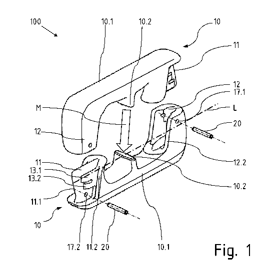
Figure 1 in a perspective exploded view shows a block lock 100 which is formed
from two half-elements 10. The half-elements 10 are preferably of identical
configuration. The arrow between the half-elements 10 identifies the assembly
direction M in which the upper half-element 10 is placed onto the lower half
Date Regue/Date Received 2020-12-10
CA 03103338 2020-12-10
WO 2019/242819
PCT/0E2019/100581
7
element 10, and the chain-dotted line identifies the position of a
longitudinal
axis L.
Each half-element 10 possesses a longitudinal web 10.1, one insertion plug 11
being configured at one end of said longitudinal web 10.1, wherein the width
of
said insertion plug 11 is significantly reduced in comparison to the other
portions. Two retaining webs 13.1, 13.2 of dissimilar lengths are configured
on
the lateral external flanks of the insertion plug 11. The insertion plug 11 is
delimited by a flank 11.2 which extends obliquely upward, specifically so as
to
be inclined in relation to the center. The end-proximal edge 11.1 of the
insertion
plug 11 however extends in each case from the external side obliquely outward
to a separation plane which runs through the longitudinal axis L, such that a
trapezoidal shape of the insertion plug 11 results in the lateral view.
A receptacle pocket 12 which is likewise delimited by an oblique flank 12.2 is
configured at the opposite end of the longitudinal web 10.1 of the half-
element
10, wherein the inclination of said flank 12.2 corresponds to the inclination
of
the flank 11.2 on the insertion plug 11. The receptacle pockets 12 and the
insertion plugs 11 form mutually complementary receptacle regions, that is to
say that recesses and grooves on the one side interact with protrusions and
webs on the respective mating piece.
A central web 10.2 which projects transversely from the longitudinal web 10.1
is configured between the insertion plug 11 and the receptacle pocket 12.
Moreover provided are bores 17, 18 into which safety pins 20 can be inserted
after the half-elements 10 have been joined.
Figure 2 shows a single half-element 10 in a perspective view so as to
highlight
in particular the design of the retaining webs 13.1, 13.2 in the insertion
plug 11,
and the associated retaining grooves 14.1, 14.2 in the receptacle pocket 12.
The webs 13.1, 13.2 and the grooves 14.1, 14.2 possess upper and lower
edges which are axially parallel and serve for transmitting force and in each
Date Recue/Date Received 2020-12-10
CA 03103338 2020-12-10
WO 2019/242819 PCT/0E2019/100581
8
case taper off so as to be radiused toward the end sides in order to
facilitate
the assembly.
Figure 3A in a lateral view shows a first assembly step. A chain link 1 which
is
held in a form-fitting manner on a hook-shaped protrusion 18 is placed into a
lower half-element 10 on the left. A further half-element 10 is depicted
thereabove. Said further half-element receives a second chain link 2 on the
right, the latter by way of a hook-shaped protrusion 18 being likewise already
guided and held in an early stage of the assembly. The vertical dashed lines
identify the position of that respective edge in the receptacle pocket 12 that
first
has to be passed by the longer retaining web 13.1 of the insertion plug 11.
Since the retaining grooves 14.1, 14.2 as well as the associated retaining
webs
13.1, 13.2 are radiused at the end sides, the initial position of the two half-
elements 10 illustrated in figure 3A is possible only by way of a very minor
mutual axial offset. On account thereof, a very short closing distance which
can
be completely covered within the respective eye of the connected chain links
1, 2 is implemented. Any later pivoting of the block lock 100 into the profile
of
the chain is thus not required.
The next assembly step in which the retaining elements are mutually converged
further such that the respective longer retaining webs 13.1 are positioned so
as
to be level with the respective shorter retaining grooves 14.2 is shown in
figure
3B.
Figure 3C shows this assembly step once again together with the adjacent
chain links 1, 2, 3, 4 in order to highlight that the distance available for
closing
the block lock is limited by virtue of the length and the design of the chain
links.
In this assembly intermediate step, both half-elements 10 by way of the
insertion plugs 11 and receptacle pockets 12 thereof are already positioned
completely within the eyes of the adjacent chain links 1, 2, wherein the chain
links can remain in the stretched profile of the chain and do not have to be
repositioned for assembling the block lock.
Date Regue/Date Received 2020-12-10
CA 03103338 2020-12-10
WO 2019/242819
PCT/0E2019/100581
9
Proceeding from the position according to figures 3B and 30, in order to
finally
join the half-elements 10, another final staircase-shaped movement is
performed in which the half-elements 10 are first pressed against one another
along the longitudinal extent of the part of the chain, are pressed apart so
as to
cancel again the temporary engagement of the long retaining webs 13.1 in the
short retaining grooves 13.2, and then pushed transversely such that the
position according to figure 3D is reached. Proceeding from the latter, the
half-
elements 10 are moved to the terminal position by a final advancing movement
in the longitudinal direction.
The terminal position is depicted in figure 4. The long retaining webs and
retaining grooves 14.1, 13.1 mutually engage as do the short retaining webs
and retaining grooves 14.2, 13.2. The central webs 10.2 bear on one another
such that two mutually separate eyes 31, 32 are configured. The ends of the
eyes 31, 32 are in each case formed by the radiused inner flanks 18 in the
shape of hooks. The inserted safety pins 20 secure the mutual position of the
half-elements 10.
Date Recue/Date Received 2020-12-10