Note: Descriptions are shown in the official language in which they were submitted.
CA 03104585 2020-12-21
Device and Method for Treating Fibres
Description
The invention relates to a device and a method for treating fibres, especially
cellulose, of a mixture
of substances containing fibres or cellulose, wherein only a sub-surface of a
second refining
surface of a movable treatment body is applied with the mixture of substances
in relation to a first
refining surface.
Fibres for the textile and especially paper industry must generally be treated
or processed for the
later use, so that the resulting product, such as paper, can have the desired
properties in terms of
strength, surface finish, printability and similar.
Most commonly, in the paper industry, one can find refining procedures that
use refining units,
especially refiners. The skilled persons are aware of a variety of possible
arrangements of refining
surfaces, between which the fibres of a mixture of substances or substances
are treated. The
refining surfaces are usually equipped with individual teeth, bars, rows of
teeth or similar, between
which grooves, notches or similar are provided. Such refining surfaces with
blades or even the
refining tools are often referred to as (refining) sets.
Usually, during the treatment, the mixture of substances is pressed between
the refining surfaces
and processed in a processing or treatment zone. Depending on the arrangement
of the refining
tools or refining surfaces, the processing zone is provided between a
unilaterally rotating refining
surface (e.g. rotor-stator arrangement of a single disc refiner) or between
refining surfaces rotating
against each other (e.g. double disc refiner). Even other refiners, such as
drum or conical refiners,
work according to this principle. In similar processes, such as dispersion, a
mixture of substances
containing fibres is applied on refining, processing or treatment surfaces.
The treatment or processing of the fibres takes place through pressure pulses
between the
extensions, such as blades, edges, etc. of the respective refining surfaces.
Whether the fibres are
cut more (crisp refining) or fibrillated more (greasy refining) during the
processing, depends on
some parameters known to the skilled person. As parameters, besides the
geometry of the refining
tools, the setting of the refining gap or of the treatment zone, the specific
edge load as defined by
Brecht-Siewert, the substance density used, even other factors can have an
influence on the
refining intensity of the mixture of substances used and the processed fibres,
respectively.
In order to ensure economical refining or dispersion with a high throughput of
the mixture of
substances, only such arrangements are so far known, in which the refining
surfaces and partly
1
Date Recue/Date Received 2020-12-21
CA 03104585 2020-12-21
even adjacent secondary surfaces are in direct contact with the mixture of
substances. This
means, using the example of a double disc refiner, as disclosed e.g. in
DE10066175B4, or even a
drum refiner, as disclosed e.g. in EP2659061B1, that a very high amount of
energy must be
expended for moving the rotating refining surfaces. In addition, most of the
known arrangements
require a pressure housing in order to ensure the supply of the mixture of
substances to be
processed into the treatment zone. In other words, it is necessary to apply
the mixture of
substances to the entire moving refining surface of both refining tools used
in the treatment
process. In most cases, the mixture of substances is also applied onto other
moving parts, such as
shafts; as a result, a part of the amount of energy used cannot be used for
the actual treatment of
the fibres. Moreover, known arrangements must often be equipped with complex
sealing solutions
in order to ensure a controllable supply and/or removal of the mixture of
substances. Furthermore,
known devices often have a very complicated design and cause relatively high
costs for
maintenance and service work, since the sets or refining tools used wear and
always require a
standstill for maintenance work.
Other refiner designs are also known to the skilled person under the term
"Hollander refiners",
wherein a non-pressurised drum-shaped refining surface is immersed in a
suspension containing
fibres. A continuous operation is however not possible, as a result of which
the throughput of the
processed mixture of substances remains very low.
The object of this invention is to overcome the disadvantages of the state of
the art and to provide
a device and a method, using which a user is able to carry out a simple, cost-
effective, reliable and
particularly energy-efficient treatment or processing of a mixture of
substances containing fibres.
Another object of the invention is to keep the total energy expenditure and
especially the idle
power during the operation of the device as low as possible. This invention
must furthermore
provide a device and a method, which is suitable for treating different
substance densities with only
slight adjustments and, among other things, shortens or cheapens the
maintenance work
significantly.
This object is achieved by a device and a method according to the claims.
The device according to the invention, especially a refiner, for treating
fibres of a mixture of
substances containing fibres, comprises at least one outlet element for the
passage of the mixture
of substances containing fibres having an outlet opening and at least one
first refining surface
arranged around the outlet opening in a circumferential direction, and at
least one feeding device
for positioning the outlet element In order to treate the mixture of
substances containing fibres, a
movable treatment body having a second refining surface is arranged opposite
the at least one
outlet element, wherein, with the passage of the mixture of substances
containing fibres through
2
Date Recue/Date Received 2020-12-21
CA 03104585 2020-12-21
the outlet element, a gap-type treatment zone is formed between the first
refining surface of the
outlet element and a sub-surface of the second refining surface of the movable
treatment body,
applied with the mixture of substances.
In the method according to the invention, at least the following process steps
performed:
- provision of a mixture of substances, which comprises at least one liquid
component, preferably
water, and fibres, preferably cellulose;
- moving of a movable treatment body relative to the at least one outlet
element with a pre-
definable relative speed;
- pressing of the mixture of substances containing fibres through the at least
one outlet element
with a pre-definable process pressure;
- treating of the mixture of substances by forming a gap-type treatment
zone for the treatment of
fibres between a first refining surface of the at least one outlet element and
a sub-surface of a
second refining surface of the movable treatment body, applied with the
mixture of substances, by
positioning the outlet element relative to the movable treatment body;
Due to the relative movement of the second refining surface of the treatment
body relative to the
outlet element or the first refining surface, the fibres of the mixture of
substances are treated or
processed in the gap-type treatment zone. In the context of this invention,
treatment is understood
as the fibrillation and/or shortening and/or increase of the binding capacity
of fibres and/or
dispersion, up to the generation of nano-fibres. The refining intensity can be
adjusted in this way.
Thereby, the intensity of the fibre treatment can be set relatively easily
through the working
distance or refining gap and/or the relative speed of the effective refining
surfaces or refining sets
with respect to one another and/or the design of the refining sets.
A significant advantage lies in the energy-efficient arrangement of the partly
known components,
especially in the application of only a sub-surface of the second refining
surface, which is arranged
on the movable treatment body. A significant reduction of the idle power can
be achieved through
application of, in comparison with known arrangements, relatively small parts
of the second refining
surface or the moving refining tool. Thus, the total energy expenditure for
the operation, particularly
drive of the treatment body, of the device can be significantly reduced as
compared to a refining
surface "fully" applied with a mixture of substances. For further explanation,
reference is made to
the exemplary, schematic representations of Fig. 1 a in comparison with the
embodiments
according to the invention and their discussion.
Moreover, a very gentle treatment of the fibres is possible due to the fact
that high rotational
speeds of the movable treatment body or relative speeds between the first and
second refining
surface can be adjusted, as a result of which the refining energy brought in
is relatively high in
comparison with the total energy expenditure.
3
Date Recue/Date Received 2020-12-21
CA 03104585 2020-12-21
The device according to the invention is suitable for treating a variety of
organic and/or synthetic
fibres, but preferably pulp or cellulose. The mixture of substances can be
supplied via at least one
supply device for providing the mixture of substances containing fibres at the
outlet element with a
pre-definable process pressure. The pre-definable process pressure generates a
continuous flow
of the mixture of substances in the treatment zone and can be used for
variation of a change in
speed of the mixture of substances in the treatment zone.
The presented device also allows removing long and/or not sufficiently chopped
or processed
fibres and/or other interfering material from the treatment zone through the
relative movement of
the treatment body and preventing clogging of the device. Thus, a relatively
high quantity of
mixture of substances can be processed and the homogeneity of the processed
mixture of
substances can also be increased. The process safety is also increased.
Furthermore, the refining surfaces used can be adjusted relatively easily to
the requirements of the
mixture of substances to be processed, as a result of which a function as a
disperser or as a
refiner can be realised with the same operating principle by means of the
device or method
according to the invention. It is therefore possible to process very different
substance densities
from 0.1 to 35 vol. % and partly, also up to 50 vol. %, while substance
densities of 2 to 35 vol. %
are customary in case of conventional dispersers or refiners. One of the
reasons for this is that the
removal of the mixture of substances in the treatment zone is not so strongly
dependent on the
groove geometry of the two corresponding refining surfaces, but is
substantially supported by the
relative movement of the second refining surface in relation to the first
refining surface. The design
of the supply device as a conventional fluid pump may not be sufficient under
certain
circumstances for very high substance densities and alternatively, for
example, a screw conveyor
or similar may be beneficial.
The first and/or second, or further, refining surface(s) can have teeth,
blades, or similarly
functioning extensions, which, if the device according to the invention is
designed as a disperser,
mesh with one another during the operation; while, if the device is designed
as a refiner, they are
moved past one another preferably as rows of blades.
Moreover, the device according to the invention can be manufactured and
operated in a relatively
easy and cost-effective manner, since complicated components are omitted. Any
wearing parts are
relatively easily accessible and affordable to replace, due to which the
operating times can be
increased significantly. In addition, the at least one outlet element can,
under certain
circumstances, be changed or replaced possibly even during the operation of
the device.
4
Date Recue/Date Received 2020-12-21
CA 03104585 2020-12-21
Since the processed mixture of substances is very highly accelerated when it
exits the treatment
zone, it can be easily collected in a housing surrounding at least parts of
the treatment body and/or
the outlet element A considerable part of the treatment body is thus not in
direct contact with the
mixture of substances. The treatment body can therefore be moved with low
resistance, as a result
of which the total power consumption can be significantly reduced by the
amount of the saved idle
power. This further implies that no pressure housing has to be used for the
supply/removal of the
mixture of substances, but a simple housing for collecting the substance is
sufficient.
Moreover, it can be expedient if the movable treatment body is designed such
that it can be driven
in a direction of movement in essence laterally, preferably orthogonally,
towards an outlet element
axis of the outlet element by means of a drive device.
This corresponds to an "active" and thus regulatable movement of the movable
treatment body in
the direction of movement The outlet element axis essentially corresponds to
an imaginary
longitudinal axis through the outlet element at the centre of the outlet
opening. The movement
takes place in essence laterally, preferably orthogonally, towards the outlet
element axis of the
outlet element and can be initiated and regulated by means of the drive
device. In this way, the
relative speed and thus the amount of the refining intensity in the treatment
zone can be adjusted
relatively easily.
As explained above, the so-called edge load in the refining surfaces, i.e. the
refining tools or
refining sets, and thus the degree of shortening of the fibres during the
refining can be effectively
influenced by means of the rotational speed of the treatment body or the
relative speed of the
second refining surface. The specific edge load according to Brecht-Siewert
represents a well-
known measurement for the refining intensity. The specific edge load is thus
to be understood as
an intensity parameter that indicates the amount of energy introduced into the
mixture of
substances over a certain blade/edge/groove length. The refining intensity
results from the quotient
of pure refining power and the edge length per second in Jim. The pure
refining power
corresponds to the difference between the total refining power and the pump
power or idle power.
The higher the edge load, the stronger the fibres are shortened; while a lower
edge load has an
intensified fibrillating effect The edge load can be reduced by increasing the
rotational speed and it
can be increased by reducing the rotational speed. Thus, according to the
invention, a pre-
definable quality of the processed fibres can be set in a relatively easy
manner. Accordingly, any
type of motor, such as electric or hydraulic motors, can be used as drive
device.
Provision can also be made for the movable treatment body to be designed as
rotationally
symmetrical, e.g. as a disc, cylinder, cone, or in the form of a band, e.g. a
chain or band.
Date Recue/Date Received 2020-12-21
CA 03104585 2020-12-21
The geometry of the treatment body can be selected by the skilled person in
view of the available
space, feeding rates, drive power and similar. In certain cases, band-shaped
treatment bodies can
therefore be advantageous, which are also only partly applied with the mixture
of substances. The
rotationally symmetrical treatment bodies also allow a relatively simple
design according to the task
and can be designed to be dimensionally very stable without having to accept
excessive energy
expenditure for the movement; because, in each case, only a sub-surface
applied with the
substances is sprayed with the mixture of substances.
It is also particularly beneficial that the movable treatment body is designed
to be rotatable as a
disc laterally, preferably orthogonally, towards the outlet element.
When embodied as a disc or plate, the advantages of inexpensive procurement,
long service life
and low maintenance costs can be used particularly well. Moreover, such discs
can have suitable
receptacles for separately arranged refining surfaces, as a result of which
only the worn refining
surface must be replaced if necessary.
Furthermore, it can be provided that the at least one feeding device is
designed to be movable
parallel to an axis of rotation of the disc, for setting a pre-definable
radial distance of the outlet
element axis from the axis of rotation.
This embodiment allows an independent or even additional possibility for
controlling the relative
speed in the treatment zone, which can be adjusted relatively easily using the
different
circumferential speeds depending on the radial distance from the axis of
rotation. This measure
can be provided in addition to or even instead of a rotational speed control
of the drive device and
offers another effective method for adjusting the refining intensity.
According to a further development, it is possible for at least the first
refining surface to have at
least one, preferably more than two, rows of blades.
For the execution of this invention, at least one first refining surface
"armoured with blades" or
edges is required. Under certain circumstances, the second refining surface
can have only a
multitude of teeth in order to apply the pressure surges onto the fibres of
the mixture of substances
during the treatment or processing. However, it has been found that a
particularly good treatment,
especially refining, can be achieved if both refining surfaces have a number
of rows of blades, as is
preferably the case in a device designed as a refiner.
Furthermore, it can be expedient if the at least one row of blades of the
first refining surface has a
6
Date Regue/Date Received 2020-12-21
CA 03104585 2020-12-21
closed refining edge.
By means of the closed refining edges, treating of the fibres can be improved
to the effect that, in
this way, the untreated outlet of the mixture of substances through any
notches, channels or
grooves can be controlled better or even completely avoided. This forcing of
pressure shocks
and/or refining edge contacts can contribute significantly to increasing the
refining efficiency, i.e. to
increasing the probability of the fibres being treated. By means of this
measure, the process
stability and quality of the processed fibres can also be increased.
Moreover, provision can be made for the first refining surface to have a
longitudinal extension,
which is larger in the direction of movement than in a transverse direction
and/or against the
direction of movement.
By optimising the shape of the first refining surface, homogenisation of the
outlet of the mixture of
substances along the circumference of the first refining surface can be
achieved. The homogeneity
and/or quality of the processed mixture of substances can also be improved in
this way, since the
refining intensity can be improved, or rather essentially become the same,
over the effective first
refining surface in all directions.
Furthermore, the at least one, preferably more than two, row(s) of blades of
the first refining
surface can be arranged concentrically in relation to the outlet opening.
Due to this measure, an uncontrolled outlet of the mixture of substances
through notches, grooves
or channels can be efficiently reduced, or even avoided. The rows of blades
can preferably have a
closed edge line, as a result of which this effect can be increased further.
This forcing of pressure
shocks and/or refining edge contacts can contribute significantly to
increasing the refining
efficiency.
According to a particular form, it is possible for the first refining surface
to be designed as being
substantially complementary in shape to the sub-surface of the second refining
surface of the
movable treatment body, which is applied with the mixture of substances.
In particular, in case of curved inner or outer surfaces of the treatment
body, e.g. in case of a
cylinder or a cone, this measure can increase the homogeneity of the outlet of
the mixture of
substances from the treatment zone, which is formed for the uneven sub-
surface, to which the
mixture of substances is applied. This can decisively contribute to
homogenising the local outlet
speeds and/or the refining intensity on the fibres to be processed in the
treatment zone via the first
refining surface, which contributes to increasing the quality.
7
Date Recue/Date Received 2020-12-21
CA 03104585 2020-12-21
According to an advantageous further development, it can be provided that an
end section of at
least one outlet element is designed to be rotatable, preferably drivable, at
least partly around the
outlet element axis.
With the help of a rotatable outlet element, for example by means of a
suitable design of the first
refining surface, a "passive" rotation of the first refining surface can be
effected during the passage
of the mixture of substances. The formation of a separately drivable, i.e.
rotatable, end section is
however considered to be advantageous. In both cases, the wear of the first
refining surface, which
develops primarily in the direction of movement of the movable treatment body,
can be
compensated step-by-step or even continuously with an "active" pre-definable
rotation. As a result,
uniform wear of the first refining surface can be achieved, thanks to which
the service life or
operating life can be increased. This can also be used to improve a
continuously uniform quality of
the processed mixture of substances.
In particular, it can be advantageous if the at least one feeding device is
designed such that it can
be aligned in order to set a working distance between the first refining
surface of the at least one
outlet element and the sub-surface of the second refining surface of the
movable treatment body,
which is applied with the mixture of substances.
This can take place independently or even in combination with other measures,
such as the setting
of the relative speed and/or the process pressure of the mixture of substances
and/or the setting of
a radial distance in case of a disc-shaped treatment body.
It may be particularly advantageous to regulate the relative speed of the
moving treatment body in
order to adjust the refining intensity formed in the gap-type treatment zone.
It can also be
advantageous that the working distance or refining gap between the at least
one outlet element
and the corresponding sub-surface applied with the mixture of substances is
regulated in order to
set pre-definable pressure forces on the moving treatment body by means of at
least the feeding
device. The first refining surface is not in direct contact with the second
refining surface. The
pressure forces, i.e. a contact pressure, can bring about targeted adjustment
of the working
distance and thus a defined treatment zone, since a "floating" and possibly
the formation of an
uncontrolled treatment zone could take place as a result of the local passage
of the mixture of
substances with the pre-definable process pressure. The outlet speed of the
processed mixture of
substances can thus be influenced, as a result of which the refining intensity
in the gap-type
treatment zone can be adjusted in a targeted manner.
Furthermore, provision can be made for at least two outlet elements to be
arranged symmetrically
8
Date Regue/Date Received 2020-12-21
CA 03104585 2020-12-21
in the circumferential direction and/or radial direction relative to the
movable treatment body.
Through the arrangement of several outlet elements, which each form a
treatment zone together
with a common treatment body, the throughput of the mixture of substances can
be significantly
increased. This is particularly advantageous, since, during ongoing operation,
one or several outlet
elements can be easily "switched on/off' as necessary and even maintenance
work of individual
outlet elements is possible. In addition, this measure can be used to reduce
or even completely
compensate for any bending moments that are applied onto the treatment body
through the
process pressure and/or the contact pressures. This enables a more stable and
low-maintenance
device.
Furthermore, it can be provided that at least one second outlet element is
arranged essentially
opposite to a first outlet element, whereby the first outlet element is
assigned to a second refining
surface of the movable treatment body and the respective corresponding second
outlet element is
assigned to a third refining surface opposite to the second refining surface.
Due to the formation of plural outlet elements, which each form a treatment
zone together with the
common treatment body, the throughput of the mixture of substances can also be
significantly
increased. Through the opposite arrangement of two corresponding outlet
elements, a reduction in
the bending moments, up to a complete compensation of the bending moments, on
e.g. the drive
axis of the treatment body or even the treatment body itself, can be brought
about This measure
can be advantageous in case of band-shaped treatment bodies as well as in case
of rotationally
symmetrical treatment bodies, e.g. a cylinder or a disc, as long as the sub-
surfaces of the
corresponding outlet elements applied with the mixture of substances
essentially lie opposite to the
second and third refining surfaces.
It can also be provided that at least two outlet elements are arranged along
the direction of
movement and/or essentially orthogonally in relation to the direction of
movement of the movable
treatment body.
It is also conceivable here for the outlet elements to be arranged staggered,
i.e. offset with one
another, in at least one direction. The arrangement of several outlet elements
allows for higher
productivity using only one common treatment body. This advantage is similar
to the formation of
the aforementioned outlet elements arranged opposite one another on second and
third refining
surfaces mainly in the fact that the power consumption for driving the movable
treatment body
increases only slightly or even negligibly. Thereby, a large quantity of the
mixture of substances
can be processed at the same time in a very energy-efficient and cost-
effective manner. It can thus
easily be imagined that several outlet elements can be arranged along a
cylinder or even a cone.
9
Date Recue/Date Received 2020-12-21
CA 03104585 2020-12-21
Here, the outlet elements can basically also be arranged opposite one another
on the second
refining surface, i.e. for example an outer surface of the cylinder; as a
result, the bending moments
on the drive axis of the treatment body can be compensated for. It is also
conceivable to arrange
the outlet elements in the circumferential direction of a disc, which causes
the same effect on the
disc.
An increase in the number of outlet elements can, in any case, bring about a
considerable increase
in the sub-surfaces, applied with the mixture of substances, on the total
surface of the second
and/or third refining surface, which, according to the invention, is
associated with a comparatively
low increase in the idle power.
Furthermore, several outlet elements can also be assigned to a common
adjustment device and/or
supply device, which results in a very favourable design.
A design, according to which it can be provided that at least the movable
treatment body of the
drive device is arranged with sealing from a housing, by means of at least one
contacting and/or
non-contact sealing element, preferably a maintenance-free labyrinth seal, is
also advantageous.
Complex sealing solutions can be dispensed with thanks to the relatively
simple design of the
device according to the invention. Although the mixture of substances is
treated with a process
pressure, the mixture of substances is, as a rule, only exposed to atmospheric
conditions after it
exits. In order to collect the processed mixture of substances, a housing is
advantageous, which
shields at least the sub-surfaces that are applied with the mixture of
substances, preferably the
entire treatment body, from the environment. In order to seal the housing
openings such as the
outlet elements or a drive shaft, e.g. simple contacting rubber seals can be
used, or even self-
sealing, maintenance-free labyrinth seals, as are known to the skilled person.
This enables
particularly long maintenance intervals and low production costs.
It has proven to be advantageous if a collecting container for collecting
and/or further processing
the processed mixture of substances is assigned to the housing. In certain
cases, an essentially
complete sealing of the housing can be advantageous in order to place the
treatment space under
low pressure or high pressure or also to form a protective gas atmosphere
therein, as a result of
which the quality of the processed mixture of substances can be influenced in
a targeted manner.
According to a further development, a chemical and/or enzymatic and/or
mechanical pre-treating of
the mixture of substances can be carried out prior to the provision of the
mixture of substances.
By means of a chemical and/or enzymatic pre-treating, the drying of the fibre
components can be
Date Regue/Date Received 2020-12-21
influenced in a targeted manner, as a result of which the treating, especially
shredding, of the fibres can
be facilitated. Such a pre-treatment can be carried out in an external device
or even in a section of the
supply device provided for this purpose. Likewise, a mechanical pre-treatment
is possible for setting a pre-
definable fibre length or distribution of the fibre lengths and/or diameters.
Such mechanical pre-treatments,
as well as sorting, sifting, etc. are sufficiently known to the skilled
person. A suitable pre-treatment can thus
be used for increasing the quality of the processed mixture of substances and
integrated into the method
according to the invention.
Furthermore, it can be expedient if at least the method steps of pressing
through and processing are
repeated with at least parts of the processed mixture of substances.
The quality and homogeneity of the processed mixture of substances can be
increased through repeated
treatment of the mixture of substances containing fibres. It is conceivable
here to re-feed at least parts, or
even the entire quantity, of the processed mixture of substances of a passage
to the device. In this case,
a circulation system betw een the collecting container and the supply device
can be used very easily to
achieve a pre-definable fibre diameter and/or length distribution. In certain
cases, it rrey be advantageous
to adjust the liquid corrponent of the processed and re- supplied mixture of
substances by e.g. adding
water. A particularly fine pulping of the fibre components can be achieved
here with relatively low energy
and/or pressure expenditure.
The device or method according to the invention can use one or several sensors
for detecting, controlling
and monitoring at least parts of the device and of the method. Such sensors
are known to the skilled person
and are therefore not explained in detail.
For a better understanding of the invention, the same will be explained in
more detail based on the following
figures.
It is shown in each case in a highly simplified, schematic representation:
Fig. la is a schematic sectional view of a device for the treatment of fibres
according to the state of the art;
F. lb is a schemlic sectiond VeN of an exarrple of an arrangement according to
the invention;
Fig. 2 is a schematic cross-sectional view of an outlet element and a
treatment body with respective refining
surfaces for explanation of the operating principle;
Fig. 3a is a schematic cross-sectional view of an embodiment of a device with
two outlet elements, which
are arranged in a distributed manner in the circumferential direction on a
second refining surface;
F. 3b ea schematic cross-seclional view of an errbodiment of adevice with two
outlet elements, which are arranged
opposite one another on a second and third refining surface;
Fig. 4a is a schematic cross-sectional view of an embodiment of treatment
bodies as cylinder with several
outlet elements;
11
Date Recue/Date Received 2022-07-04
Fig. 4b is a schematic cross-sectional view of an embodiment of treatment
bodies as cone with several
outlet elements;
Fig. 4c is a scherretic cross-sectional view of an errbodiment of treatment
bodies as band with several
outlet elements;
Fig. 5a is a schematic representation of an errbodi me nt of ai outlet element
with a first ref ining surface with
a larger extension in the direction of movement;
Fig. 5b is a schematic representation, in a bottom view, of an embodiment of
an outlet element with
concentrically arranged rows of blades;
9g. 5c S a schematic representation, ri a bcitom vew , with a first refining
surface complementary to the shape;
Fig. 6 is a schematic cross-sectional representation of a possible embodiment
of an outlet element with a
rotatable end section;
Fig. 7 is a schematic overview representation of a possible arrangement of a
device for treating fibres.
It should be noted introductorily that, in the differently described
errbodirrents, identical parts are provided with
identical reference syn-bols or identical component designations, w hereby the
disclosures contained in the
entire description can be transferred analogously to identical parts with
identical reference symbols or
identical component designations. Even the position indications selected in
the description, e.g. top, bottom,
lateral, etc., refer to the figure directly described and illustrated and, in
case of a change in position, these
position indications should be analogously transferred to the new position.
Fig. la is a scherretic illustration of a double-disc refiner according to the
state of the art. This illustration
helps to explain the operating principle of conventional, known treatment
devices, in which a very high
amount of energy must be applied for moving the rotating refining surfaces or
sets. In the selected
representation, the mixture of substances 2 is supplied via a substance
mixture supply 32 in a pressure
housing 33. The movably and rotatably, respectively, arranged rotor 34 forrrs
a treatment zone 16 with the
stators 35 on both sides, w hich extends over the entire rotor surface and the
respective stator surfaces.
The movement of the mixture of substances 2 used is indicated schematically
using movement arrows.
The surfaces 36, which are applied with the mixture of substances, are show n
by dotted lines for better
illustration. As can be seen very clearly from this representation, it is
necessary to apply the mixture of
substances to the entire moving surface 36 of both refining tools used in the
treatment process, i.e. the
rotor 34 and the stators 35. Normally, the refining tools used are very
expensive and partly complicated. In
addition, the shaft of the rotor 34, as well as secondary surfaces that are
not effective in the treatment
process, such as the lateral or outer surfaces of the rotor and the stators,
are fully applied with the
12
Date Recue/Date Received 2022-07-04
CA 03104585 2020-12-21
mixture of substances 2, i.e. also with the process pressure in the pressure
housing 33. This
causes a very high power consumption and required idle power, respectively, of
the known device.
This also applies analogously for surfaces of refiners with a drum or cone
arrangement, which are
fully applied with the mixture of substances and which are not shown here.
After the treatment or processing of the mixture of substances 2 in a known
device, as shown in
Fig. la, the processed mixture of substances or fibres 5 exits through a
mixture of substances
outlet opening 37. Up to the mixture of substances outlet opening 37, the
mixture of substances 2
or the processed mixture of substances 5 is usually exposed to the process
pressure 15, which is
why sealing elements 30, which are not shown in detail, but are partly very
complex, must be
provided for sealing the pressure housing 33.
According to the invention, the application of a mixture of substances 2 to a
treatment body 7 takes
place only on sub-surfaces 10 of a second refining surface 9, which are
applied with the mixture of
substances, as shown e.g. in Fig. lb. In size and/or shape, these sub-surfaces
10 of a second
refining surface 9, which are applied with the mixture of substances,
essentially match with the
corresponding first refining surfaces 8. As can be seen in Fig. lb, for the
treatment of the fibres 3
containing mixture of substances 2, a common movable treatment body 7 with a
second refining
surface 9 is arranged opposite in relation to the at least one outlet element
11. In the selected
execution example, two outlet elements 11 are arranged symmetrically spaced-
apart in the radial
direction from the axis of rotation 24 of the treatment body 7 designed as
disc 22. When the
mixture of substances 2 containing fibres 3 exits through the two outlet
elements 11, a gap-type
treatment zone 16 is formed in each case between the first refining surface 8
of the outlet element
11 and the sub-surface 10 of the second refining surface 9 of the movable
treatment body 7, which
is applied with the mixture of substances.
Through comparison of Fig. 1 a and 1 b, the concept according to the invention
can be carried out
relatively easily, whereby, according to the invention, only small parts of
the total surface of the
treatment body 7, i.e. only the sub-surfaces 10 of the second refining surface
9, are applied with
the mixture of substances. The circular segment surfaces on the second
refining surface 9, which
are bordered with a dashed line, indicate that part of the processed mixture
of substances or of the
processed fibres 5 can be "taken along".
However, in comparison with the state of the art, this causes only a
negligible proportion of the
power consumption of the device 1, since the idle power of the device 1
according to the invention
accelerates only a small part of the treated mixture of substances 5 on the
second refining surface
9, which is anyway transported away in the direction of the housing 28 due to
centrifugal forces.
13
Date Recue/Date Received 2020-12-21
CA 03104585 2020-12-21
The at least one outlet element 11 for the passage of the mixture of
substances 2 containing fibres
has, in each case, one outlet opening 12 and at least one first refining
surface 8 arranged around
the outlet opening 12 in a circumferential direction. In the selected
representation of the operating
principle, the representation of possible feeding devices 18, supply devices
19, drive devices 20,
etc. in Fig. lb is dispensed with for the sake of simplicity. Reference is
made to the discussion of
Fig. 2 to Fig. 7 for the description of the mode of operation and possible
arrangements of the said
elements.
To illustrate the processes in the treatment of fibres 3 in the treatment zone
16, reference is made
to the schematic representation of Fig. 2. The movable treatment body 7 is
arranged opposite to
the at least one outlet element 11, as a result of which a gap-type treatment
zone 16 is formed
between the outlet element 11 or the first refining surface 8 and the sub-
surface 10 of the second
refining surface 9 of the movable treatment body 7, which is applied with the
mixture of substances
2.
As shown schematically in Fig. 2, the mixture of substances 2 comprises a
liquid component and
fibres 3, which can particularly consist of pulp 4 or cellulose. The mixture
of substances 2 is
pressed through the outlet element 11 with a pre-definable process pressure
15. The movable
treatment body 7 can, for example, be "passively" put into a relative movement
in a direction of
movement 23 through the outlet of the processed mixture of substances or of
the treated fibres 5
from the treatment zone 16. The treatment body 7 can also be moved "actively"
in the direction of
movement 23 by means of a drive device 20, e.g. as shown in Fig. 3 or Fig. 7.
When the fibres 3
containing mixture of substances 2 passes through the outlet element 11, the
fibres 3 are primarily
treated with pressure shocks in the gap-type treatment zone 16 formed in the
gap-type manner.
These pressure shocks on the fibres 3 are caused through the relative movement
of the first and
second refining surface 8, 9, especially through the teeth, blades, rows of
blades 26 arranged on
the respective refining surfaces or similar identically functioning elements.
As can very well be seen from Fig. 2 in connection with Fig. 1, as well as
Fig. 4 to Fig. 6, the
relative movement of the treatment body 7 is used to avoid clogging of any
notches 29 of the first
and/or further refining surfaces 8,9,13.
The exemplary embodiment in Fig. lb illustrates a treatment body 7 designed as
disc 22. In this
case, the treatment body 7 is rotatable around an axis of rotation 24 or
movable. The outlet
element 11 has an outlet element axis 21, which essentially corresponds to an
imaginary
longitudinal axis through the outlet element 11 at the centre of the outlet
opening 12. As can be
seen especially well from Fig. 2 in connection with Fig. lb and/or Fig. 3 and
Fig. 7, the relative
speed 27 in the treatment zone 16 can be set mainly using the radial distance
25 between the
14
Date Recue/Date Received 2020-12-21
CA 03104585 2020-12-21
outlet element axis 21 and the axis of rotation 24.
It can be seen from the combined view of Fig. 2 and Fig. lb, Fig. 3 to Fig. 7
that the movable
treatment body 7 goes past the outlet element 11 in a movement direction 23.
This relative
movement takes place preferably and essentially in a lateral way, especially
orthogonally towards
an outlet element axis 21.
An exemplary design of a feeding device 18 for positioning the outlet element
11 is illustrated in
Figs. 3, 4 and Fig. 7 and can be accordingly transferred onto Figs. 1 b, 2 and
5. As can especially
be seen from Fig. 3a and b, the feeding device 18 can be used to move the at
least one outlet
element 11 in the direction of the treatment body 7 and/or transversely in
relation to it. Such a
feeding device 18 can particularly be used to set the working distance 17.
Fig. 3a to 3c schematically represent devices 1, in which two or more outlet
elements 11 are
arranged in relation to a treatment body 7. Fig. 3a represents two outlet
elements 11, which are
arranged on a second refining surface 8 of the treatment body 7 symmetrically
spaced-apart from
the axis of rotation 24. Fig. 3b schematically represents a situation, where
two outlet elements 11
are arranged essentially opposite and symmetrical to each other on a second
refining surface 8, or
a third refining surface 9, of the treatment body 7. In the embodiments
represented in Fig. 3a and
b, any bending moments on the disc 22 and thus on the axis of rotation 24 can
be compensated for
by designing the treatment body 7 as disc 22.
The supply of the at least one outlet element 11 can, in each case, be
achieved via a separate
supply device 19 or even via a common supply device 19 for provision of the
fibres 3-containing
mixture of substances 2. The representation of such supply devices 19 in Fig.
1, Fig. 2, Fig. 4 and
Fig. 5 is dispensed with for the sake of simplicity.
The movable treatment body 7 can, according to the invention, be designed as a
rotationally
symmetrical body, e.g. as a cylinder or a drum or a cone or a disc 22, as
represented in Fig. lb to
Fig. 3 and Fig. 4a, 4b or Fig. 7. Alternatively, it is possible to design the
movable treatment body 7
as a band, e.g. as a chain or a band, as can be seen schematically from Fig.
4c. It can be seen
particularly from Fig. 3 and 4 that several outlet elements 11 can be assigned
to a commonly used
treatment body 7. The movable treatment body 7 can be connected with a drive
device 20, as can
be seen from Fig. 3, 4 and 7. Such a drive device 20 can be designed e.g. as a
hydraulic or
pneumatic motor and especially preferably as an electric motor and can have
speed control.
The feeding device 18 schematically represented in Figs. 3, 4 and 7 can be
designed such that it
Date Regue/Date Received 2020-12-21
CA 03104585 2020-12-21
can be aligned or positioned for setting a working distance 17 between the at
least one outlet ele-
ment 11 and the sub-surface 10 of the second or third refining surface 9,13 of
the movable
treatment body 7, which is applied with the mixture of substances 2. By means
of such a feeding
device 18, possibly the radial distance 25 of an outlet element 11 from the
axis of rotation 24 of a
treatment body 7 designed as a disc 22 can also be set, as can be seen
particularly well in the
overview of Fig. 1b, Fig. 2 and Fig. 7. It is also imaginable that several
outlet elements 11 can be
positioned together in relation to the treatment body 7 by means of a common
feeding device 18. It
can also be seen from Figs. 3 and 4 that at least two outlet elements 11 can
be arranged in the
circumferential direction and/or radial direction and/or longitudinal
direction in relation to the
movable treatment body 7. The outlet elements 11 can thereby be arranged
symmetrically and/or
offset with one another on a second refining surface 8 and/or third refining
surface 9.
A special embodiment in cylinders, cones, bands or chains has not been
illustrated, in which at
least a second outlet element 11 is arranged essentially opposite to a first
outlet element 11,
whereby the first outlet element 11 or the first refining surface 8 of a
second refining surface 9 of
the movable treatment body 7 and the corresponding second outlet element 11 is
arranged on a
third refining surface 13 opposite to the second refining surface 9. For a
treatment body 7 designed
as a disc 22, this situation can be seen from Fig. 3b and can be extrapolated
by the skilled person
onto other rotationally symmetrical and/or band-shaped treatment body 7.
In Figs. 5a to c and Fig. 6 several outlet elements 11 in different possible
embodiments are shown.
Fig. 5a schematically shows a bottom view of an outlet element 11 with a first
refining surface 8,
which has a larger longitudinal extension in the direction of movement 23 than
in the diagonal
and/or transverse direction. The arrangement of blades, spikes or other
extensions on the first
refining surface 8 can be selected by the skilled person depending on the
desired application, e.g.
as disperser or refiner. Similarly, this is also applicable for the second
and/or third refining surface
9,13, which are not represented separately. The represented exemplary
execution shows several
rows of blades 26 surrounding the outlet opening 12 and distributed outwards,
which are spaced
apart from one another using notches 29. When such first refining surfaces 8
are used, their shape
can be optimised by the skilled person according to the respective application
and geometry of the
treatment body 7. The treatment zone 16 should, as explained above, be formed
essentially
between the first refining surface 8 and the corresponding sub-surface 10 of
the second refining
surface 9, which is applied with the mixture of substances.
Fig. 5b shows a similar embodiment of an outlet element 11 with a first
refining surface 8 in the
bottom view, where the rows of blades 26 each have continuous and thus closed
refining edge. A
concentric arrangement of the rows of blades 26, spaced apart from each other
using notches 29,
16
Date Recue/Date Received 2020-12-21
CA 03104585 2020-12-21
can also be seen in the selected representation.
As can very well be seen from Figs. 5a and 5b, homogenisation of the mixture
of substances outlet
6 along the circumference of the first refining surface 8 can be achieved
through the suitable
design of the first refining surface 8, especially through its geometry and/or
arrangement of blades.
The outlet 6 of the mixture of substances is indicated with motion arrows.
Fig. 5c shows a schematic sectional view through an outlet element 11, a first
refining surface 8
surrounding the outlet opening 12 as well as a curved treatment body 7. The
first refining surface 8
is designed as being essentially complementary in shape to the sub-surface 10
of the treatment
body 7 or of the second refining surface 9, which is applied with the mixture
of substances 2. Here,
especially concave and convex shapes of the first refining surface 8 can be
imagined, as can be
seen particularly well in Fig. 5c.
Fig. 6 shows a schematic sectional view of another possible embodiment of an
outlet element 11,
whereby the outlet element 11 has a rotatable end section 14. This end section
14 can be
designed as being easily replaceable for easier maintenance. Likewise, such an
end section 14
can be "passively" or "actively" rotatable, whereby the "active" rotation can
be carried out by means
of a rotation device that is not shown. It is easily comprehensible from Fig.
6 that any wear of the
first refining surface 8, especially in the direction of movement 23, can be
homogenised through
the incremental and/or continuous rotation of the end section 14 over the
circumference of the first
refining surface 8.
According to the invention, the outlet elements 11 shown in Figs. 5a to 5c and
Fig. 6 as well as
their discussions can be included in the description of Figs. lb, 2, 3, 4 and
7. Likewise, their
combination within the scope of this invention has not been discussed
separately for the sake of
brevity, but reference is made to the corresponding discussions.
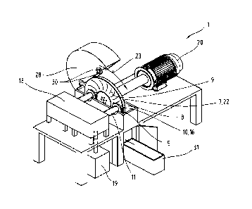
Fig. 7 shows a schematic overview of the device 1 according to the invention.
Here, two outlet
elements 11 are arranged in relation to the movable treatment body 7.
Positioning of the respective
outlet element 11 is performed by means of a feeding device 18. The supply of
the mixture of
substances 2 takes place via a supply device 19. The treatment body 7 designed
as a disc 22 is
driven by a drive device 20 in a direction of movement 23.
As can be seen from Fig. 7, the device 1 has a housing 28, which is shown in
an opened state.
The housing 28 primarily serves for collecting the substances during the
treatment and can be
sealed at least against the drive device 20 using one or several sealing
elements 30. Such sealing
elements 30 are, for example, also shown in Fig. 3 and can be designed as
contacting or even
17
Date Recue/Date Received 2020-12-21
CA 03104585 2020-12-21
non-contact sealing elements. The processed mixture of substances or the
processed fibres 5 can
be collected in a collecting container 31. It is also conceivable that the
supply device 19 is
connected with the collecting container 31 in order to implement a circulation
principle.
Within the scope of this invention, the individual method steps can also be
automated and
preferably controlled via a central, not shown system control. Moreover, the
operation is
contemplated on an operating panel or even a touch screen for the monitoring
and control of the
device 1.
The setting of a pre-definable distribution of fibre lengths and/or fibre
cross-sections and/or their
distribution can thus be defined by the user and regulated using a system
control. The repeated
passage of at least parts of the process mixture of substances 5 can also be
used to set the
homogeneity and/or quality of the processed fibres 5.
The substance density of the mixture of substances 2 can influence the quality
of the processed
mixture of substances 5. Suspensions, i.e. mixtures of substances 2, with a
fibre proportion of 0.1
to approx. 35 vol. %, preferably 1 to approx. 20 vol. %, can be processed
safely and easily with this
device 1 and the corresponding method. Substance densities of up to 50 vol. %
and above are
also imaginable. Under certain circumstances, it may be necessary for the
skilled person to fall
back on suitable supply devices 19, which are able to forward mixtures of
substances 2 with such
high substance densities. For example, feed screw arrangements are
particularly suited for this.
The embodiments show possible embodied variants, whereby it should be noted at
this point that
the invention is not limited to the specifically represented execution
variants of the same, but
various combinations of the individual embodied variants among themselves are
also possible and
this variation possibility lies in the ability of the skilled person working
in this technical field based
on the technical teaching of this invention.
The scope of protection is determined by the claims. The description and the
drawings should
however be used for interpreting the claims. Individual features or
combinations of features from
the different represented and described execution examples can, in their own
right, represent
independent inventive solutions. The task underlying the independent inventive
solutions can be
found in the description.
All specifications about value ranges in this description should be understood
such that these
include any and all sub-ranges thereof, e.g. the specification 1 to 10 should
be understood such
that all sub-ranges, starting from the lower limit 1 and the upper limit 10
are included, i.e. all sub-
ranges start with a lower limit of 1 or larger and end with an upper limit of
10 or lower, e.g. Ito 1.7,
18
Date Recue/Date Received 2020-12-21
CA 03104585 2020-12-21
or 3.2 to 8.1, or 5.5 to 10.
For the sake of good order, it is finally pointed out that elements have
partly been represented not
to scale and/or in a scaled-up and/or a scaled-down form for a better
understanding of the
structure.
19
Date Recue/Date Received 2020-12-21
CA 03104585 2020-12-21
List of reference signs
1 Device 29 Notch
2 Mixture of substances 30 Sealing element
3 Fibre 31 Collecting container
4 Cellulose 32 Substance mixture supply
Processed mixture of substances / 33 Pressure housing
fibres
34 Rotor
6 Mixture of substances outlet 35 Stator
7 Treatment body 36 Surface / secondary surface applied
with the mixture of substances
8 First refining surface according to the state of the art
9 Second refining surface
Sub-surface applied with mixture of 37 Mixture of substances outlet
opening
substances
11 Outlet element
12 Outlet opening
13 Third refining surface
14 End section
Process pressure
16 Treatment zone
17 Working distance
18 Feeding device
19 Supply device
Drive device
21 Outlet element axis
22 Disc
23 Direction of movement
24 Axis of rotation
Radial distance
26 Row of blades
27 Relative speed
28 Housing
Date Recue/Date Received 2020-12-21