Note: Descriptions are shown in the official language in which they were submitted.
CA 02721777 2010-11-18
EARTH GROUND TESTER WITH REMOTE CONTROL
Field of the Invention
[0001] The present invention relates generally to a facilitated method and
apparatus for
performing multiple ground resistance and soil resistivity measurements.
Background of the invention
[0002] A lack of good grounding is undesirable and increases the risk of
equipment
failure. The absence of an effective grounding system can lead to various
problems, such
as instrumentation errors, harmonic distortion issues, power factor problems
and a host of
possible intermittent dilemmas. If fault currents have no path to the ground
through a
properly designed and maintained grounding system, they will find unintended
paths.
Furthermore, a good grounding system is also used to prevent damage to
industrial plants
and equipment and is therefore necessary in order to improve the reliability
of equipment
and reduce the likelihood of damage due to lightning or fault currents.
[0003] Over time, corrosive soils with high moisture content, high salt
content, and high
temperatures can degrade ground rods and their connections. So although the
grounding
system may have had low earth ground resistance values when initially
installed, the
resistance of the grounding system can increase if the ground rods, or other
elements of a
grounding system, corrode over time. Grounding testers are useful
troubleshooting tools
in dealing with such issues as intermittent electrical problems, which could
be related to
poor grounding or poor power quality. It is therefore desirable that all
grounds and
ground connections are checked on a regular basis.
[0004] During these periodic checks, if an increase in resistance of more
than 20% is
measured, investigation of the source of the problem is undertaken so that
corrections
may be made to lower the resistance (e.g., by replacing or adding ground rods
to the
ground system). Such periodic checks may involve conducting established
techniques
such as fall-of-potential tests, selective measurements, soil resistivity
tests which may
also form part of a geological survey, two-pole measurements and stakeless
measurements. With present grounding test systems, in order to achieve
accurate results,
such tests tend to be extremely time consuming and labor intensive. In
particular when
dealing with measurements involving high voltage applications such as
electricity pylons,
the tests need to be conducted with caution.
1
CA 02721777 2010-11-18
[0005] According to the prior art, all the aforementioned grounding test
procedures
require a considerable amount of effort walking back and forth several times
between the
various electrodes connected to a testing device to ensure accuracy and/or
perform
multiple measurements. Specifically, once a testing device has been set up for
implementing the aforementioned techniques according to the prior art,
incorrect or
anomalous results can occur due to inadequate contact between the electrodes
and test
device due to loose clips, insufficient conduction or unsuitable placement of
the
electrodes. Hence, it is generally necessary to adjust the set-up and repeat
measurements
in order to correct such results. For example, an operator may check all
connections at
the various electrodes, which are often placed at large distances from one
another.
[0006] Performing this repeat measurement/correction procedure with a
single operator
tends to be extremely time-consuming and labor-intensive. In order to reduce
the wasted
time and effort associated with this procedure, a common solution to this
problem is to
provide more than one operator to conduct a single test procedure; however
this is often
not realistic or possible due to the availability of such further personnel.
Furthermore,
this solution is neither efficient nor convenient and incurs considerable
extra costs.
Summary of the Invention
[0007] The present invention recognizes and addresses the foregoing
considerations, and
others, of the prior art.
[0008] According to one aspect, the present invention provides a testing
device which
may be used to conduct any of the aforementioned techniques. The testing
device
comprises both a main unit and a remote unit adapted to communicate with one
another
via a communication link. After setting the testing device up according to the
desired
measurement technique, the respective procedure may be carried out, and the
resulting
measurement values are subsequently displayed on the remote unit. This allows
a single
operator to perform measurements while standing directly adjacent to an
electrode, which
is, for example, placed at a large distance from the main unit and/or other
electrodes.
This relieves the operator from constantly having to walk back and forth
placing
electrodes in different positions, and also obviates the need to return to the
main unit of
the testing device to consult a display and/or change parameters or settings.
2
CA 02721777 2010-11-18
[0009] With respect to fall-of-potential measurements, selective
measurements and two-
pole measurements, in order to achieve appropriate levels of accuracy when
performing
earth ground measurements, it is desirable that the respective resistances of
the auxiliary
electrodes are not too high compared to the resistance of the earth ground rod
being
tested. In geologically difficult conditions wherein high contact resistances
between the
electrode and the earth exist, exemplary embodiments enable the operator to
observe this
resistance displayed on the remote unit and take appropriate countermeasures
should the
value be too high. Such countermeasures may include tamping down the soil
around the
electrode or pouring water around the electrodes in order to improve contact
at the
soil/electrode interface. Thereafter, the operator can easily repeat the
measurements in
order to assess the success of the implemented countermeasures, without having
to move
location. Hence, this embodiment advantageously increases the efficiency of
performing
such measurements by eliminating a considerable amount of time and effort,
which
would normally be expended by at least one operator (and possibly several)
walking back
and forth between all three of the electrodes.
[0010] According to exemplary embodiments, the remote unit of the testing
device
preferably includes a display to indicate the measurement result in addition
to a control
means for performing different tests and measurements. Said control means may
for
example be used to set parameters, to start the test and to store the result,
etc. The remote
unit of the testing device may then transmit the respective commands to the
main unit,
which generates a predetermined current between the respective electrodes and
performs
the relevant measurements. Upon completing the measurement, the main unit may
transmit the measurement result to the remote unit of the testing device.
[0011] In one embodiment, the communication (i.e., transmission of
commands,
parameters and results) may be performed using a cable communication link
between the
main and remote unit. For example, embodiments are contemplated in which
existing
electrode test leads connected to the main unit may be utilized in order to
communicate to
and from the remote unit.
[0012] In a preferred embodiment of the present invention, however, such
communication between the main and remote units of the testing device occurs
wirelessly. This obviates the need for cumbersome wires, thus saving expense
and
3
CA 02721777 2010-11-18
reducing the steps required in setting up the testing device for use. Such
wireless
communication preferably occurs via a radio frequency (RF) link. For example,
Bluetooth, ZigBee, WLAN, mobile phone frequencies or other suitable RF link
may be
used for this purpose. In an alternative embodiment, the wireless
communication may
occur by infrared technology.
[0013] In a further embodiment, the main unit of the testing device may
comprise its own
display in addition to control means so that it may operate without the remote
unit. This
embodiment advantageously provides a back up system, should the remote unit
become
inoperable. However, in another embodiment of the present invention, the main
unit
could also merely comprise a "black box," which effectively requires the
remote unit to
operate it. A testing device according to this embodiment requires less
components and
thus achieves a reduction in manufacturing costs.
[0014] In yet another embodiment, the remote unit preferably comprises
a handheld and
portable device, which may be removably coupled with the main unit
mechanically
ancUor electrically. Fig. 6 shows an example of such a remote unit according
to this
embodiment of the present invention, wherein the main unit acts as a dock for
the remote
unit. This embodiment allows convenient transportation of the testing device
between
measurement sites.
[0015] In yet a further embodiment of the present invention, the
testing device,
preferably the remote unit thereof, may be equipped with a GPS receiver, which
enables
position and distance information to be captured and used for further
analysis. The GPS
receiver may also be used to obtain absolute coordinates including
geographical location
and distance information in three dimensions (i.e., including altitude). Thus,
the GPS
receiver may enable the literal mapping and location of the tests conducted
and the
respective distances involved (e.g., the respective locations of the remote
probes during
soil resistivity measurements). According to another embodiment, these
coordinates may
be stored in a database of sites that have been tested, wherein said data
could be used for
reporting, logging and preventative maintenance purposes. This is
especially
advantageous when applied to, for example, earth ground testing or geological
surveys,
since it is often necessary to measure a particular resistance, which is
related to a
respective distance. Furthermore, the inclusion of such a GPS receiver may
also improve
4
CA 02721777 2010-11-18
and facilitate the gathering of data for the purposes of obtaining a more
accurate, or
complete fall-of-potential curve, or geological surveys.
[0016] In an alternative embodiment, light (e.g., laser) or ultrasonic
distance
measurement means may be integrated in preferably the remote unit of the
testing device
in order to facilitate the determination of distance data. By incorporating
such distance
measurement means, the need to perform time-consuming and potentially
inaccurate
manual measurements is advantageously obviated.
[0017] In a further embodiment, either or both of the main and remote units
may
comprise memory storage and processing circuitry for storage and processing of
all
determined and measured values including, for example, distances, GPS
coordinates, date
and time, as well as standard test parameters. This offers the advantage that
a full record
of all measurements taken over a given time period or of a particular
grounding system or
area may be obtained which may, for example, be used for facilitated data
comparison
after the final measurement has been made.
Brief Description of the Drawings
[0018] A full and enabling disclosure of the present invention, including
the best mode
thereof, to one of ordinary skill in the art, is set forth more particularly
in the remainder
of the specification, including reference to the accompanying drawings, in
which:
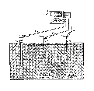
[0019] Fig. 1 shows a testing device for conducting a 3-pole fall-of-
potential test
according to the 62% rule according to one embodiment of the present
invention;
[0020] Fig. 2a shows a testing device for performing selective
measurements;
[0021] Fig. 2b shows a testing device for performing selective measurements
on a
plurality of ground rods according to an embodiment of the present invention;
[0022] Fig. 3a shows a testing device for measuring soil resistivity with 4-
pole tests;
[0023] Fig. 3b shows a testing device for conducting a geological survey
using 4-pole
tests according to yet another embodiment of the present invention;
[0024] Fig. 4 shows a method for performing two-pole measurements according
to the
present invention;
[0025] Fig. 5a shows a testing device connected to a grounding electrode to
be measured
via two clamps, for performing stakeless measurements of a ground electrode
according
to the present invention;
CA 02721777 2010-11-18
[0026] Fig. 5b shows a testing device for performing stakeless measurements
of a ground
electrode according to the present invention;
[0027] Fig. 5c is an equivalent circuit diagram showing the parallel
resistances of a
grounding system upon which stakeless measurements are performed according to
the
present invention;
[0028] Fig. 5d shows a testing device for performing stakeless measurements
on a
plurality of ground rods according to an embodiment of the present invention;
and
[0029] Fig. 6 shows a testing device for performing measurements comprising
a
coupleable main unit and remote unit according to the present invention.
[0030] Repeat use of reference characters in the present specification and
drawings is
intended to represent same or analogous features or elements of the invention.
Detailed Description of Preferred Embodiments
[0031] It is to be understood by one of ordinary skill in the art that the
present discussion
is a description of exemplary embodiments only, and is not intended as
limiting the
broader aspects of the present invention, which broader aspects are embodied
in the
exemplary constructions.
Fall-of Potential Measurement
[0032] As described above, one known method of measuring the ability of an
earth
ground system or an individual electrode to dissipate energy from a site is
the so-called
"fall-of-potential" test.
[0033] In one example of this test implemented according to the present
invention, an
earth electrode or ground rod to be tested is disconnected from its connection
to the
grounding system to avoid obtaining incorrect (i.e., too low) earth resistance
measurements caused by parallel grounding. The main unit of the testing device
is then
connected to the earth electrode X, which may then be used as a first current
electrode X.
One technique of performing a fall-of-potential test is three-point or 3-pole
testing, as
illustrated in Fig. 1. For the 3-pole fall-of-potential test, two further
(auxiliary) electrodes
Y and Z are provided (generally in the form of respective earth stakes),
wherein one of
the electrodes Z is placed in the soil at a predetermined distance away from
the earth
electrode X in order to be used as a second current electrode Z. The other
auxiliary
electrode Y is subsequently placed in the soil, for example, along a direct
line between
6
CA 02721777 2010-11-18
the earth electrode X and current electrode Z in order to be used as a voltage
probe Y.
Another common measurement topology (not shown) comprises placing the
electrodes at
a different angle to one another (e.g., 90 degrees). The two auxiliary
electrodes Y and Z
are also connected to the testing device.
[0034] In a next step according to this example, the main unit MU of the
testing device T
can generate a predetermined (known) current between the current electrode Z
and the
earth electrode X. The drop in voltage potential along this current path can
then be
measured at predetermined points along this direct line between the current
electrode Z
and the earth electrode X by means of the probe Y (e.g., a value for the
potential drop
between the earth electrode X and the probe Y may be obtained). Using Ohm's
Law (V ¨
IR), the main unit MU of the testing device T is then able to automatically
calculate the
resistance of the earth electrode X based on the known current generated and
the
measured drop in potential, and display this information on the remote unit
REM. If the
earth electrode X is in parallel or series with other ground rods (not shown),
the
resistance value derived comprises the total resistance value of all ground
rods.
[0035] In order to achieve the highest degree of accuracy when performing a
3-pole
ground resistance test, the auxiliary current electrode Z should be placed
outside the
sphere of influence of the earth electrode X being tested and the inner probe
Y. If the
auxiliary current electrode Z is not placed outside the sphere of influence,
the effective
areas of resistance will overlap and invalidate any measurements made by the
testing
device. Also, in general, the Z electrode should extend below the surface at a
distance
greater than that of the depth of the earth ground rod being tested. The
following table
provides examples for the appropriate setting of the auxiliary electrodes Y
and Z.
Depth of Earth Electrode Distance to Current
Distance to Probe Y (meters)
X (meters) Electrode Z (meters)
2 15 25
3 20 30
6 25 40
30 50
7
CA 02721777 2010-11-18
[0036] In order to test the accuracy of the results and to ensure that the
auxiliary
electrodes Y and Z are outside the spheres of influence, the probe Y may be,
for example,
repositioned in accordance with the so-called 62% rule. This rule applies only
when the
earth electrode X, potential probe Y and current electrode Z are in a straight
line and
properly spaced (for most purposes the current electrode Z should be 30 meters
to 50
meters from the ground electrode X under test), when the soil is homogeneous
and when
the ground electrode X has a small resistance area. Bearing these limitations
in mind,
this method can ideally be used on small ground electrode systems consisting
of a single
rod or plate etc. and on medium systems with several rods.
[0037] Since the 62%-rule is valid for ideal environment conditions with
consistent
geological conditions, as outlined above, it is normally necessary in practice
for the
operator to verify the test result measured at 62% of the distance between X
and Z, by
repeating the test with the Y electrode at 52% and 72% of the distance between
the X and
Z electrodes (i.e., repositioning Y at 10% of the distance between X and Z, in
either
direction). If all three results are similar, then the original result
obtained at the 62%
distance may be considered to be correct. However, should the three results
significantly
change (e.g., 30% difference), it is necessary for the distance of the Z
electrode from the
ground rod X being tested to be increased, before subsequently repeating the
whole test
procedure. In other words, it is normally necessary to take multiple readings
at varying
distance placements for the current electrode Z in order to confirm and verify
results.
Also, with such 3-pole testing, the main unit MU of the testing device T is
often required
to be located at the ground rod X to be tested since it is generally necessary
to connect the
device with the earth electrode via a short lead or conductor. The short lead
ensures that
its effect is negligible with respect to the leads connecting the Y and Z
electrodes.
[0038] Hence, by displaying measurement results on a remote unit REM, a
method and
apparatus in accordance with the present invention advantageously enables a
simplified
manner of conducting multiple measurements while reducing a considerable
amount of
effort which would normally expended on walking back and forth several times
between
both of the Y and Z electrodes and the main unit MU of the testing device T.
Selective Measurement
8
CA 02721777 2010-11-18
[0039] According to another example of the present invention shown in Fig.
2a, selective
measurement may be implemented. This technique is very similar to the "fall-of-
potential" testing described above in that implementation thereof provides the
same
measurements as those resulting from the fall-of-potential technique. Applying
this
technique, however, it is not necessary to disconnect the earth electrode to
be tested from
its connection to the grounding system (which could alter the voltage
potentials of the
entire earthing system, thus potentially giving cause to incorrect and
therefore misleading
measurement results). Thus, an operator conducting the measurements is no
longer
required to disconnect the earth ground, which should be done with caution.
This also
reduces risk to other personnel or electrical equipment which may be found
within a non-
grounded structure.
[0040] Similar to the previous embodiment, the two auxiliary electrodes
(i.e., current
electrode Z and probe Y), can be placed in the soil, for example in a direct
line, at
predetermined distances away from the earth electrode X being tested as shown
in Figs.
2a and 2b. As previously described, another common measurement topology (not
shown)
comprises placing the electrodes Y and Z at a different angle to one another
(i.e., 90
degrees). The main unit MU of the testing means T is then connected to the
earth
electrode X, with the advantage that the connection to the site does not need
to be
disconnected, as would normally be necessary. According to the example of a
preferred
embodiment shown in Fig. 2b, a current clamp CC is connected to the remote
unit REM
of the testing device and may be placed around the earth electrode X to be
tested in order
to ensure that only the resistance of that earth electrode X is measured.
[0041] For selective measurements, the use of such a current clamp CC then
allows the
measurement of the exact resistance of an individual earth ground rod (e.g.,
each ground
rod of a building or, for instance, a high voltage pylon footing). As with the
previous
embodiment, a known current is generated by the main unit MU of the testing
device T
between the current electrode Z and the earth electrode X. The drop in voltage
potential
is then measured between the probe Y and the earth electrode X. However, the
current
flowing through the earth electrode X of interest is then measured by means of
a current
clamp CC. As outlined above, generated current will also flow through other
parallel
resistances, but the current measured by means of the clamp CC is used to
calculate a
9
CA 02721777 2010-11-18
resistance value for the earth electrode X of interest according to Ohm's Law
(V=IR). In
other words, the current clamp CC eliminates the effects of parallel
resistances in a
grounded system.
[0042] In an example of the embodiment shown in Fig. 2b, the total
resistance of a
particular ground system comprising a plurality of connected earth electrodes
or ground
rods may be measured. According to this embodiment, the earth electrode
resistance is
measured by placing the clamp around each individual earth electrode (e.g., X
and X') in
turn. The total resistance of the entire ground system can then subsequently
be
determined by calculation.
[0043] By using such a current clamp CC connected to the remote unit REM of
the
testing device according to this embodiment, the operator is advantageously
able to walk
freely around (e.g., a building or earth ground system to be measured) and
measure the
resistance of every individual earth ground rod, while obviating the necessity
to
reconfigure the wiring of the whole test configuration at every individual
test point.
[0044] For this application, the use of a wireless communication link to
transmit and
and/or receive information between the main MU and remote units REM is
preferred.
Soil Resistivity/Geological Survey
[0045] In yet another example of an implementation of the present
invention, a
geological survey may be performed using standard soil resistivity
measurements
achieved by means of a so-called four-point or 4-pole test, as illustrated in
Figs. 3a and
3b. This technique involves the use of four electrodes A, B, M and N placed
into the soil,
wherein two (outer) electrodes A and B are used to generate a current and the
two inner
electrodes M and N may, in one embodiment, be placed directly along the
current path
and act as voltage potential probes to measure the drop across the soil being
tested.
Another alternative arrangement, as discussed beforehand, comprises placing
the
electrodes at different angles to one another (i.e., staggered). The soil
resistivity
measurement technique contrasts to the 3-pole tests of the aforementioned
embodiments
wherein one of the current electrodes and potential probes are effectively
combined in the
(short) lead connecting the main unit MU of the testing means to the earth
electrode X.
In particular, in this embodiment, since the distance of the measurement
electrodes M and
CA 02721777 2010-11-18
N relate to the depth of the investigated soil layer, it is desirable for the
area under
investigation to be scanned with measurement probes M and N in an equidistant
manner.
[0046] In the example shown in Figs. 3a and 3b, four earth ground
electrodes (two outer
current electrodes A and B and two inner voltage probes M and N) are
positioned in the
soil in a straight line, equidistant from one another. The distance between
respective
electrodes A, B, M and N should ideally be at least three times greater than
the depth of
the electrodes below the surface. For example, if the depth of each ground
electrode is 30
meters, the distance between electrodes A, B, M and N should be greater than
91 meters.
According to the example in Fig. 3b, in order to calculate the soil
resistance, the main
unit MU of the testing device to which the two outer ground electrodes A and B
are
connected, generates a known current between the electrodes A and B and the
drop in
voltage potential is subsequently measured by means of the two inner probes M
and N.
Using Ohm's Law (V=IR), the testing device is then able to automatically
calculate the
soil resistance based on these measurements and may display these values on
the remote
unit REM.
[0047] In a preferred embodiment of the present invention as shown in the
example in
Fig. 3b, electrodes A and B are connected to the main unit MU of the testing
device T,
while the electrodes M and N are connected to the remote unit REM of the
testing device
T. Specifically, the main unit MU of the testing device T is responsible for
generating
the known current, while the remote unit REM connected to electrodes M and N
is
used to measure the fall of potential therebetween. Thus, by virtue of the
portability of
the remote unit REM, the location of said voltage potential measuring
electrodes M and
N may, for example, be moved towards the B electrode and multiple measurements
be
performed, without the need for readjustment of the main unit MU of the
testing device
T, or the electrodes A and B. Thus, this preferred embodiment of the present
invention
permits the current electrodes A and B to advantageously remain at a single
location,
while enabling multiple measurements to be performed with probes M and N, and
subsequently displayed on the remote unit REM. This is possible since the
necessary
spacing between the probes M and N is typically a few meters. By assembling
the probes
M and N and the remote unit REM together, this provides a convenient means to
gather
the desired measurement results for soil resistivity (such as for a geological
survey),
11
CA 02721777 2010-11-18
while obviating the necessity to move long leads connected to the current (A
and B)
electrodes.
[0048] It should be noted that measurement results may often be distorted
and invalidated
by underground pieces of metal, underground aquifers, areas of nonhomogeneous
soil,
varying depths of bedrock, etc. It may therefore be preferable to perform
additional
measurements wherein the axes of the electrodes are turned 90 degrees. By
changing the
depth and distance of the electrodes A and B and probes M and N several times
while
performing a measurement, it is possible to produce a highly accurate profile
which may
be used in order to determine an appropriate ground resistance system for a
particular
area. The aforementioned embodiment of the present invention additionally
facilitates
performing such additional measurements, in particular due to the convenience
of the
operator not having to consult the main unit MU of the testing device T upon
every
adjustment and/or performing each new measurement test procedure.
Two-pole measurement
[0049] Yet a further technique which may be implemented in accordance with
the present
invention involves a single auxiliary electrode Y placed in the ground. For
this technique
to function correctly, it is necessary for the auxiliary electrode Y to be
outside the
influence of the electrode X under test. However, the convenience of this
technique is
that fewer connections are required since the auxiliary electrode Y may
constitute any
suitable conductor placed in the ground in the vicinity of the ground
electrode to be
tested, such as a water pipe as shown in Fig. 4. The testing device measures
the
combined earth resistance of the electrode under test, the earth resistance of
the auxiliary
electrode Y, and the resistance of the measurement leads which connect the
electrodes X
and Y with the testing means. The assumption is that the earth resistance of
the auxiliary
electrode Y is very low, which, in the case of a water pipe, would probably be
true for
metal pipe without plastic segments or insulated joints. Furthermore, in order
to achieve
a more accurate result, the effect of the measurement leads A and B may be
eliminated by
measuring a resistance value with the leads A and B shorted together (i.e.,
connected to
one another), and subtracting this reading from the final measurement.
[0050] According to one example, as illustrated in Fig. 4, the main unit MU
of the testing
device T is connected to the ground electrode to be tested by means of a first
12
CA 02721777 2010-11-18
measurement lead A and the auxiliary electrode Y is connected to the main unit
MU by
means of a second measurement lead B, similar to the aforementioned fall-of-
potential
and selective resistivity tests. A current is generated between the two
electrodes X and Y
by the main unit MU, which subsequently performs the relevant measurements,
and the
results are then displayed on the remote unit REM (not shown). By performing a
measurement according to this method, the operator may ascertain whether the
reading is
accurate. For instance, if an anomalous reading is displayed, the operator is
able to
immediately search for the root cause at the auxiliary electrode Y (for
example, a loose
contact, loose crocodile clip, etc.) without the need for walking back and
forth between
the two electrodes X and Y. After adjusting the connection to the auxiliary
electrode Y,
the operator may immediately repeat the measurement and thereby receive
immediate
feedback regarding the effect of the corrective action. In other
words, the
aforementioned embodiment of the present invention additionally facilitates
performing
measurements, in particular due to the convenience of the operator not having
to consult
the main unit of the testing device upon every adjustment and/or every new
measurement
test procedure.
Stakeless Measurement
[0051] In contrast to the above techniques, a further technique
according to the present
invention, illustrated in Figs. 5a to 5d, enables the testing device T to
measure earth
ground loop resistances in a grounding system using for example, current
clamps Cl and
C2, as opposed to auxiliary electrodes in the form of stakes. As illustrated
in Fig. 5b, a
loop according to this technique may include further elements of the grounding
system
other than the ground electrode X under test. Such further elements may
include the
ground electrode conductor, the main bonding jumper, the service neutral,
utility neutral-
to-ground bond, utility ground conductors (between poles) and utility pole
grounds.
[0052] This technique also offers the advantage of eliminating the
risky and time-
consuming activity of disconnecting parallel-connected grounds and furthermore
eliminates the need of having to go through the arduous process of finding
suitable
locations for the auxiliary electrodes. This technique also enables earth
ground tests to be
conducted where access to soil carries risk, is dangerous, difficult or simply
not possible,
due to obstacles, geology or absence of soil in the vicinity.
13
CA 02721777 2010-11-18
[0053] In this technique the testing device is connected to at least one
voltage generation
(current inducing) means Cl and at least one current measurement (current
sensing)
means C2, preferably in the form of respective current inducing Cl and current
transforming clamps C2. These two clamps Cl and C2 are placed around the earth
ground rod X or element of the grounding system to be measured, and the
inducing clamp
Cl then generates a predetermined (i.e., known) voltage in said ground rod X.
The
resulting current flowing in the ground rod X can be measured using the
sensing clamp
C2, which is preferably placed around the ground rod (or like) between the
inducing
clamp Cl and the soil, in order to measure the current flowing downward from
the
ground rod into the earth. A resistance value for the ground loop may then be
calculated
based on these known values of induced voltage and measured resulting current,
which
may then be displayed on the remote unit.
[0054] An example of how this stakeless measurement technique may be
applied
according to the present invention is shown in Fig. 5d. In particular, Fig. 5d
shows a
lightning protection system that may be implemented in a large building with a
plurality
of earth ground rods, wherein each of these rods must be tested individually.
According
to known testing systems, for each measurement taken, both of the two clamps
CI and
C2 necessary for stakeless measurement must be clamped to each earth ground
rod due to
the short leads connecting the clamps to the testing device. Since the clamps
are not
always easy to attach, the measurement procedure for the entire system may
involve a
great deal of time and effort to complete. Therefore, the present invention
contemplates
that the current inducing clamp Cl is connected once, for the entire
measurement
procedure, to one of the earth ground rods X of the lightning protection
system. The
current sensing clamp C2 may then be connected to the remote unit REM and
thereby be
made portable. Since all the earth rods of the system are connected, this
configuration
enables the operator to be able to walk around the building and perform
measurement
tests on each individual earth ground rod (such as rod X') by simply applying
a single
(current sensing) clamp C2 to each ground rod to be tested. This obviates the
need for
the operator to carry the inducing clamp Cl and subsequently attach it to each
individual
ground rod. This advantageously reduces the number of steps necessary for each
test,
and increases the efficiency and convenience of the whole test procedure.
14
CA 02721777 2010-11-18
[0055] In addition to the above, the skilled person will understand that
some of the
aforementioned measuring techniques may be conducted as AC or DC measurements,
and any other suitable techniques required for a specific purpose, such as
Kelvin DC
measurements, may also be implemented in accordance with the present
invention.
[0056] While preferred embodiments of the invention have been shown and
described,
modifications and variations may be made thereto without departing from the
spirit and
scope of the present invention. In addition, it should be understood that
aspects of
various embodiments may be interchanged both in whole or in part. Furthermore,
those
of ordinary skill in the art will appreciate that the foregoing description by
way of
example only and is not intended to be limitative of the invention further
described in the
appended claims.