Note: Descriptions are shown in the official language in which they were submitted.
MOBILE TERMINAL
CROSS-REFERENCE TO RELATED APPLICATIONS
[0001] This application claims priority to Chinese Patent Application No.
201810760788.4,
filed in China on July 11, 2018.
TECHNICAL FIELD
[0002] This disclosure relates to the field of mobile terminal design
technologies, and in
particular, to a mobile terminal.
BACKGROUND
[0003] Mobile terminals (such as mobile phones) have become an
indispensable part in
people's lives. The current mobile terminals have many functions, and a call
function is one of
basic functions of the mobile terminals. A receiver is a basic component for
implementing the
call function, and the receiver is installed in an inner cavity of the mobile
terminal. The receiver
includes a coil and a diaphragm fastened to the coil. During the working
process, when
subjected to the Lorentz force in a magnetic field, the coil drives the
diaphragm to vibrate.
Vibration of the diaphragm pushes the air to vibrate, which in turn produces
sound.
[0004] Generally, the receiver is disposed on the top of the inner cavity
of the mobile
terminal, and a front side of the diaphragm of the receiver faces towards a
receiver front cavity
of the mobile terminal, and a back side faces towards a receiver rear cavity.
The receiver front
cavity and the receiver rear cavity are sealed and isolated. During vibration
of the diaphragm,
the front side of the diaphragm may push air from the receiver front cavity
into a sound hole of
1
Date Recue/Date Received 2021-01-07
the mobile terminal to transmit sound. The back side of the diaphragm also
pushes air in the
receiver rear cavity. A low-frequency effect of the receiver is improved
through vibration of the
air in the receiver rear cavity, and the low-frequency effect of the receiver
imposes a relatively
great impact on hearing sense for the receiver. Therefore, absence of low
frequency may result
in harsh and hard sound emitted by the receiver.
[0005] As is known, a larger equivalent sound capacity of the receiver rear
cavity indicates
a better low-frequency effect of the receiver, and the equivalent sound
capacity of the receiver
rear cavity is affected by a volume of the receiver rear cavity. However, the
current mobile
terminals are generally becoming increasingly light and thin, resulting in an
increasingly small
volume of the receiver rear cavity and further leading to an increasingly
small equivalent sound
capacity of the receiver rear cavity. Obviously, this undoubtedly affects low-
frequency
performance of the receiver of the mobile terminal.
SUMMARY
[0006] This disclosure discloses a mobile terminal, so as to resolve the
problem of a
relatively poor low-frequency effect of a receiver of a current mobile
terminal.
[0007] To resolve the foregoing problem, the following technical solutions
are used in this
disclosure:
[0008] A mobile terminal is provided, including a housing having an inner
cavity and a
receiver provided in the inner cavity. The inner cavity includes a receiver
front cavity and a
receiver rear cavity that are isolated from each other. The receiver front
cavity and the receiver
rear cavity are respectively located on front and rear sides of the receiver
in a vibration direction
of a diaphragm of the receiver. The housing is provided with a first sound
hole communicating
with the receiver front cavity, and the housing is provided with a second
sound hole
communicating with the receiver rear cavity.
[0009] The technical solution used in this disclosure can achieve the
following beneficial
2
Date Recue/Date Received 2021-01-07
effects:
[0010] In the mobile terminal disclosed in this disclosure, the housing is
provided with a
second sound hole, where the second sound hole can communicate with the
receiver rear cavity
and an external environment, so as to increase air flow in the receiver rear
cavity, thereby
improving an equivalent sound capacity of the receiver rear cavity and
achieving a purpose of
optimizing the low-frequency effect.
BRIEF DESCRIPTION OF DRAWINGS
[0011] The accompany drawings described herein are intended to provide a
further
understanding of this disclosure and constitute a part of this disclosure. The
example
embodiments of this disclosure and descriptions thereof are intended to
explain this disclosure,
and do not constitute any improper limitation on this disclosure. In the
drawings:
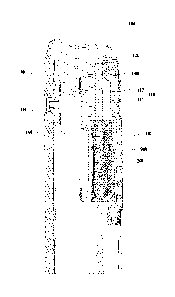
[0012] FIG. 1 is a schematic diagram of a partial structure of a first
mobile terminal
according to an embodiment of this disclosure;
[0013] FIG. 2 is a schematic diagram of a partial structure of a second
mobile terminal
according to an embodiment of this disclosure;
[0014] FIG. 3 is a schematic diagram of a partial structure of a third
mobile terminal
according to an embodiment of this disclosure; and
[0015] FIG. 4 is a schematic diagram of a partial structure of a fourth
mobile terminal
according to an embodiment of this disclosure.
[0016] Description of reference signs:
[0017] 100-housing, 110-inner cavity, 111-receiver front cavity, 112-
receiver rear cavity,
120-middle frame, 130-first screen cover, 131-first receiver decoration cover,
140-battery cover,
141-second sound hole, 150-second screen cover, 151-second receiver decoration
cover, 152-
second sound hole, 160-main board upper cover, 200-receiver, 300-dust screen,
400-elastic pad,
500-seal ring, and 500'-seal ring.
3
Date Recue/Date Received 2021-01-07
DESCRIPTION OF EMBODIMENTS
[0018] To make the purpose, technical solutions, and advantages of this
disclosure clearer,
the following clearly and completely describes the technical solutions of this
disclosure with
reference to specific embodiments and the accompanying drawings in this
disclosure.
Apparently, the described embodiments are merely some rather than all of the
embodiments of
this disclosure. All other embodiments obtained by a person of ordinary skill
in the art based
on the embodiments of this disclosure without creative efforts shall fall
within the protection
scope of this disclosure.
[0019] The technical solutions disclosed in this embodiment of this
disclosure are described
in detail below with reference to the accompanying drawings.
[0020] Referring to FIG. 1 to FIG. 4, an embodiment of this disclosure
discloses a mobile
terminal, and the mobile terminal disclosed includes a housing 100 and a
receiver 200.
[0021] The housing 100 is a peripheral housing of the mobile terminal. The
housing 100
has an inner cavity 110, and the inner cavity 110 is configured to provide an
installation space
for other components of the mobile terminal. The receiver 200 is provided in
the inner cavity
110 of the housing 100. Usually, the receiver 200 is secured in the inner
cavity 110 of the
housing 100 by using a connection structure or a connection element.
[0022] The inner cavity 110 includes a receiver front cavity 111 and a
receiver rear cavity
112, where the receiver front cavity 111 and the receiver rear cavity 112 are
isolated from each
other. The receiver front cavity 111 and the receiver rear cavity 112 are
respectively located on
front and rear sides of the receiver 200 in a vibration direction of a
diaphragm of the receiver
200. The receiver front cavity 111 and the receiver rear cavity 112 are sealed
and isolated by
using other components installed in the inner cavity 110.
[0023] It should be noted that the receiver front cavity 111 is a cavity
facing towards a front
side of the receiver 200 (a side surface on which the diaphragm is disposed),
and the receiver
rear cavity 112 is a cavity facing towards a back side of the receiver 200.
Certainly, vibration
4
Date Recue/Date Received 2021-01-07
of the diaphragm of the receiver causes vibration of air in the receiver front
cavity 111 and the
receiver rear cavity 112.
[0024] The housing 100 is provided with a first sound hole, and the first
sound hole
communicates with the receiver front cavity 111 and an external environment.
The housing 100
is further provided with a second sound hole, and the second sound hole
communicates with
the receiver rear cavity 112 and the external environment.
[0025] At present, mobile terminals are becoming increasingly light and
thin, and the
receiver rear cavity 112 has an increasingly small volume, leading to a
smaller equivalent sound
capacity of the receiver rear cavity 112 and further resulting in a poor low-
frequency effect of
the receiver 200. In the mobile terminal disclosed in this embodiment of this
disclosure, the
housing 100 is provided with the second sound hole, and the second sound hole
can
communicate with the receiver rear cavity 112 and the external environment, so
as to increase
air flow in the receiver rear cavity 112, thereby improving an equivalent
sound capacity of the
receiver rear cavity 112 and achieving a purpose of optimizing the low-
frequency effect.
[0026] Instead of using a method in which the equivalent sound capacity is
improved by
increasing the volume of the receiver back cavity 112, the mobile terminal
disclosed in this
embodiment of this disclosure improves the equivalent sound capacity by
increasing the air
flow in the receiver rear cavity 112, thereby ensuring that a relatively small
volume remains for
the receiver rear cavity 112. This is good for designing lighter and thinner
mobile terminals
under the premise that the low-frequency effect is not affected.
[0027] Certainly, during the actual working process, sound generated by the
receiver 200 is
transmitted through the first sound hole, and may also be transmitted through
the second sound
hole. Obviously, as a result, both sides of the mobile terminal have sound
outlets, thereby
undoubtedly facilitating use by the user.
[0028] In order to improve a flow effect of air driven in the receiver rear
cavity 112, in an
optional solution, the second sound hole may be provided at a part of the
housing 100 opposite
to the back side of the receiver 200. In this case, vibration of the diaphragm
of the receiver 200
Date Recue/Date Received 2021-01-07
helps the air in the receiver rear cavity 112 flow out of the second sound
hole. Specifically, a
quantity of the second sound holes may be at least two, and the at least two
second sound holes
are evenly distributed, further optimizing the air flow effect.
[0029] During the actual working process, the first sound hole and the
second sound hole
need to communicate with the receiver front cavity 111 and the receiver rear
cavity 112,
respectively, and the receiver front cavity 111 and the receiver rear cavity
112 are located in the
mobile terminal. In order to avoid affecting other components inside the inner
cavity 110, the
first sound hole and the second sound hole each are provided with a dust-proof
component.
Specifically, the dust-proof component may be a dust screen or a waterproof
breathable film.
[0030] As mentioned above, the receiver front cavity 111 and the receiver
rear cavity 112
are formed in a plurality of manners. In this embodiment of this disclosure,
the housing 100
may include a middle frame 120 and a first screen cover 130 that is disposed
at the top of the
middle frame 120. A main board upper cover 160 is installed in the inner
cavity 110, and the
main board upper cover 160 is used for installation of a main board of the
mobile terminal, and
certainly may be also used for installation of other components for the mobile
terminal. The
receiver 200 is installed on the main board upper cover 160. The receiver 200,
the main board
upper cover 160, the middle frame 120, and the first screen cover 130 form an
enclosed receiver
front cavity 111, and the first screen cover 130 is provided with the first
sound hole. The
foregoing structure can make full use of the existing components of the mobile
terminal to form
the receiver front cavity 111.
[0031] The first screen cover 130 is usually a glass cover. In order to
improve a decorative
effect, the first screen cover 130 may include a first receiver decoration
cover 131, and the first
receiver decoration cover 131 is provided with the first sound hole. The first
sound hole is
provided in the first receiver decoration cover 131, better ensuring
appearance performance of
the mobile terminal.
[0032] On the basis of the housing 100 with the above structure, the
housing 100 may
further include a battery cover 140, where the battery cover 140, the middle
frame 120, the main
6
Date Recue/Date Received 2021-01-07
board upper cover 160, and the receiver 200 form an enclosed receiver rear
cavity 112, and the
battery cover 140 is provided with a second sound hole 141.
[0033] Certainly, for the mobile terminals with different structures, the
receiver rear cavity
112 is formed by different components. The housing 100 may further include a
second screen
cover 150. The second screen cover 150, the middle frame 120, the main board
upper cover
160, and the receiver 200 form the enclosed receiver rear cavity 112, and the
second screen
cover 150 is provided with a second sound hole 152. In this case, the mobile
terminal is usually
a dual-screen mobile terminal, and disposition of the foregoing second sound
hole 152 can be
better adapted to double-side operation of calling for a device.
[0034] Similarly, the second screen cover 150 may include a second receiver
decoration
cover 151, and the second receiver decoration cover 151 is provided with the
second sound hole
152.
[0035] For a purpose of waterproofing, a dust screen 300 may be provided
between the
battery cover 140 or the second screen cover 150 and the receiver 200, and the
dust screen 300
may cover the second sound hole 141 or the second sound hole 152.
[0036] The receiver 200 is a component in the related art, the front side
of the receiver has
better waterproof performance, and the rear side has poorer waterproof
performance. Therefore,
a better waterproof element needs to be provided for the rear side of the
receiver 200. On this
basis, in an optional solution, the waterproof breathable film may be disposed
between the
battery cover 140 or the second screen cover 150 and the receiver 200. The
waterproof
breathable film, is not water permeable but air permeable, so as to ensure
that the air flow during
the sound generation process is not affected. The dust screen 300 and the
waterproof breathable
film can be directly bonded to the battery cover 140 or the second screen
cover 150 by using
glue.
[0037] The mobile terminal disclosed in the embodiments of this disclosure
may further
include an elastic pad 400, where the elastic pad 400 is disposed on an edge
of the rear side of
the receiver 200 and is fixedly connected to the dust screen 300 or the
waterproof and breathable
7
Date Recue/Date Received 2021-01-07
film. The dust screen 300 or the waterproof breathable film and the elastic
pad 400 are secured
between the battery cover 140 or the second screen cover 150 and the receiver
200. The elastic
pad 400 has good elasticity, and the elastic pad 400 is compressed after the
mobile terminal is
assembled, so as to indirectly implement more stable installation of the dust
screen 300.
[0038] During specific implementation, the elastic pad 400 and the dust
screen 300 or the
waterproof breathable film may be glued to form a whole, and the formed whole
is sandwiched
between the battery cover 140 or the second screen cover 150 and the receiver
200. Certainly,
one side of the whole formed by the elastic pad 400 and the dust screen 300 or
the waterproof
breathable film may be fixedly glued to the receiver 200 in advance, and the
other side is pressed
against the battery cover 140 or the second screen cover 150. Alternatively,
one side of the
whole formed by the elastic pad 400 and the dust screen 300 or the waterproof
breathable film
may be fixedly glued to the battery cover 140 or the second screen cover 150,
and the other side
is pressed against the receiver 200.
[0039] As shown in FIG. 4, the mobile terminal disclosed in this embodiment
of this
disclosure may further include a sealing ring 500 (or a sealing ring 500').
The sealing ring 500
is disposed in the receiver rear cavity 112 and encircles the receiver 200.
Encircling the receiver
200 with the sealing ring 500 reduces space in the receiver rear cavity 112,
so that the air is all
discharged from the receiver rear cavity 112 during vibration of the
diaphragm. This solution
can also reduce a difference between sound transmitted through the first sound
hole and sound
transmitted through the second sound hole, to obtain the same hearing sense on
both sides of
the mobile terminal. Certainly, disposition of the sealing ring 500 can
further implement
functions of sealing and protecting the receiver 200, preventing the receiver
200 from being
affected by water and dust that enter the receiver rear cavity 112 from a
joint between the middle
frame 120 and the battery cover 140.
[0040] In a specific implementation, both the elastic pad 400 and the
sealing ring 500 may
be foam elements, the elastic pad 400 does not need to be used for sealing,
and the sealing ring
500 provides the sealing function. The elastic pad 400 is mainly used for
installing the dust
8
Date Recue/Date Received 2021-01-07
screen 300 or the waterproof breathable film, and disposition of the elastic
pad 400 does not
block space between the dust screen 300 or the waterproof breathable film and
the elastic pad
400 from communicating with the second sound hole.
[0041] The mobile terminal disclosed in this embodiment of this disclosure
may be a mobile
phone, a tablet computer, a wearable device, or the like, and a specific type
of the mobile
terminal is not limited in this embodiment of this disclosure.
[0042] The foregoing embodiments of this disclosure focus on differences
between various
embodiments. The embodiments can be combined to form a preferred embodiment
provided
that the different optimization features between the embodiments are not
contradictory. For
brevity of the specification, details are not described herein.
[0043] The foregoing descriptions are only embodiments of this disclosure,
but are not
intended to limit this disclosure. For a person skilled in the art, this
disclosure may be subject
to various variations and changes. Any modifications, equivalent replacements,
and
improvements made without departing from the spirit and principle of this
disclosure shall fall
within the protection scope of the claims of this disclosure.
9
Date Recue/Date Received 2021-01-07