Note: Descriptions are shown in the official language in which they were submitted.
CA 03105469 2020-12-31
1
DESCRIPTION
CYLINDRICAL MEMBER FOR IMPLANTATION
Technical Field
[0001]
The present invention relates to a cylindrical body for an implant.
Background Art
[0002]
Biodegradable polymers are widely used in medical applications, such as, for
example, medical coating materials, vascular embolization materials, suture
threads
and DDS carriers. Medical coating materials to be implanted in the body are
retained in the body, and therefore, they need to be nontoxic, and to be
eventually
degraded and discharged outside the body.
[0003]
In particular, coating materials which come into contact with blood are
required to be biocompatible, since their original functions may be lost if
they were
to induce thrombus formation.
[0004]
A block copolymer of a polyalkylene glycol and an aliphatic polyester has
been reported as a biodegradable polymer having an excellent degradability and
antithrombogenicity as described above (Patent Literatures 1 and 2).
[0005]
Further, an artificial blood vessel has also been reported, in which a
copolymer obtained by mixing a component(s) selected from L-lactic acid, D,L-
lactic acid, glycolic acid and e-caprolactone, with a component(s) selected
from
Date recue/Date Received 2020-12-31
CA 03105469 2020-12-31
2
polyvinyl alcohol and polyethylene glycol, is used as a biodegradable
synthetic
polymer, and in which such a biodegradable synthetic polymer is coated on a
cylindrical article composed of fibers (Patent Literature 3).
Citation List
Patent Literature
[0006]
Patent Literature 1: JP 9-309947 A
Patent Literature 2: WO 1996/021056 A
Patent Literature 3: JP 2004-313310 A
Summary of Invention
Technical Problem
[0007]
However, since the block copolymer disclosed in Patent Literature 1 has a
high polyalkylene glycol content, the copolymer swells when it comes into
contact
with blood, leading to the elongation of the resulting artificial blood
vessel. The
elongation of the artificial blood vessel may lead to a decrease in the inner
diameter
of the blood vessel, resulting in an increase in the shear rate of blood.
Further, in
the case of a substrate composed of fibers, a decrease in fiber density causes
an
increase in the volume of voids into which blood components infiltrate. In any
of
the cases, the adhesion and aggregation of blood platelets are accelerated,
leading to
thrombus formation.
[0008]
The block copolymer disclosed in Patent Literature 2 has a low polyalkylene
glycol content, and thus the elongation due to swelling does not occur;
however, the
block copolymer has a high Young's modulus. Due to having a high Young's
Date recue/Date Received 2020-12-31
CA 03105469 2020-12-31
3
modulus, the kink resistance of the resulting artificial blood vessel after
being coated
with the block copolymer is reduced. As a result, the artificial blood vessel
fails to
conform to the movement of a living body and buckles, leading to the occlusion
of
the artificial blood vessel.
[0009]
Thus, even if a conventional block copolymer is used in an artificial blood
vessel, there is a possibility that a high patency rate required cannot be
maintained,
because of its high swelling property and high Young's modulus.
[0010]
Further, in the artificial blood vessel disclosed in Patent Literature 3,
since
polyethylene glycol is mixed in the biodegradable polymer to be coated on the
artificial blood vessel, the polyethylene glycol is dissolved at an early
stage of
implantation, resulting in a failure to maintain the antithrombogenicity.
Accordingly, a further improvement is needed, in order to use the artificial
blood
vessel as an implant capable of maintaining a high patency rate.
[0011]
Therefore, an object of the present invention is to provide a cylindrical body
for an implant capable of maintaining a high patency rate, by achieving a good
antithrombogenicity, a low swelling property and a low Young's modulus.
Solution to Problem
[0012]
The present inventors have found out, as a result of intensive studies to
solve
the above mentioned problems, the following inventions (1) to (9).
(1) A cylindrical body for an implant, including:
a cylindrical substrate having an elongation rate in the longitudinal
direction,
as measured under a tensile load of 20 N, of from 5 to 100%; and
Date recue/Date Received 2020-12-31
CA 03105469 2020-12-31
4
a block copolymer composed of a polyalkylene glycol block(s) and a
polyhydroxyalkanoic acid block(s);
wherein the ratio of the total mass of the alkylene glycol residue(s) with
respect to the total mass of the block copolymer is from 5 to 25%; and wherein
the
block copolymer has a Young's modulus, as measured in the form of a film, of
200
MPa or less.
(2) The cylindrical body according to (1), wherein the
polyhydroxyalkanoic acid
block includes a residue selected from the group consisting of lactic acid,
glycolic
acid and caprolactone residues.
(3) The cylindrical body according to claim 2,
wherein the polyhydroxyalkanoic acid block includes a caprolactone
residue(s); and
wherein the ratio of the total mass of the caprolactone residue(s) with
respect
to the total mass of the block copolymer is from 15 to 80%.
(4) The cylindrical body according to (2) or (3),
wherein the polyhydroxyalkanoic acid block includes a glycolic acid
residue(s); and
wherein the ratio of the total mass of the glycolic acid residue(s) with
respect
to the total mass of the block copolymer is from 10% or less.
(5) The cylindrical body according to any one of (1) to (4), wherein the
cylindrical substrate satisfies the following Formula 1:
(L2 -L1)/L1> 0.1 Formula 1
wherein Li represents a gauge length when the cylindrical substrate is
compressed in the longitudinal direction thereof at a stress of 0.01 cN/dtex,
wherein
the gauge length is the distance between gauge lines drawn on the outer
periphery of
the cylindrical substrate, spaced apart by a distance 5 times the maximum
value of
the outer diameter of the cylindrical substrate as measured without applying a
stress
Date recue/Date Received 2020-12-31
CA 03105469 2020-12-31
to the cylindrical substrate; and
wherein L2 represents the gauge length when the cylindrical substrate is
elongated in the longitudinal direction thereof at a stress of 0.01 cN/dtex.
(6) The cylindrical body according to any one of (1) to (5), wherein the
5 cylindrical substrate satisfies the following Formula 2:
0.03 < (a - b) / a < 0.2 Formula 2
wherein a represents the outer diameter of the cylindrical substrate as
measured when the cylindrical substrate is compressed in the longitudinal
direction
thereof at a stress of 0.01 cN/dtex; and
wherein b represents the outer diameter of the cylindrical substrate as
measured when the cylindrical substrate is elongated in the longitudinal
direction
thereof at a stress of 0.01 cN/dtex.
(7) The cylindrical body according to any one of (1) to (6), wherein the
surface
roughness of the inner surface of the cylindrical substrate is 100 pm or less.
(8) An artificial blood vessel including the cylindrical body according to
any one
of (1) to (7).
(9) A stent graft including the cylindrical body according to any one
of (1) to (7).
Advantageous Effects of Invention
[0013]
The cylindrical body for an implant according to the present invention is
capable of maintaining a high patency rate hitherto unachievable, by forming
the
cylindrical body by coating a block copolymer which is composed of a
polyalkylene
glycol block(s) and a polyhydroxyalkanoic acid block(s) and whose monomer
weight
ratio is controlled, on a cylindrical substrate having a specific elongation
rate. In
particular, the cylindrical body for an implant can be suitably used as a
material for a
medical device used for cardiovascular implantation.
Brief Description of Drawings
Date recue/Date Received 2020-12-31
CA 03105469 2020-12-31
6
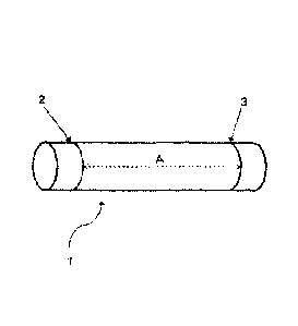
[0014]
FIG. 1 is an explanatory diagram for drawing gauge lines on a cylindrical
substrate.
FIG. 2 is a schematic diagram of an apparatus for measuring the gauge length
upon compression of the cylindrical substrate.
FIG. 3 is a schematic diagram of an apparatus for measuring the gauge length
upon elongation of the cylindrical substrate.
FIG. 4 is an explanatory diagram for measuring the surface roughness of the
inner surface of the cylindrical substrate.
Description of Embodiments
[0015]
The cylindrical body for an implant according to the present invention is
characterized by including:
a cylindrical substrate having an elongation rate in the longitudinal
direction,
as measured under a tensile load of 20 N, of from 5 to 100%; and a block
copolymer
composed of a polyalkylene glycol block(s) and a polyhydroxyalkanoic acid
block(s);
wherein the ratio of the mass of the polyalkylene glycol with respect to the
total mass of the block copolymer is from 5 to 25%; and
wherein a film composed of the block copolymer has a Young's modulus of
200 MPa or less.
[0016]
When the cylindrical substrate has an elongation rate in the longitudinal
direction, as measured under a tensile load of 20 N, of 5% or more, the
cylindrical
substrate more easily conforms to the movement of a living body, when
implanted in
the body. When the cylindrical substrate has an elongation rate of 100% or
less, the
substrate can be prevented from meandering during surgery, and can be more
easily
Date recue/Date Received 2020-12-31
CA 03105469 2020-12-31
7
implanted at an intended site. Based on the above, the cylindrical substrate
preferably has an elongation rate in the longitudinal direction, as measured
under a
tensile load of 20 N, of from 5% to 100%, more preferably from 7% to 75%, and
still
more preferably from 10% to 50%. The elongation rate in the longitudinal
direction, as measured under a tensile load of 20 N, can be measured in
accordance
with Measurement Example 4 to be described later.
[0017]
In the above described cylindrical substrate, when the relationship between
the following gauge lengths Li and L2 is adjusted within the range represented
by
the following Formula 1, it is possible to provide a cylindrical body for an
implant
having an excellent elasticity, flexibility and kink resistance (ability to be
easily
bent).
(L2 -L1)/L1> 0.1 Formula 1
In Formula 1, Li represents a gauge length when the cylindrical substrate is
compressed in the longitudinal direction thereof at a stress of 0.01 cN/dtex,
wherein
the gauge length is the distance between gauge lines drawn on the outer
periphery of
the cylindrical substrate, spaced apart by a distance 5 times the maximum
value of
the outer diameter of a woven fabric as measured without applying a stress to
the
cylindrical substrate; and
L2 represents the gauge length when the cylindrical substrate is elongated in
the longitudinal direction thereof at a stress of 0.01 cN/dtex.
[0018]
When a cylindrical substrate is bent, a stress is applied to the inner
peripheral
side of the bent cylindrical substrate in the direction of compression, and at
the same
time, a stress is applied to the outer peripheral side thereof in the
direction of
elongation. In the above described cylindrical substrate, however, the outer
periphery of the substrate can be sufficiently elongated with respect to the
inner
Date recue/Date Received 2020-12-31
CA 03105469 2020-12-31
8
periphery thereof, due to adjusting the relationship between the following
gauge
lengths Li and L2 within the above described range, and thus, the substrate
has an
excellent kink resistance.
[0019]
Performing an elongation or compression operation at a stress of 0.01 cN/dtex
generally corresponds to applying a stress equivalent to the case in which a
person
elongates or compresses the cylindrical substrate in the longitudinal
direction lightly
by hand. This means, when the relationship between Li and L2 is adjusted
within
the above described range, that the cylindrical substrate has a favorable
maneuverability as well as an excellent elasticity and flexibility, even in
cases where
a person performs a bending operation by hand.
[0020]
The values of the gauge lengths Li and L2 of the cylindrical substrate can be
measured in accordance with Measurement Example 6 to be described later. The
value of the (L2 - Li)! Li described above is preferably 0.15 or more, and
more
preferably 0.18 or more, since the elasticity and flexibility can be improved
even
more. Further, the value of the (L2 - L1) / Li is preferably 1.0 or less.
[0021]
The values of the outer diameter "a" upon compression and the outer
diameter "b" upon elongation, of the cylindrical substrate, and the value of
(a - b)! a,
can be determined from the following a and b measured in accordance with
Measurement Example 7 to be described later. Here, a represents the outer
diameter of the cylindrical substrate as measured when the cylindrical
substrate is
compressed in the longitudinal direction thereof at a stress of 0.01 cN/dtex;
and b
represents the outer diameter of the cylindrical substrate as measured when
the
cylindrical substrate is elongated in the longitudinal direction thereof at a
stress of
0.01 cN/dtex. When the value of (a - b)! a is adjusted within the range
represented
Date recue/Date Received 2020-12-31
CA 03105469 2020-12-31
9
the following Formula 2, the difference in the inner diameter of the
cylindrical
substrate when the elongation and compression occur simultaneously, such as,
for
example, upon bending, is reduced, enabling to ensure a flow channel without
variation. This prevents the occurrence of the turbulence of blood flow and
the like,
thereby inhibiting the thrombus formation.
0.03 < (a - b) / a < 0.2 Formula 2
In Formula 2, a represents the outer diameter of the cylindrical substrate as
measured when the cylindrical substrate is compressed in the longitudinal
direction
thereof at a stress of 0.01 cN/dtex; and
b represents the outer diameter of the cylindrical substrate as measured when
the cylindrical substrate is elongated in the longitudinal direction thereof
at a stress
of 0.01 cN/dtex.
[0022]
The value of (a - b) / a is preferably 0.03 or more and less than 0.2, and
more
preferably 0.05 or more and less than 0.15, because the difference in the
inner
diameter of the cylindrical substrate when the elongation and compression
occur
simultaneously, such as, for example, upon bending, is reduced, enabling to
ensure a
flow channel without variation.
[0023]
In the present specification, the surface roughness of the inner surface of
the
cylindrical substrate is defined as the difference between Ds and Di, when the
distance between an arbitrary point on the outer surface of the cylindrical
substrate
and the intersection of a straight line extending from the arbitrary point on
the outer
surface toward the center of the cylindrical substrate with the inner surface,
is
defined as D; the shortest distance D in the cylindrical substrate is defined
as Ds; and
the longest distance D is defined as Di. Further, the center of the
cylindrical
substrate refers to the point at which variation in the shortest distance from
the center
Date recue/Date Received 2020-12-31
CA 03105469 2020-12-31
of the cylindrical substrate to the inner surface is minimized. The surface
roughness of the inner surface of the cylindrical substrate is preferably 100
pm or
less, more preferably 80 pm or less, and still more preferably 60 pm or less.
The
lower limit of the surface roughness of the inner surface is preferably 3 pm
or more,
5 from the viewpoint of facilitating endothelium formation when the
cylindrical
substrate is used as an artificial blood vessel. When the surface roughness of
the
inner surface of the cylindrical substrate is adjusted within the above
described
range, the turbulence of fluid does not occur, even if the cylindrical
substrate has a
small inner diameter. Particularly, even in the case of using the cylindrical
10 substrate as a narrow artificial blood vessel, there is an advantage
that the turbulence
of blood flow does not occur, and thrombi are less likely to be formed. The
surface
roughness of the inner surface of the cylindrical substrate can be measured in
accordance with Measurement Example 8 to be described later.
[0024]
The water permeability of the cylindrical substrate refers to the property in
which, when a certain pressure is applied to the inner surface of the
cylindrical
substrate, water flows out through the outer surface. In the present
specification,
the value obtained by dividing the amount of water (mL) flowing out through
the
outer surface when a pressure of 16 kPa is applied to the inner surface, by
the unit
area (cm2) and the unit time (min.), is used as an index for evaluating the
water
permeability of the cylindrical substrate. The water permeability is measured
in
accordance with ISO 7198, by dividing the amount of water (mL) flowing out to
the
outer side of the cylindrical substrate when a pressure of 16 kPa is applied
to the
inner surface, by the unit area (cm2) and the unit time (min). When the water
permeability of the cylindrical substrate is 5 mL/cm2/min. or more, the
infiltration of
cells and tissue is facilitated, after the degradation of the block copolymer;
whereas
when the water permeability is 500 mL/cm2/min. or less, the leakage of blood
can be
Date recue/Date Received 2020-12-31
CA 03105469 2020-12-31
11
more easily prevented. Therefore, the water permeability under the conditions
where a pressure of 16 kPa is applied to the inner surface is preferably from
5
mL/cm2/min. to 500 mL/cm2/min., more preferably from 50 mL/cm2/min. to 350
mL/cm2/min., and still more preferably from 100 mL/cm2/min. to 250 mL/cm2/min.
[0025]
Further, the cylindrical substrate preferably has a structure other than a
bellows structure. When the cylindrical substrate has a structure other than a
bellows structure, the inner surface of the cylindrical substrate has no
surface
roughness, and a turbulent flow does not occur even when a fluid flows through
a
narrow space. Particularly, in the case of using the cylindrical substrate as
a narrow
artificial blood vessel, there is an advantage that the turbulence of blood
flow does
not occur, and thrombi are less likely to be formed. Specifically, the
structure other
than a bellows structure refers to a structure of a woven fabric which is
formed by
inserting a stem having a helical or annular corrugated groove(s) into a
cylindrical
article made of fibers, and which has not been heat-set into a waveform or
subjected
to pleating.
[0026]
The above described cylindrical substrate is a hollow substrate composed of
any of the following materials, and examples of the material of the
cylindrical
substrate include synthetic polymers and natural polymers.
[0027]
Examples of the synthetic polymer include polyethylene, polypropylene,
polyvinyl chloride, polystyrene, polyvinyl acetate, polyvinylpyrrolidone,
polyvinyl
alcohol, polyurethane, PTFE, ePTFE, acrylic resins, polyamides, polyacetals,
polycarbonates, polyesters and polysiloxanes; and mixtures and copolymers
thereof.
Examples of the natural polymer include polysaccharides, proteins and natural
rubber, and examples of the proteins include gelatin and collagen.
Date recue/Date Received 2020-12-31
CA 03105469 2020-12-31
12
[0028]
The material of the cylindrical substrate as described above can be in any
shape, and the shape of the material may be, for example, a film, a porous
sheet,
fibers or the like.
[0029]
In cases where the cylindrical substrate is composed of fibers, any of various
types of organic fibers can be used. However, polyesters are preferred from
the
viewpoint of water absorbency and resistance to deterioration. Examples of the
polyester include polyethylene terephthalate and polybutylene terephthalate.
Further, a copolymerized polyester obtained by copolymerizing an aliphatic
dicarboxylic acid, such as isophthalic acid, 5-sodium sulfoisophthalic acid or
adipic
acid, as an acid component, with polyethylene terephthalate or polybutylene
terephthalate, may also be used.
[0030]
The term "biodegradable polymer" as described above refers to a polymer
which has a property to be degraded in a living body. The term which can be
used
interchangeably with the "biodegradable" may be, for example, "bioabsorbable"
or
"biocompatible".
[0031]
The above described block copolymer is characterized by being composed of
a polyalkylene glycol block(s) and a polyhydroxyalkanoic acid block(s).
[0032]
The polyalkylene glycol is a polymer in which one or more alkylene glycols
are polymerized. Examples of the alkylene glycol include a polymer containing
one
or more of ethylene glycol, propylene glycol, oxyethylene glycol dimethyl
ether,
oxypropylene glycol monobutyl ether or oxypropylene glycol diacetate.
[0033]
Date recue/Date Received 2020-12-31
CA 03105469 2020-12-31
13
The polyhydroxyalkanoic acid is one in which one or more hydroxyalkanoic
acids are polymerized. Examples of the hydroxyalkanoic acid include 2-
hydroxypropionic acid (lactic acid), 2-hydroxybutanoic acid, 2-
hydroxypentanoic
acid, 2-hydroxyhexanoic acid, 3-hydroxybutanoic acid (3-hydroxybutyric acid),
3-
hydroxypentanoic acid (3-hydroxyvaleric acid), 3-hydroxyhexanoic acid, 3-
hydroxyheptanoic acid, 3-hydroxyoctanoic acid, 3-hydroxynonanoic acid, 3-
hydroxydecanoic acid, 4-hydroxypentanoic acid, 4-hydroxyhexanoic acid, 4-
hydroxyheptanoic acid, 4-hydroxyoctanoic acid, 5-hydroxyhexanoic acid, 5-
hydroxyheptanoic acid, 6-hydroxyheptanoic acid, 6-hydroxyoctanoic acid, 8-
hydroxynonanoic acid, 8-hydroxydecanoic acid, 9-hydroxydecanoic acid, 9-
hydroxyundecanoic acid, 10-hydroxyundecanoic acid, 10-hydroxydodecanoic acid,
11-hydroxydodecanoic acid and 12-hydroxytridecanoic acid.
[0034]
The ratio of the total mass of the alkylene glycol residue(s) with respect to
the
total mass of the block copolymer refers to the ratio of the total mass of the
alkylene
glycol residue(s) with respect to the mass of all the residues contained in
the block
copolymer, and is calculated from the numerical value obtained by 1H-NMR
measurement, as described in Measurement Example 1 to be described later. When
the ratio of the total mass of the alkylene glycol residue(s) with respect to
the total
mass of the block copolymer is 5% or more, a suitable antithrombogenicity can
be
obtained; whereas when the ratio is 25% or less, a suitable swelling property
can be
obtained. Accordingly, in order to obtain both suitable antithrombogenicity
and
swelling property in a balanced manner, the ratio of the total mass of the
alkylene
glycol residue(s) with respect to the total mass of the block copolymer is
preferably
from 5 to 25%, more preferably from 8 to 22%, and still more preferably from
10 to
20%.
[0035]
Date recue/Date Received 2020-12-31
CA 03105469 2020-12-31
14
The ratio of the total mass of the caprolactone residue(s) with respect to the
total mass of the block copolymer refers to the ratio of the total mass of the
caprolactone residue(s) with respect to the mass of all the residues contained
in the
block copolymer, and is calculated from the numerical value obtained by 1E-NMR
measurement, as described in Measurement Example 1 to be described later. When
the ratio of the total mass of the caprolactone residue(s) with respect to the
total mass
of the block copolymer is 15% or more, a suitable Young's modulus value can be
obtained; whereas when the ratio is 80% or less, a suitable degradability can
be
obtained. Accordingly, in order to obtain both suitable degradability and
Young's
modulus in a balanced manner, the ratio of the total mass of the caprolactone
residue(s) with respect to the total mass of the block copolymer is preferably
from 15
to 80%, more preferably from 20 to 70%, and still more preferably from 25 to
60%.
[0036]
The ratio of the total mass of the glycolic acid residue(s) with respect to
the
total mass of the block copolymer refers to the ratio of the total mass of the
glycolic
acid residue(s) with respect to the mass of all the residues contained in the
block
copolymer, and is calculated from the numerical value obtained by 1H-NMR
measurement, as described in Measurement Example 1 to be described later. The
ratio of the total mass of the glycolic acid residue(s) with respect to the
total mass of
the block copolymer is preferably 10% or less, because a suitable Young's
modulus
value can be obtained, and the ratio is more preferably 7% or less, and still
more
preferably 5% or less.
[0037]
The polyalkylene glycol block may be a single polyalkylene glycol molecule,
or may be a plurality of polyalkylene glycol molecules connected via a
linker(s).
The polyalkylene glycol molecule(s) constituting the polyalkylene glycol block
preferably have a weight average molecular weight of from 7,000 to 170,000,
more
Date recue/Date Received 2020-12-31
CA 03105469 2020-12-31
preferably from 8,000 to 100,000, and still more preferably from 10,000 to
50,000.
[0038]
The Young's modulus of a film composed of the block copolymer can be
evaluated in accordance with the method described in Measurement Example 2 to
be
5 described later. In order for the cylindrical body for an implant which
has been
coated with the block copolymer to exhibit a favorable kink resistance, the
film
composed of the block copolymer preferably has a Young's modulus of 200 MPa or
less, more preferably 100 MPa or less, and still more preferably 10 MPa or
less.
[0039]
10 The block copolymer needs to be formed into a film, in order to coat
the
cylindrical substrate. Therefore, the block copolymer preferably has a weight
average molecular weight of 10,000 or more. Although the upper limit is not
particularly limited, the weight average molecular weight of the block
copolymer is
preferably 1,600,000 or less, more preferably 800,000 or less, and still more
15 preferably 400,000 or less, in order to improve formability. The weight
average
molecular weight can be determined by gel permeation chromatography (GPC), for
example, by the method shown below.
[0040]
The block copolymer is dissolved in chloroform, and passed through a 0.45
pm syringe filter (DISMIC-13HP; manufactured by ADVANTEC Co., Ltd.) to
remove impurities and the like. Thereafter, the measurement is carried out by
GPC,
and the weight average molecular weight of the block copolymer is calculated.
Name of apparatus: Prominence (manufactured by Shimadzu Corporation)
Mobile phase: chloroform (for HPLC) (manufactured by Wako Pure
Chemical Industries, Ltd.)
Flow velocity: 1 mL/min
Column: TSK gel GMHHR-M (diameter: 7.8 mm >< length 300 mm;
Date recue/Date Received 2020-12-31
CA 03105469 2020-12-31
16
manufactured by Tosoh Corporation)
Detector: UV (254 nm), RI
Column, detector temperature: 35 C
Reference material: polystyrene
[0041]
The swelling property as described above refers to the property of a polymer
to absorb water and swell, when dipped in water. In the present specification,
the
swelling ratio is used as an index for evaluating the swelling property.
[0042]
The swelling ratio of a film composed of the block copolymer can be
evaluated by the method described in Measurement Example 3 to be described
later.
When the swelling ratio of the film composed of the block copolymer is -10% or
more, it is possible to prevent the peeling of the film from the cylindrical
substrate,
even if the film composed of the block copolymer has shrunk. When the swelling
ratio is 20% or less, it is possible to prevent thrombus formation due to an
excessive
elongation of the cylindrical body for an implant, even if the film composed
of the
block copolymer has expanded. Accordingly, the swelling ratio of the film
composed of the block copolymer is preferably from -10% to 20%, more
preferably
from -5% to 15%, and still more preferably from 0% to 10%.
[0043]
The polyhydroxyalkanoic acid block and the block copolymer can be
synthesized, for example, by: a method in which a cyclic monomer is subjected
to
ring-opening polymerization in the presence of an initiator and a catalyst
(ring-
opening polymerization method); a method in which a molecule of the same or a
different kind of block copolymer is bound to each of both ends of the block
copolymer, one at a time, through their ends, in the presence of a catalyst or
a
condensing agent (multimerization method); and a method in which the ring-
opening
Date recue/Date Received 2020-12-31
CA 03105469 2020-12-31
17
polymerization method and the multimerization method are combined.
[0044]
Examples of the cyclic monomer include D,L-lactide, L-lactide, glycolide,
D,L-lactide-co-glycolide, L-lactide-co-glycolide, 6-caprolactone, y-
butyrolactone, 6-
valerolactone, 6-caprolactone-co-lactic acid and 6-caprolactone-co-glycolic
acid-co-
lactic acid.
[0045]
Examples of the catalyst which can be used in the production by the ring-
opening polymerization method include polymerization catalysts such as
commonly
used germanium-based catalysts, titanium-based catalysts, antimony-based
catalysts
and tin-based catalysts. Specific examples of such a polymerization catalyst
include tin(II) octylate, trifluoride antimony, zinc powder, dibutyltin(IV)
oxide and
tin(II) oxalate. The method for adding the catalyst to a reaction system is
not
particularly limited. However, preferred is a method in which the catalyst is
added
during the charging of raw materials, in a state where the catalyst is
dispersed in the
raw materials, or alternatively, the catalyst is added at the time of starting
decompression, in a dispersed state. The amount of the catalyst used is
preferably
from 0.01 to 3% by weight, and more preferably from 0.05 to 1.5% by weight, in
terms of metal atoms, with respect to the total amount of the monomers to be
used.
[0046]
Examples of a metal catalyst which can be used in the production by the
multimerization method include metals such as tin, titanium, lead, zinc,
cobalt, iron,
lithium and rare earth metals; and metal alkoxides, metal halogen compounds,
organic carboxylates, carbonates, sulfates and oxides of these metals.
However, a
tin compound is preferred from the viewpoint of polymerization reactivity.
[0047]
Examples of the tin compound which can be used include tin powder, tin(II)
Date recue/Date Received 2020-12-31
CA 03105469 2020-12-31
18
chloride, tin(IV) chloride, tin(II) bromide, tin(IV) bromide, ethoxytin(II), t-
butoxytin(IV), isopropoxytin(IV), tin(II) acetate, tin(IV) acetate, tin(II)
octylate,
tin(II) laurate, tin(II) myristate, tin(II) palmitate, tin(II) stearate,
tin(II) oleate, tin(II)
linoleate, tin(II) acetylacetonate, tin(II) oxalate, tin(II) lactate, tin(II)
tai ti ate, tin(II)
pyrophosphate, tin(II) p-phenolsulfonate, tin(II) bis(methanesulfonate),
tin(II)
sulfate, tin(H) oxide, tin(IV) oxide, tin(H) sulfide, tin(IV) sulfide,
dimethyltin(IV)
oxide, methylphenyltin(IV) oxide, dibutyltin(IV) oxide, dioctyltin(IV) oxide,
diphenyltin(IV) oxide, tributyltin oxide, triethyltin(IV) hydroxide,
triphenyltin(IV)
hydroxide, tributyltin hydride, monobutyltin(IV) oxide, tetramethyltin(IV),
tetraethyltin(IV), tetrabutyltin(IV), dibutyldiphenyltin(IV),
tetraphenyltin(IV),
tributyltin(IV) acetate, triisobutyltin(IV) acetate, triphenyltin(IV) acetate,
dibutyltin
diacetate, dibutyltin dioctoate, dibutyltin(IV) dilaurate, dibutyltin(IV)
maleate,
dibutyltin bis(acetylacetonate), tributyltin(IV) chloride, dibutyltin
dichloride,
monobutyltin trichloride, dioctyltin dichloride, triphenyltin(IV) chloride,
tributyltin
sulfide, tributyltin sulfate, tin(II) methanesulfonate, tin(II)
ethanesulfonate, tin(II)
trifluoromethanesulfonate, ammonium hexachlorostannate(IV), dibutyltin
sulfide,
diphenyltin sulfide, triethyltin sulfate and tin(II) phthalocyanine.
[0048]
Further, examples of a non-metal catalyst or the condensing agent which can
be used in the production by the multimerization method include 4,4-
dimethylaminopyridine, 4,4-dimethylaminopyridinium p-toluenesulfonate, 143-
(dimethylamino)pr0py11-3-ethylcarbodiimide, 1-ethy1-3-(3-
dimethylaminopropyl)carbodiimide hydrochloride, N,N'-dicyclohexylcarbodiimide,
N,N'-diisopropylcarbodiimide, N,N'-carbonyldiimidazole, 1,1'-carbonyldi(1,2,4-
2 5 triazole), 4-(4,6-dimethoxy-1,3,5-triazin-2-y1)-4-
methylmorpholinium=chloride n-
hydrate, (4,6-dimethoxy-1,3,5-triazin-2-y1)-(2-octoxy-2-
oxoethyl)dimethylammonium trifluoromethanesulfonate, 1H-benzotriazol-1 -
Date recue/Date Received 2020-12-31
CA 03105469 2020-12-31
19
yloxytris(dimethylamino)phosphonium hexafluorophosphate, 1H-benzotriazol-1-
yloxytripyrrolidinophosphonium hexafluorophosphate, (7-azabenzotriazol-1-
yloxy)tripyrrolidinophosphonium hexafluorophosphate,
chlorotripyrrolidinophosphonium hexafluorophosphate,
bromotris(dimethylamino)phosphonium hexafluorophosphate, 3-
(diethoxyphosphoryloxy)-1,2,3-benzotri azin-4(3H)-one, 0-(benzotriazol-1-y1)-
N,N,N',N' -tetramethyluronium hexafluorophosphate, 0-(7-azabenzotriazol-1-y1)-
N,N,N',N'-tetramethyluronium hexafluorophosphate, 0-(N-succinimidy1)-
N,N,N',N'-tetramethyluronium tetrafluoroborate, 0-(N-succinimidy1)-N,N,N',N'-
1 0 tetramethyluronium hexafluorophosphate, 0-(3,4-dihydro-4-oxo-1,2,3-
benzotriazine-
3-y1)-N,N,N',N'-tetramethyluronium tetrafluoroborate, S-(1-oxide-2-pyridy1)-
N,N,N',N'-tetramethyluronium tetrafluoroborate, 0-[2-oxo-1(2H)-pyridyll-
N,N,N',N'-tetramethyluronium tetrafluoroborate, { {[(1-cyano-2-ethoxy-2-
oxoethylidene)amino] oxy}-4-morpholinomethyleneldimethylammonium
hexafluorophosphate, 2-chloro-1,3-dimethylimidazolinium hexafluorophosphate, 1-
(chloro-1-pyrrolidinylmethylene)pyrrolidinium hexafluorophosphate, 2-fluoro-
1,3-
dimethylimidazolinium hexafluorophosphate, and fluoro-N,N,N',N'-
tetramethylformamidinium hexafluorophosphate.
[0049]
In the case of performing the multimerization method, a linker molecule
having two or more carboxyl groups, isocyanate groups, amino groups or
hydroxyl
groups may be used, at each end.
[0050]
Examples of the linker molecule having two or more carboxyl groups include
those having two or more carboxyl groups at their branching ends, among
dicarboxylic acids, citric acid and multi-branched polymers; and acid halides,
acid
anhydrides and esters of the above described dicarboxylic acids, citric acid
and
Date recue/Date Received 2020-12-31
CA 03105469 2020-12-31
multi-branched polymers. That is, the above described carboxylic acid groups
may
be converted to acid halide structures, ester structures or acid anhydride
structures.
Examples of the dicarboxylic acid include oxalic acid, malonic acid, succinic
acid,
glutaric acid, adipic acid, pimelic acid, suberic acid, azelaic acid, sebacic
acid, malic
5 acid, tartaric acid and dodecanedioic acid. Examples of the multi-
branched polymer
include hyper-branched polymers and dendrimers
[0051]
Examples of the linker molecule having two or more isocyanate groups
include hexamethylene diisocyanate (HDI), 4,4'-diphenylmethane diisocyanate
10 (MDI), 4,4'-dicyclohexylmethane diisocyanate, cyclohexyl diisocyanate
(CHDI) and
2,4-toluene diisocyanate (TDI). Examples of the linker molecule having two or
more amino groups include ethylenediamine, putrescine, cadaverine,
hexamethylenediamine and phenylenediamine.
[0052]
15 Examples of the linker molecule having two or more hydroxyl groups
include
ethylene glycol, 1,3-propanediol, 1,4-butanediol, 1,5-pentanediol, 1,6-
hexanediol,
1,7-heptanediol, 1,8-octanediol, 1,9-nonanediol, 1,10-decanediol, 1,11-
undecanediol,
1,12-dodecanediol, 1,13-tridecanediol, 1,14-tetradecanediol, 1,15-
pentadecanediol,
1,16-hexadecanediol and oxoaliphatic diols.
20 [0053]
When a linker molecule having a plurality of carboxyl, isocyanate, amino and
hydroxyl groups within the same molecule is used as the above described linker
molecule, a branched-chain copolymer can be synthesized in which the linker
serves
as a branching point. Examples of the linker molecule having a plurality of
carboxyl, isocyanate, amino and hydroxyl groups within the same molecule
include
2,2-bis(hydroxymethyl)propionic acid, malic acid and diamine diols.
[0054]
Date recue/Date Received 2020-12-31
CA 03105469 2020-12-31
21
By allowing a polyalkylene glycol (having hydroxyl groups at both ends) to
react with any of the linker molecules to react in advance, or subjecting the
hydroxyl
groups to functional group conversion, it is possible to obtain a polyalkylene
glycol
having carboxyl groups, isocyanate groups or amino groups at both ends, or a
polyalkylene glycol having carboxyl groups, isocyanate groups, or amino groups
at
one end, and these can be used as raw materials for producing the copolymer.
[0055]
In cases where the polymerization reaction is living, namely, when it is
possible to initiate a polymerization reaction continuously from the ends of
the
polymer, the operation of adding monomers to the block copolymer solution
after the
completion of the polymerization reaction can be repeated, to perform the
multimerization method.
[0056]
In the present specification, the term "residue" is used to refer, in
principle, to
each of the repeating units of the chemical structures derived from the above
described monomers, in the chemical structure of a block copolymer obtained by
polymerizing two or more types of monomers including the monomers.
[0057]
For example, when lactic acid (CH3CH(OH)COOH) is polymerized with
caprolactone (c-caprolactone) represented by the following Chemical Formula
(I), to
form a block copolymer of lactic acid and caprolactone, a lactic acid residue
has the
structure represented by the following Chemical Formula (II), and a
caprolactone
residue has the structure represented by the following Chemical Formula (III).
[Chem. 1]
Date recue/Date Received 2020-12-31
CA 03105469 2020-12-31
22
= = = (I)
[Chem. 2]
0
f'.0 )114
= = = (II)
[Chem. 3].
0
= = = (III)
[0058]
As an exception, however, in cases where a dimer of lactide or the like is
used
as a monomer, the "residue" refers to one of the two repeating structures
derived
from the dimer. For example, when dilactide (L+)-lactide) represented by the
following Chemical Formula (IV) is polymerized with caprolactone, the chemical
structure of the resulting block copolymer includes a structure in which the
structure
represented by the Chemical Formula (II) shown above is repeated twice, as a
dilactide residue. In this case, one of the two repeating structures is taken
as the
lactic acid residue, and it is regarded that two lactic acid residues derived
from
dilactide are formed.
[Chem. 4]
fOaty$01
100A0
= = = (IV)
[0059]
Date recue/Date Received 2020-12-31
CA 03105469 2020-12-31
23
The properties of the block copolymer coated on the cylindrical substrate can
be analyzed as follows. For example, the copolymer coated on the cylindrical
substrate is dipped in a solvent such as chloroform, and the resulting extract
is dried
to obtain a solid. The resulting solid is subjected to measurements such as
those
described in Measurement Examples 1 to 3 to be described later.
[0060]
The kink radius may be used, for example, as an index for evaluating the kink
resistance. The "kink radius" as used herein refers, when a loop is formed
with the
cylindrical body for an implant and the diameter of the loop is gradually
reduced, to
the minimum loop radius of the loop at which buckling does not occur. The kink
radius can be evaluated by the method described in Measurement Example 10 to
be
described later. Too large a kink radius may lead to an inability to conform
to the
movement of surrounding tissue after being implanted in a living body, or an
inability to be implanted to a bent portion. The kink radius is preferably 15
mm or
less, and more preferably 10 mm or less, because it facilitates the
cylindrical body to
conform to the movement of surrounding tissue after being implanted in a
living
body, and facilitates the implantation to a bent portion.
[0061]
The coating thickness of the block copolymer refers to the thickness of the
layer of the block copolymer in a cross section of the cylindrical body for an
implant.
The coating thickness of the block copolymer can be evaluated by the method
described in Measurement Example 11 to be described later. When the coating
thickness of the block copolymer is 1 prn or more, the pressure resistance can
be
improved; whereas when the coating thickness of the block copolymer is 500 p.m
or
less, the block copolymer can be degraded in a suitable period of time.
Accordingly, the coating thickness of the block copolymer is preferably from 1
p.m to
500 p.m, more preferably from 10 p.m to 300 p.m, and still more preferably
from 20
Date recue/Date Received 2020-12-31
CA 03105469 2020-12-31
24
lirn to 200 pm.
[0062]
The cylindrical substrate preferably has an inner diameter of from 1 to 10
mm, and more preferably from 2 to 4 mm, in cases where the use as an
artificial
blood vessel or a stent graft is taken into consideration.
[0063]
The artificial blood vessel is a medical device used for replacing a diseased,
living blood vessel, for example, one affected by arteriosclerosis, or for
forming a
by-pass or shunt. Examples of the material of the artificial blood vessel
include
fabrics, polytetrafluoroethylene, biomaterials and synthetic polymer
materials.
Among these, a fabric is preferred, because anticoagulant capacity can be
easily
imparted thereto.
[0064]
The patency rate may be used, for example, as an index for evaluating an
artificial blood vessel. It has been reported, in a human clinical setting,
that the
patency rate in the case of using an artificial blood vessel as a substitute
blood vessel,
in a bypass surgery for obstructive arteriosclerosis in lower limbs, is 60%,
whereas
the patency rate in the case of using an autologous vein is 80%. In
cardiovascular
implantation, such as a cardiac coronary artery bypass operation, an
autologous vein,
not an artificial blood vessel, is selected, taking into consideration the
postoperative
occlusion and stenosis. This means that the difference in the patency rate of
about
20% in the cardiovascular implantation has a significant meaning in a clinical
setting.
However, the use of an autologous vein also entails a problem that it requires
a
removal surgery which imposes a heavy burden on patients, or that there are
some
patients whose quality of veins is too poor to be used to begin with.
Therefore, an
artificial blood vessel having a patency rate equal to or higher than that of
an
autologous vein, that is, an artificial blood vessel having a patency rate of
80% or
Date recue/Date Received 2020-12-31
CA 03105469 2020-12-31
more, has a great significance in a clinical setting.
[0065]
The term "anticoagulant capacity" refers to the capacity to prevent the
coagulation of blood and to inhibit thrombus formation. The anticoagulant
capacity
5 can be imparted, for example, by a method in which heparin or a heparin
derivative
is applied to the surface of the material.
[0066]
The term "stent graft" refers to a medical device in which a stent and an
artificial blood vessel (graft) are combined, and is used for treating
aneurysm, by
10 being retained in a living blood vessel.
Examples
[0067]
The present invention will now be described in specific detail, with reference
15 to Reference Examples, Examples and Comparative Examples. It is noted,
however, that the present invention is in now way limited to these Examples.
[0068]
(Reference Example 1)
A quantity of 50.0 g of L-lactide (PURASORB (registered trademark) L;
20 manufactured by Purac Biomaterials), and 38.5 mL of e-caprolactone
(manufactured
by Wako Pure Chemical Industries, Ltd.), as monomers, were placed in a
separable
flask. Under an argon atmosphere, 0.29 g of tin(II) octylate (manufactured by
Wako Pure Chemical Industries, Ltd.), as a catalyst, which had been dissolved
in
14.5 mL of toluene (super dehydrated) (manufactured by Wako Pure Chemical
25 Industries, Ltd.), and 90 pi., of ion exchanged water as an initiator
were added to the
flask, and a promoter reaction was carried out at 90 C for one hour.
Thereafter, a
copolymerization reaction was allowed to proceed at 150 C for 6 hours, to
obtain a
Date recue/Date Received 2020-12-31
CA 03105469 2020-12-31
26
crude polyhydroxyalkanoic acid A.
[0069]
The thus obtained crude polyhydroxyalkanoic acid A was dissolved in 100
mL of chloroform, and the resultant was added dropwise to 1,400 mL of methanol
in
a stirred state, to obtain precipitates. The above described operation was
repeated
three times, and the resulting precipitates were dried under reduced pressure
at 70 C,
to obtain a polyhydroxyalkanoic acid A.
[0070]
A quantity of 14.2 g of the thus obtained polyhydroxyalkanoic acid A, 0.41 g
of polyethylene glycol (weight average molecular weight: 10,000; manufactured
by
Sigma-Aldrich Inc.) having hydroxy groups at both ends, and 0.42 g of
polyethylene
glycol (weight average molecular weight: 10,200) having carboxyl groups at
both
ends were mixed. To the mixture, 0.56 g of 4,4-dimethylaminopyridinium p-
toluenesulfonate (synthesized by the method described in Non-patent Document
1),
and 0.20 g of 4,4-dimethylaminopyridine (manufactured by Wako Pure Chemical
Industries, Ltd.), as catalysts, were added. Under an argon atmosphere, the
resulting mixture was dissolved in 28 mL of dichloromethane (dehydrated)
(manufactured by Wako Pure Chemical Industries, Ltd.), and 2.06 g of
dicyclohexylcarbodiimide (manufactured by Sigma-Aldrich Co.,) as a condensing
agent, which had been dissolved in 7 mL of dichloromethane was added thereto,
followed by condensation polymerization at room temperature for two days.
[0071]
To the resulting reaction mixture, 60 mL of chloroform was added, and the
resultant was added dropwise to 1,000 mL of methanol in a stirred state, to
obtain
precipitates. The resulting precipitates were dissolved in 100 mL of
chloroform,
and the resultant was added dropwise to 1,000 mL of methanol in a stirred
state, to
obtain precipitates. The above described operation was repeated twice, to
obtain a
Date recue/Date Received 2020-12-31
CA 03105469 2020-12-31
27
purified block copolymer of Reference Example 1, as precipitates.
[0072]
(Reference Example 2)
A block copolymer of Reference Example 2 was obtained in the same manner
as in Reference Example 1, except that, at the time of the addition of 0.20 g
of 4,4-
dimethylaminopyridine (manufactured by Wako Pure Chemical Industries, Ltd.),
the
added amount of the polyhydroxyalkanoic acid A was changed from 14.2 g to 13.4
g,
the added amount of the polyethylene glycol (weight average molecular weight:
10,000; manufactured by Sigma-Aldrich Inc.) having hydroxy groups at both ends
was changed from 0.41 g to 0.82 g, and the added amount of the polyethylene
glycol
(weight average molecular weight: 10,200) having carboxyl groups at both ends
was
changed from 0.42 g to 0.83 g.
[0073]
(Reference Example 3)
A block copolymer of Reference Example 3 was obtained in the same manner
as in Reference Example 1, except that, at the time of the addition of 0.20 g
of 4,4-
dimethylaminopyridine (manufactured by Wako Pure Chemical Industries, Ltd.),
the
added amount of the polyhydroxyalkanoic acid A was changed from 14.2 g to 11.7
g,
the added amount of the polyethylene glycol (weight average molecular weight:
10,000; manufactured by Sigma-Aldrich Inc.) having hydroxy groups at both ends
was changed from 0.41 g to 1.63 g, and the added amount of the polyethylene
glycol
(weight average molecular weight: 10,200) having carboxyl groups at both ends
was
changed from 0.42 g to 1.67 g.
[0074]
(Reference Example 4)
A block copolymer of Reference Example 4 was obtained in the same manner
as in Reference Example 1, except that, at the time of the addition of 0.20 g
of 4,4-
Date recue/Date Received 2020-12-31
CA 03105469 2020-12-31
28
dimethylaminopyridine (manufactured by Wako Pure Chemical Industries, Ltd.),
the
added amount of the polyhydroxyalkanoic acid A was changed from 14.2 g to 10.9
g,
the added amount of the polyethylene glycol (weight average molecular weight:
10,000; manufactured by Sigma-Aldrich Inc.) having hydroxy groups at both ends
was changed from 0.41 g to 2.04 g, and the added amount of the polyethylene
glycol
(weight average molecular weight: 10,200) having carboxyl groups at both ends
was
changed from 0.42 g to 2.08 g.
[0075]
(Reference Example 5)
A block copolymer of Reference Example 5 was obtained in the same manner
as in Reference Example 1, except that, at the time of the addition of 0.20 g
of 4,4-
dimethylaminopyridine (manufactured by Wako Pure Chemical Industries, Ltd.),
the
added amount of the polyhydroxyalkanoic acid A was changed from 14.2 g to 10.1
g,
the added amount of the polyethylene glycol (weight average molecular weight:
10,000; manufactured by Sigma-Aldrich Inc.) having hydroxy groups at both ends
was changed from 0.41 g to 2.45 g, and the added amount of the polyethylene
glycol
(weight average molecular weight: 10,200) having carboxyl groups at both ends
was
changed from 0.42 g to 2.50 g.
[0076]
(Reference Example 6)
A block copolymer of Reference Example 6 was obtained in the same manner
as in Reference Example 1, except that, at the time of the addition of 0.20 g
of 4,4-
dimethylaminopyridine (manufactured by Wako Pure Chemical Industries, Ltd.),
the
added amount of the polyhydroxyalkanoic acid A was changed from 14.2 g to 8.40
g,
the added amount of the polyethylene glycol (weight average molecular weight:
10,000; manufactured by Sigma-Aldrich Inc.) having hydroxy groups at both ends
was changed from 0.41 g to 3.27 g, and the added amount of the polyethylene
glycol
Date recue/Date Received 2020-12-31
CA 03105469 2020-12-31
29
(weight average molecular weight: 10,200) having carboxyl groups at both ends
was
changed from 0.42 g to 3.33 g.
[0077]
(Reference Example 7)
A block copolymer of Reference Example 7 was obtained in the same manner
as in Reference Example 1, except that, at the time of the addition of 0.20 g
of 4,4-
dimethylaminopyridine (manufactured by Wako Pure Chemical Industries, Ltd.),
the added amount of the polyhydroxyalkanoic acid A was changed from 14.2 g to
6.75 g, the added amount of the polyethylene glycol (weight average molecular
weight: 10,000; manufactured by Sigma-Aldrich Inc.) having hydroxy groups at
both
ends was changed from 0.41 g to 3.27 g, and the added amount of the
polyethylene
glycol (weight average molecular weight: 10,200) having carboxyl groups at
both
ends was changed from 0.42 g to 3.33 g.
[0078]
(Reference Example 8)
A quantity of 70.7 g of L-lactide (PURASORB (registered trademark) L;
manufactured by Purac Biomaterials), and 19.0 g of glycolide (manufactured by
Purac Biomaterials), as monomers, were placed in a separable flask. Under an
argon atmosphere, 0.29 g of tin(II) octylate (manufactured by Wako Pure
Chemical
Industries, Ltd.), as a catalyst, which had been dissolved in 14.5 mL of
toluene (super
dehydrated) (manufactured by Wako Pure Chemical Industries, Ltd.), and 388 pL
of
ion exchanged water as an initiator were added to the flask, and a promoter
reaction
was carried out at 90 C for one hour. Thereafter, a copolymerization reaction
was
allowed to proceed at 130 C for 6 hours, to obtain a crude polyhydroxyalkanoic
acid
2.
[0079]
The thus obtained crude polyhydroxyalkanoic acid 2 was dissolved in 100
Date recue/Date Received 2020-12-31
CA 03105469 2020-12-31
mL of chloroform, and the resultant was added dropwise to 1,400 mL of methanol
in
a stirred state, to obtain precipitates. The above described operation was
repeated
three times, and the resulting precipitates were dried under reduced pressure
at 70 C,
to obtain a polyhydroxyalkanoic acid 2.
5 [0080]
A quantity of 9.81 g of the thus obtained polyhydroxyalkanoic acid 2, 5.22g
of the polyhydroxyalkanoic acid 1 obtained in Reference Example 1 were mixed.
To the mixture, 0.56 g of 4,4-dimethylaminopyridinium p-toluenesulfonate
(synthesized by the method described in Messmore, Benjamin W. et al., Journal
of
10 the American Chemical Society, 2004, 126, 14452.), and 0.20 g of 4,4-
dimethylaminopyridine (manufactured by Wako Pure Chemical Industries, Ltd.),
as
catalysts, were added. Under an argon atmosphere, the resulting mixture was
dissolved in 28 mL of dichloromethane (dehydrated) (manufactured by Wako Pure
Chemical Industries, Ltd.), and 2.06 g of dicyclohexylcarbodiimide
(manufactured
15 by Sigma-Aldrich Co.,) as a condensing agent, which had been dissolved
in 7 mL of
dichloromethane was added thereto, followed by condensation polymerization at
room temperature for two days.
[0081]
To the resulting reaction mixture, 60 mL of chloroform was added, and the
20 resultant was added dropwise to 1,000 mL of methanol in a stirred state,
to obtain
precipitates. The resulting precipitates were dissolved in 100 mL of
chloroform,
and the resultant was added dropwise to 1,000 mL of methanol in a stirred
state, to
obtain precipitates. The above described operation was repeated twice, to
obtain a
purified block copolymer of Reference Example 8, as precipitates.
25 [0082]
(Reference Example 9)
A block copolymer of Reference Example 9 was obtained in the same manner
Date recue/Date Received 2020-12-31
CA 03105469 2020-12-31
31
as in Reference Example 8, except that, at the time of the addition of 0.56 g
of 4,4-
dimethylaminopyridinium p-toluenesulfonate (synthesized by the method
described
in Messmore, Benjamin W. et al., Journal of the American Chemical Society,
2004,
126, 14452.), and 0.20 g of 4,4-dimethylaminopyridine (manufactured by Wako
Pure
Chemical Industries, Ltd.), the added amount of the polyhydroxyalkanoic acid 2
was
changed from 9.81 g to 0.33 g, and the added amount of the polyhydroxyalkanoic
acid 1 was changed from 5.22 g to 14.7 g.
[0083]
Since the added amount of the respective raw materials were changed, the
molar ratios of the lactic acid residue, the glycolic acid residue, the
caprolactone
residue and the ethylene glycol residue in the block copolymers of the above
described Reference Examples 1 to 9 were changed. Therefore, the molar ratio
of
each kind of residue was measured by hydrogen nuclear magnetic resonance (11-1-
NMR), for each of the Reference Examples 1 to 9, and from the thus measured
molar
ratio, the ratio of the total mass of each of the lactic acid, caprolactone,
glycolic acid
and ethylene glycol residues, in each block copolymer, was calculated. The
thus
calculated values of Reference Examples 1 to 9 are shown in Table 1.
[0084]
(Measurement Example 1: Measurement of Mass Ratio of Each Residue by
Hydrogen Nuclear Magnetic Resonance (1H-NMR))
Each of the block copolymers of Reference Examples 1 to 9 was dissolved in
deuterated chloroform, and the measurement was carried out by 1H-NMR, using a
JNM-EX270 (manufactured by JEOL Ltd.) at room temperature. Based on each
peak in the resulting 1H-NMR spectra, the molar ratios of the lactic acid
residue, the
caprolactone residue and the ethylene glycol residue in each of the block
copolymers
of Reference Examples 1 to 9 were calculated. Specifically, in the case of the
lactic
acid residue, the peak of the hydrogen atom (chemical shift value: about 5.2
ppm) of
Date recue/Date Received 2020-12-31
CA 03105469 2020-12-31
32
the methine group at the a-position is the characteristic peak, and thus the
molar ratio
of the residue was calculated based on the integral value of this peak with
respect to
the total signal. In the case of the caprolactone residue, the peak of the
hydrogen
atoms (chemical shift value: about 2.3 ppm) of the methylene group at the a-
position
is the characteristic peak, and thus the molar ratio of the residue was
calculated based
on the integral value of this peak with respect to the total signal. In the
case of the
glycolic acid residue, the peak of the hydrogen atoms (chemical shift value:
about 4.8
ppm) of the methylene group at the a-position is the characteristic peak, and
thus the
molar ratio of the residue was calculated based on the integral value of this
peak with
respect to the total signal. In the case of the ethylene glycol residue, the
peak of
four hydrogen atoms (chemical shift value: about 3.6 ppm) of the ethylene
group is
the characteristic peak, and thus the molar ratio of the residue was
calculated based
on the integral value of this peak with respect to the total signal.
[0085]
From each of the molar ratios obtained as described above, the ratio of the
total mass of each of the ethylene glycol, lactic acid, caprolactone and
glycolic acid
residues, in each of the block copolymers of Reference Examples 1 to 9, was
calculated, in accordance with the following Formulae 3 to 7. The results are
shown in Table 1.
WPEG (%) ¨ (MEG >< XEG) / MXtotal X 100 Formula 3
WPLA (%) ¨ (MLA >< XLA) / MXtotal X 100 Formula 4
WpcL (%) = (McL x xcL) / Mxtotai x 100 Formula 5
WPGA (%) ¨ (MGA X XGA) / MXtotal X 100 Formula 6
MXtotal ¨ MEG >< XEG + MLA >< XLA + MCL X XCL + MGA X XGA Formula 7
WPEG: ratio of total mass of ethylene glycol residue
MEG: molecular weight of ethylene glycol residue
xEG: molar ratio of ethylene glycol residue
Date recue/Date Received 2020-12-31
CA 03105469 2020-12-31
33
WpLA: ratio of total mass of lactic acid residue
MLA: molecular weight of lactic acid residue
xLA: molar ratio of lactic acid residue
WpcL: ratio of total mass of caprolactone residue
MCL: molecular weight of caprolactone residue
xcL: molar ratio of caprolactone residue
WpGA: ratio of total mass of glycolic acid residue
MGA: molecular weight of glycolic acid residue
xGA: molar ratio of glycolic acid residue
[0086]
A purified product of the block copolymer of each of Reference Examples 1
to 9 was dried under reduced pressure (100 Pa) at room temperature for 24
hours.
Thereafter, each block copolymer was dissolved in chloroform to a
concentration of
5% by weight, and the resulting solution was transferred to a Petri dish made
of
Teflon, and dried under normal pressure at room temperature for 24 hours. The
resultant was dried under reduced pressure (100 Pa) at room temperature for 24
hours, to obtain a film composed of the block copolymer of each of Reference
Examples 1 to 9.
[0087]
(Measurement Example 2: Tensile Test)
In order to observe the properties of the film state, the Young's modulus of
the resulting film composed of the block copolymer of each of Reference
Examples 1
to 9 is measured. Specifically, the film composed of the block copolymer of
each
of Reference Examples 1 to 9 was cut in the form of a strip (50 mm >< 5 mm x
0.1
mm), and set to a TENSILON universal tester RTM-100 (manufactured by Orientec
Co., Ltd.) such that the distance between chucks in the length direction of
the film
was 10 mm. Subsequently, a tensile test was carried out under the following
Date recue/Date Received 2020-12-31
CA 03105469 2020-12-31
34
conditions A, in accordance with JIS K6251 (2010), and the slope of the
stress/strain
curve corresponding to the portion between two strain points of 1 = 0.2% and
62 =
0.3% was read, to determine the Young's modulus of (MPa) of the film composed
of
the block copolymer of each of Reference Examples 1 to 9. However, there are
cases where the Young's modulus is calculated as the slope between two points
or
the slop determined by the least-squares method. The results are shown in
Table 1.
(Conditions A)
Name of apparatus: TENSILON Universal tensile tester RTM-100
(manufactured by Orientec Co., Ltd.)
Initial length: 10 mm
Tensile speed: 500 mm/min
Load cell: 50 N
Number of tests: 5 times
[0088]
(Measurement Example 3: Measurement of Swelling Ratio)
In order to further observe the properties of the film state, the swelling
ratio
of the resulting film composed of the block copolymer of each of Reference
Examples 1 to 9 is measured. Specifically, the film composed of the block
copolymer of each of Reference Examples 1 to 9 was cut in the form of a strip
(50
mm x 5 mm x 0.1 mm) in the same manner as in Measurement Example 2, placed in
a plastic tube, and ion exchanged water (15 mL) was added to thereto such that
the
entire film was immersed in the water. After shaking the plastic tube in an
incubator controlled to 37 C for 3 hours, the film was taken out of the tube,
and the
length of the long side of the film was measured. From the thus measured long
side
length, the swelling ratio (%) of the film composed of the block copolymer of
each
of Reference Examples 1 to 9 was measured, using the following Formula 8. The
results are shown in Table 1.
Date recue/Date Received 2020-12-31
CA 03105469 2020-12-31
Swelling ratio (%) = (Lw - Ld) / (Ld) x 100 Formula 8
Ld: long side length (cm) in a dry state (before being dipped in ion exchanged
water)
Lw: long side length (cm) in a wet state (after being dipped in ion exchanged
5 water)
[0089]
[Table 1]
Measurement Measurement
Measurement Example 1
Example 2 Example 3
Ratio of Ratio of
Ratio of Ratio of
total mass total
total mass total mass
of mass of Young's
of of glycolic Swelling
ethylene lactic modulus
caprolactone acid ratio (%)
glycol acid (MPa)
residue residue
residue residue
(wt%) (wt%)
(wt%) (wt%)
Reference
Example 5 39 56 0 4.2 1.2
1
Reference
Example 11 52 37 0 5.1 9.0
2
Reference
Example 22 46 33 0 5.3 7.0
3
Reference
Example 25 30 45 0 6.9 14.7
4
Reference
Example 28 42 30 0 9.8 24.0
5
Reference
Example 38 25 37 0 24.4 35.2
6
Reference
Example 49 20 31 0 33.6 58.0
7
Reference
Not
Example 0 61 27 12 211.4
measured
8
Reference
Example 0 39 61 1 2.7 -2.0
9
Reference
Example 11 24 65 0 6.5 5.5
14
Date recue/Date Received 2020-12-31
CA 03105469 2020-12-31
36
Reference
Example 32 19 49 0 15.3 26.7
[0090]
(Reference Example 10: Preparation of Cylindrical Substrate A)
The following warps (warp A and warp B) and wefts (weft C and weft D)
5 were used in the weaving process.
= Warp A (sea-island composite fibers): polyethylene terephthalate fibers,
66 dtex, 9
filaments (after sea removal treatment: 52.8 dtex, 630 filaments)
= Warp B (soluble yarns): polyester fibers made of a polyester
copolymerized with 5-
sodium sulfoisophthalic acid, and easily soluble in alkali, 84 dtex, 24
filaments
10 = Weft C (inner layer) (sea-island composite fibers): polyethylene
terephthalate
fibers, 66 dtex, 9 filaments (after sea removal treatment: 52.8 dtex, 630
filaments)
= Weft D (outer layer): polyethylene terephthalate fibers, 56 dtex, 18
filaments
[0091]
The tension of the warp B was set to 0.9 cN/dtex, and the tension of the warp
15 A was set to 0.1 cN/dtex, during weaving, and a cylindrical woven fabric
having an
inner diameter of 3.3 mm was woven, such that the weaving density after post
processing of the warp A would be 201 pieces/inch (2.54 cm), that of the weft
C
would be 121 pieces /inch (2.54 cm), and that of the weft D would be 121
pieces
/inch (2.54 cm). The warp A and the warp B were arranged at such a ratio that
one
piece of the warp B was arranged with respect to 3 pieces of the warp A.
Further,
the warp B was arranged between the weft C located at the inner layer and the
weft D
located at the outer layer.
[0092]
Subsequently, the post processing was carried out by the following steps, to
obtain a cylindrical substrate A.
Date recue/Date Received 2020-12-31
CA 03105469 2020-12-31
37
(a) Washing with hot water
The treatment was carried out under the conditions of a temperature of 98 C
and for a period of 20 minutes.
(b) Pre-heat setting
A round-bar having an outer diameter of 2.8 mm was inserted into the
cylindrical woven fabric, both ends were fixed with wires, and a heat
treatment was
carried out. The treatment was carried out under the conditions of a
temperature of
180 C and a period of 5 minutes. The material of the round-bar was SUS.
(c) Sea removal treatment
The sea removal treatment of the warp A and the weft C, as well as the
dissolution and removal of the warp B were carried out.
(c-1) Acid treatment
Maleic acid was used as the acid. The treatment was carried out under the
conditions of an acid concentration of 0.2% by mass, a temperature of 130 C,
and a
period of 30 minutes
(c-2) Alkali treatment
Sodium hydroxide was used as the alkali. The treatment was carried out
under the conditions of an alkali concentration of 1% by mass, a temperature
of
80 C, and a period of 90 minutes.
(d) Heat setting (first time)
The round-bar having an outer diameter of 3.3 mm was inserted into the
cylindrical woven fabric, both ends were fixed with wires or the like, in a
state where
the cylindrical woven fabric was maximumly compressed, with care not to cause
wrinkles in the warp direction, and a heat treatment was carried out. The
treatment
was carried out under the conditions of a temperature of 180 C and a period of
5
minutes. The material of the round-bar was SUS.
(e) Heat setting (second time)
Date recue/Date Received 2020-12-31
CA 03105469 2020-12-31
38
The round-bar having an outer diameter of 3.3 mm was inserted into the
cylindrical woven fabric, both ends were fixed with wires or the like, in a
state where
the cylindrical woven fabric was elongated 30% in the warp direction, and a
heat
treatment was carried out. The treatment was carried out under the conditions
of a
temperature of 170 C and a period of 5 minutes. The material of the round-bar
was
SUS.
[0093]
(Reference Example 11: Preparation of Cylindrical Substrate B)
A cylindrical substrate was prepared in the same manner as in Reference
Example 10, except that the round-bar to be used in the heat setting (first
time) and
the heat setting (second time) was changed from the round-bar having an outer
diameter of 3.3 mm to one having an outer diameter of 3.0 mm, and further,
that both
ends were fixed with wires without elongating the cylindrical woven fabric in
the
warp direction, instead of being fixed in a state elongated 30% in the warp
direction,
in the heat setting (second time), to obtain a cylindrical substrate B.
[0094]
(Reference Example 12: Preparation of Cylindrical Substrate C)
As polyester fibers constituting the outer layer of the cylindrical substrate,
monofilaments having a single fiber fineness of 180 dtex (diameter: 0.13 mm),
and
multifilaments having a single fiber fineness of 2.33 dtex and a total
fineness of 56
dtex, were prepared. At the time of weaving, the multifilaments were used as
the
warp, and the monofilaments were used as the weft. Further, as polyester
fibers
constituting the inner layer of the cylindrical substrate, multifilaments A'
were used.
The multifilaments A' are sea-island fibers (in which the sea/island ratio
(mass ratio)
is 20/80, and the number of island components is 70) which include a sea-
component
polymer composed of polyethylene terephthalate copolymerized with 5-sodium
sulfoisophthalic acid, and an island component polymer composed of
polyethylene
Date recue/Date Received 2020-12-31
CA 03105469 2020-12-31
39
terephthalate, and which have a single fiber fineness of 7.3 dtex and a total
fineness
of 66 dtex. The above described multifilaments A' will be converted into
multifilaments A by being subjected to an extra-fine treatment. These
filaments
were used as the warp and the weft at the time of weaving.
[0095]
Using the above described fibers, a multi-layered cylindrical woven fabric
having an inner diameter of 3.3 mm was woven on a shuttle loom, and scouring
was
carried out at 98 C. Subsequently, the woven fabric was treated with a 4% by
mass
aqueous solution of sodium hydroxide at 98 C for 20 minutes, to completely
dissolve
and remove the sea component in the above described sea-island composite
fibers, so
that the multifilaments A' were converted into extra-fine multifilaments
having a
single fiber fineness of 0.08 dtex (single fiber diameter of 2.9 pm) and a
total
fineness of 53 dtex. Thereafter, the resulting cylindrical woven fabric was
dried at
a dry heat of 120 C, and heat-set in the form of a cylinder at 170 C with a
rod-like
fixture being inserted thereinto, to obtain a cylindrical substrate C having a
weft
density of the outer layer of 21 pieces/2.54 cm, and a weft density of the
inner layer
of 336 pieces/2.54 cm.
[0096]
(Reference Example 13: Preparation of Cylindrical Substrate D)
As polyester fibers constituting the outer layer of the cylindrical substrate,
monofilaments having a single fiber fineness of 108 dtex (diameter: 0.11 mm),
and
multifilaments having a single fiber fineness of 2.33 dtex and a total
fineness of 56
dtex, were prepared. At the time of weaving, the multifilaments were used as
the
warp, and the monofilaments were used as the weft. Further, as polyester
fibers
constituting the inner layer of the cylindrical substrate, multifilaments
having a
single fiber fineness of 0.23 dtex (single fiber diameter: 4.7 pm) and a total
fineness
of 33 dtex were prepared. These filaments were used as the warp and the weft,
at
Date recue/Date Received 2020-12-31
CA 03105469 2020-12-31
the time of weaving.
[0097]
Using the above described fibers, a multi-layered cylindrical woven fabric
having an inner diameter of 3.3 mm was woven on a shuttle loom, and scouring
was
5 carried out at 98 C. Thereafter, the resulting cylindrical woven fabric
was dried at
a dry heat of 120 C, and heat-set in the form of a cylinder at 170 C with a
rod-like
fixture being inserted thereinto, to obtain a cylindrical substrate D having a
weft
density of the outer layer of 76 pieces/2.54 cm, and a weft density of the
inner layer
of 230 pieces/2.54 cm.
10 [0098]
The tests of the following Measurement Examples 4 to 9 were carried out for
each of the above described cylindrical substrates A to D, to measure: the
elongation
rate (%) under a load of 20 N; the inner diameter (mm); the outer diameter
(mm); the
gauge length Li (mm) upon compression; the gauge length L2 (mm) upon
15 elongation; the value of (L2 - Li)! Li, the outer diameter "a" upon
compression; the
outer diameter "b" upon elongation; the value of (a - b)! a; the surface
roughness of
the inner surface (pm); and the water permeability (mL/cm2/min.) under a
pressure of
16 kPa; of each of the cylindrical substrate A to D. The thus measured values
are
shown in Table 2 and Table 3. The ratio of the mass of the block copolymer
coated
20 on each of the cylindrical substrates A to D, with respect to the mass
of each of the
cylindrical substrates A to D, is less than 1%.
[0099]
The ratio of the mass of the block copolymer included in the coated
cylindrical body, with respect to the mass of the cylindrical substrate, can
be
25 measured by the following method.
[0100]
Pieces of the coated cylindrical body each having a length of 0.5 cm in the
Date recue/Date Received 2020-12-31
CA 03105469 2020-12-31
41
longitudinal direction are cut out, from arbitrarily selected three locations
of the
coated cylindrical body, and the thus cut out pieces of the coated cylindrical
body are
dissolved in an organic solvent. The resulting solution is subjected to a 1E-
NMR
measurement at room temperature, using a JNM-EX270 (manufactured by JEOL
Ltd.). Based on each peak in the resulting 1E-NMR spectra, the ratio of the
mass of
the block copolymer with respect to the mass of the cylindrical substrate is
calculated. Specifically, in the case of an ethylene terephthalate residue,
the peak of
the hydrogen atoms of the benzene ring (chemical shift value: about 8.2 ppm)
is the
characteristic peak, and thus the molar ratio of the residue is calculated
based on the
integral value of this peak with respect to the total signal. In the case of
the lactic
acid residue, the peak of the hydrogen atom (chemical shift value: about 5.2
ppm) of
the methine group at the a-position is the characteristic peak, and thus the
molar ratio
of the residue is calculated based on the integral value of this peak with
respect to the
total signal. In the case of the caprolactone residue, the peak of the
hydrogen atoms
(chemical shift value: about 2.3 ppm) of the methylene group at the a-position
is the
characteristic peak, and thus the molar ratio of the residue is calculated
based on the
integral value of this peak with respect to the total signal. In the case of
the glycolic
acid residue, the peak of the hydrogen atoms (chemical shift value: about 4.8
ppm) of
the methylene group at the a-position is the characteristic peak, and thus the
molar
ratio of the residue is calculated based on the integral value of this peak
with respect
to the total signal. In the case of the ethylene glycol residue, the peak of
four
hydrogen atoms (chemical shift value: about 3.6 ppm) of the ethylene group is
the
characteristic peak, and thus the molar ratio of the residue is calculated
based on the
integral value of this peak with respect to the total signal.
[0101]
From the molar ratios obtained as described above, the mass ratio of the block
copolymer coated on each of the cylindrical substrates A to D, with respect to
the
Date recue/Date Received 2020-12-31
CA 03105469 2020-12-31
42
weight of each of the cylindrical substrates A to D, was calculated, in
accordance
with the following Formulae 7 and 9.
Wcop (%) ¨ MXtotal / (MET >< XET) X 100 Formula 9
MXtotal ¨ MEG >< XEG + MLA >< XLA + MCL X XCL + MGA X XGA Formula 7
Weop: mass ratio of block copolymer coated on cylindrical substrate with
respect to mass of cylindrical substrate
MET: molecular weight of ethylene terephthalate residue
xET: molar ratio of ethylene terephthalate residue
The organic solvent to be used is not particularly limited, and any organic
solvent
capable of dissolving both the cylindrical substrate and the block copolymer
can be
used. However, 1,1,1,3,3,3-hexafluoroisopropanol-D2 is preferably used.
[0102]
(Measurement Example 4: Elongation Rate Under Load of 20N)
Each of the cylindrical substrates A to D was cut into a length of 150 mm in
the longitudinal direction, and set to a dual-column desk top tester, INSTRON
5965
(manufactured by Instron Japan Co., Ltd.) such that the distance between
chucks in
the longitudinal direction was 100 mm. Then, a tensile test was carried out
under
the following conditions B, in accordance with ISO 7198 (2016). Thereafter,
the
elongation rate (%) under a load of 20 N of each of the cylindrical substrates
A to D
was determined, in accordance with the following Formula 10.
(Conditions B)
Name of apparatus: a dual-column desktop tester, INSTRON 5965
(manufactured by Instron Japan Co., Ltd.)
Initial length: 100 mm
Tensile speed: 50 mm/min
Load cell: 1 kN
Number of tests: 5 times
Date recue/Date Received 2020-12-31
CA 03105469 2020-12-31
43
Elongation rate (%) = length (mm) of cylindrical substrate under a load of
20N / initial length (mm) x 100 Formula 10
[0103]
(Measurement Example 5: Measurement of Inner Diameter and Outer Diameter of
Cylindrical Substrates A to D)
The inner diameter of each of the cylindrical substrates A to D was measured
in accordance with the guidance of ISO 7198. Specifically, a cone having a
degree
of taper of 1/10 or less was erected vertically, and a sample of each
cylindrical
substrate was dropped gently and vertically on top of the cone, such that the
cross
section in the radial direction of the sample fell upon the cone. Thereafter,
the
diameter of the cone at the position corresponding to the lower end of the
sample
staying on the cone was measured. Each cylindrical substrate was cut at five
locations at intervals of 50 mm in the longitudinal direction, to carry out
the
measurement, and the mean value of the measured results was taken as the inner
diameter (mm) of each of the cylindrical substrates A to D. Further, the outer
diameter of each of the cylindrical substrates A to D was measured at five
locations
at intervals of 50 mm in the longitudinal direction, without applying a stress
to the
cylindrical substrate, using a pair of vernier calipers, and the mean value of
the
measured results was taken as the outer diameter (mm) of each of the
cylindrical
substrates A to D. The results are shown in Table 2.
[0104]
(Measurement Example 6: Measurement of Gauge Length Li upon Compression and
Gauge Length L2 upon Elongation, of Cylindrical Substrate)
Based on the outer diameter (mm) of each of the cylindrical substrates A to
D, which was obtained in Measurement Example 5 without applying a stress to
the
cylindrical substrate, the gauge length (mm) upon compression was measured.
FIG.
1 is an explanatory diagram for drawing gauge lines on the cylindrical
substrate. As
Date recue/Date Received 2020-12-31
CA 03105469 2020-12-31
44
shown in FIG. 1, a first gauge line 2 was drawn on the outer periphery of the
cylindrical substrate, at a position 5 mm from one end of the substrate.
Further, a
second gauge line 3 was drawn on the outer periphery of the cylindrical
substrate, at
a position spaced apart from the first gauge line by distance A, which is 5
times the
maximum value of the outer diameter of the cylindrical substrate. The
cylindrical
substrate is cut in the radial direction at a position 5 mm from the second
gauge line.
[0105]
FIG. 2 is a schematic diagram of the apparatus for measuring the gauge
length (mm) upon compression of each of the cylindrical substrates A to D. In
this
apparatus, as shown in FIG. 2, a HANDY DIGITAL FORCE GAUGE HF-1 (rated
capacity: 10 N) manufactured by Japan Instrumentation System Co., Ltd., as a
load
measuring device (force gauge) 4, is disposed on a frame 5; a chuck fixture 6
for
compression including a core rod portion is attached to the load measuring
device 4;
and a receiving fixture 7 for compression provided with a hole into which the
core
rod portion can be inserted, is attached to the frame 5. Each of the
cylindrical
substrates A to D was set on the above described apparatus, such that the core
rod
portion of the chuck fixture 6 for compression was inserted therethrough, and
the
gauge length Li (gauge length upon compression) when compressed in the
longitudinal direction at a stress of 0.01 cN/dtex was measured, using a pair
of
vernier calipers.
[0106]
It is noted here that the core rod portion of the chuck fixture 6 for
compression, which is to be inserted into a cylindrical substrate 1, has an
inner
diameter which is 0.1 mm ( 0.03 mm) smaller than the inner diameter of the
cylindrical substrate 1, and the hole of the receiving fixture 7 for
compression has the
same diameter as the inner diameter of the cylindrical substrate. The "same
diameter" as used herein does not necessarily have to be strictly the same
diameter,
Date recue/Date Received 2020-12-31
CA 03105469 2020-12-31
and a diameter with a difference within the range of about 0.03 mm is
included in
the definition of the same diameter. FIG. 3 is a schematic diagram of the
apparatus
for measuring the gauge length upon elongation of the cylindrical substrate.
In this
apparatus, as shown in FIG. 3, a HANDY DIGITAL FORCE GAUGE HF-1 (rated
5 capacity: 10 N) manufactured by Japan Instrumentation System Co., Ltd.,
as the load
measuring device (force gauge) 4, is disposed on the frame 5; a chuck fixture
8 for
elongation is attached to the load measuring device 4, and a receiving fixture
9 for
elongation is attached to the frame 5. The portions of the cylindrical
substrate 1 on
the outer sides of the gauge lines are fixed with strings 10, and the gauge
length L2
10 (gauge length upon elongation) when the cylindrical substrate was
elongated in the
longitudinal direction at a stress of 0.01 cN/dtex was measured, using a pair
of
vernier calipers. The results are shown in Table 3.
[0107]
(Measurement Example 7: Measurement of Outer Diameter a Upon Compression,
15 Outer Diameter b Upon Elongation and Value of (a - b) / a)
The core rod portion of the chuck fixture 6 was inserted through each of the
cylindrical substrates A to D for compression shown in FIG. 2, to be set to
the
apparatus shown in FIG. 2. Then the outer diameter of each of the cylindrical
substrates A to D was measured at five locations at intervals of 50 mm in the
20 longitudinal direction, in a state where the cylindrical substrate was
compressed at a
stress of 0.01 cN/dtex in the longitudinal direction, using a pair of vernier
calipers.
The mean value of the measured results was taken as the "outer diameter a upon
compression" of each of the cylindrical substrates A to D. Further, each of
the
cylindrical substrates A to D was inserted over the core rod portion of the
chuck
25 fixture 6 for compression shown in FIG. 2, to be set to the apparatus
shown in FIG.
2. Then the outer diameter of each of the cylindrical substrates A to D
was
measured at five locations at intervals of 50 mm in the longitudinal
direction, in a
Date recue/Date Received 2020-12-31
CA 03105469 2020-12-31
46
state where the cylindrical substrate was elongated at a stress of 0.01
cN/dtex in the
longitudinal direction, using a pair of vernier calipers. The mean value of
the
measured results was taken as the "outer diameter b upon elongation" of each
of the
cylindrical substrates A to D.
[0108]
From the outer diameter a upon compression of each of the cylindrical
substrates A to D and the outer diameter b upon elongation of each of the
cylindrical
substrates A to D, obtained as described above, the value of (a - b) / a was
determined for each cylindrical substrate. The results are shown in Table 3.
[0109]
(Measurement Example 8: Surface Roughness of Timer Surface of Cylindrical
Substrate)
A cross section in the longitudinal direction of each of the cylindrical
substrates A to D was enlarged 150-fold by an electron microscope, to capture
an
image. In the resulting image, Ds and Di of the inner surface of each of the
cylindrical substrates A to D were measured, and the surface roughness of the
inner
surface was determined from the difference between Ds and Di. FIG. 4 shows
examples of Ds and Di. The measurement was carried out five times, in
different
visual fields, and the mean value of the measured values was used for the
evaluation.
The thus obtained mean value was defined as the "surface roughness of the
inner
surface of the cylindrical substrate". The results are shown in Table 3.
[0110]
(Measurement Example 9: Water Permeability)
Joints (manufactured by Isys) were attached on both ends of each of the
cylindrical substrates A to D, and silicone tubes were connected thereto.
While
allowing water to flow from one of the silicone tubes such that a pressure of
16 kPa
was applied to the inner surface of the cylindrical substrate, the other
silicone tube
Date recue/Date Received 2020-12-31
CA 03105469 2020-12-31
47
was clamped with forceps so as to prevent water from flowing out of the
silicone
tube. Water was allowed to flow in this state for one minute, and the amount
of
water (mL) flown out through the outer surface of each of the cylindrical
substrates
A to D was measured. The thus measured value was divided by the area (cm2) of
the outer surface of each of the cylindrical substrates A to D, and by the
period of
time during which water had been allowed to flow (min.), and the water
permeability
(mL/cm2/min.) under a pressure of 16 kPa of each of the cylindrical substrates
A to
D was determined from the resulting value. The results are shown in Table 3.
[0111]
[Table 2]
Measurement Measurement
Measurement Example 6
Example 4 Example 5
Gauge Gauge
Elongation length length
Inner Outer Gauge (L2 -
rate under a upon upon
diameter diameter length Li)!
load of 20 N
(mm) (mm) (mm) compressi elongatio Li
(%) on Li n L2
(mm) (mm)
Cylindrica
1 substrate 15 3.29 4.04 20.1 17.2 21.8 0.27
A
Cylindrica
1 substrate 45 3.04 3.75 18.8 16.5 20.5 0.24
Cylindrica
1 substrate 2 3.32 4.22 20.5 20.4 20.7 0.01
Cylindrica
1 substrate 2 3.30 4.23 20.2 20.2 20.3 0.00
[Table 3]
Measurement Measurement
Measurement Example 7
Example 8 Example 9
Outer Outer
Water permeability
diameter a diameter b Surface roughness
(a - b)! under a
pressure of
upon upon of inner surface
a 16 kPa
compression elongation (Inn) (mL/cm2/min.)
(mm) (mm)
Cylindrical
substrate 4.25 3.97 0.07 58 194
A
Date recue/Date Received 2020-12-31
CA 03105469 2020-12-31
48
Cylindrical
3.96 3.69 0.07 61 188
substrate B
Cylindrical
4.22 4.21 0.00 271 67
substrate C
Cylindrical
substrate 4.24 4.24 0.00 220 68
[0112]
(Example 1)
The block copolymer of Reference Example 1 was dissolved in chloroform to
prepare a solution having a concentration of 20% by weight. The resulting
solution
was coated on the cylindrical substrate A composed of the polyethylene
terephthalate
fibers to form a coating layer, to obtain a coated cylindrical body of Example
1.
[0113]
(Example 2)
A coated cylindrical body was prepared in the same manner as in Example 1,
except that the block copolymer of Reference Example 2 was used instead of the
block copolymer of Reference Example 1. Specifically, the block copolymer of
Reference Example 2 was dissolved in chloroform to prepare a solution having a
concentration of 20% by weight. The resulting solution was coated on the
cylindrical substrate A composed of the polyethylene terephthalate fibers to
form a
coating layer, to obtain a coated cylindrical body of Example 2.
[0114]
(Example 3)
A coated cylindrical body was prepared in the same manner as in Example 1,
except that the block copolymer of Reference Example 3 was used instead of the
block copolymer of Reference Example 1. Specifically, the block copolymer of
Reference Example 3 was dissolved in chloroform to prepare a solution having a
concentration of 20% by weight. The resulting solution was coated on the
Date recue/Date Received 2020-12-31
CA 03105469 2020-12-31
49
cylindrical substrate A composed of the polyethylene terephthalate fibers to
form a
coating layer, to obtain a coated cylindrical body of Example 3.
[0115]
(Example 4)
A coated cylindrical body was prepared in the same manner as in Example 1,
except that the block copolymer of Reference Example 4 was used instead of the
block copolymer of Reference Example 1. The measurement was carried out.
Specifically, the block copolymer of Reference Example 4 was dissolved in
chloroform to prepare a solution having a concentration of 20% by weight. The
resulting solution was coated on the cylindrical substrate A composed of the
polyethylene terephthalate fibers to form a coating layer, to obtain a coated
cylindrical body of Example 4.
[0116]
(Example 5)
A coated cylindrical body was prepared in the same manner as in Example 2,
except that the cylindrical substrate B composed of the polyethylene
terephthalate
fibers was used instead of the cylindrical substrate A composed of the
polyethylene
terephthalate fibers. Specifically, the block copolymer of Reference Example 2
was
dissolved in chloroform to prepare a solution having a concentration of 20% by
weight. The resulting solution was coated on the cylindrical substrate B
described
above to form a coating layer, to obtain a coated cylindrical body of Example
5.
[0117]
(Comparative Example 1)
A coated cylindrical body was prepared in the same manner as in Example 1,
except that the block copolymer of Reference Example 5 was used instead of the
block copolymer of Reference Example 1. Specifically, the block copolymer of
Reference Example 5 was dissolved in chloroform to prepare a solution having a
Date recue/Date Received 2020-12-31
CA 03105469 2020-12-31
concentration of 20% by weight. The resulting solution was coated on the
cylindrical substrate A composed of the polyethylene terephthalate fibers to
form a
coating layer, to obtain a coated cylindrical body of Comparative Example 1.
[0118]
5 (Comparative Example 2)
A coated cylindrical body was prepared in the same manner as in Example 1,
except that the block copolymer of Reference Example 6 was used instead of the
block copolymer of Reference Example 1. Specifically, the block copolymer of
Reference Example 6 was dissolved in chloroform to prepare a solution having a
10 concentration of 20% by weight. The resulting solution was coated on the
cylindrical substrate A composed of the polyethylene terephthalate fibers to
form a
coating layer, to obtain a coated cylindrical body of Comparative Example 2.
[0119]
(Comparative Example 3)
15 A coated cylindrical body was prepared in the same manner as in
Example 1,
except that the block copolymer of Reference Example 7 was used instead of the
block copolymer of Reference Example 1. Specifically, the block copolymer of
Reference Example 7 was dissolved in chloroform to prepare a solution having a
concentration of 20% by weight. The resulting solution was coated on the
20 cylindrical substrate A composed of the polyethylene terephthalate
fibers to form a
coating layer, to obtain a coated cylindrical body of Comparative Example 3.
[0120]
(Comparative Example 4)
A coated cylindrical body was prepared in the same manner as in Example 1,
25 except that the block copolymer of Reference Example 8 was used instead
of the
block copolymer of Reference Example 1. Specifically, the block copolymer of
Reference Example 8 was dissolved in chloroform to prepare a solution having a
Date recue/Date Received 2020-12-31
CA 03105469 2020-12-31
51
concentration of 20% by weight. The resulting solution was coated on the
cylindrical substrate A composed of the polyethylene terephthalate fibers to
form a
coating layer, to obtain a coated cylindrical body of Comparative Example 4.
[0121]
(Comparative Example 5)
A coated cylindrical body was prepared in the same manner as in Example 1,
except that the block copolymer of Reference Example 9 was used instead of the
block copolymer of Reference Example 1. Specifically, the block copolymer of
Reference Example 9 was dissolved in chloroform to prepare a solution having a
concentration of 20% by weight. The resulting solution was coated on the
cylindrical substrate A composed of the polyethylene terephthalate fibers to
form a
coating layer, to obtain a coated cylindrical body of Comparative Example 5.
[0122]
(Comparative Example 6)
A coated cylindrical body was prepared in the same manner as in Example 1,
except that the cylindrical substrate B was used instead of the cylindrical
substrate A,
and further that the block copolymer of Reference Example 5 was used instead
of the
block copolymer of Reference Example 1. Specifically, the block copolymer of
Reference Example 5 was dissolved in chloroform to prepare a solution having a
concentration of 20% by weight. The resulting solution was coated on the
cylindrical substrate B composed of the polyethylene terephthalate fibers to
form a
coating layer, to obtain a coated cylindrical body of Comparative Example 6.
[0123]
(Comparative Example 7)
A coated cylindrical body was prepared in the same manner as in Example 2,
except that the cylindrical substrate C was used instead of the cylindrical
substrate A.
Specifically, the block copolymer of Reference Example 2 was dissolved in
Date recue/Date Received 2020-12-31
CA 03105469 2020-12-31
52
chloroform to prepare a solution having a concentration of 20% by weight. The
resulting solution was coated on the cylindrical substrate C composed of the
polyethylene terephthalate fibers to form a coating layer, to obtain a coated
cylindrical body of Comparative Example 7.
[0124]
(Comparative Example 8)
A coated cylindrical body was prepared in the same manner as in Example 1,
except that the cylindrical substrate C was used instead of the cylindrical
substrate A,
and further that the block copolymer of Reference Example 5 was used instead
of the
block copolymer of Reference Example 1. Specifically, the block copolymer of
Reference Example 5 was dissolved in chloroform to prepare a solution having a
concentration of 20% by weight. The resulting solution was coated on the
cylindrical substrate C composed of the polyethylene terephthalate fibers to
form a
coating layer, to obtain a coated cylindrical body of Comparative Example 8.
[0125]
(Comparative Example 9)
A coated cylindrical body was prepared in the same manner as in Example 2,
except that the cylindrical substrate D was used instead of the cylindrical
substrate A.
Specifically, the block copolymer of Reference Example 2 was dissolved in
chloroform to prepare a solution having a concentration of 20% by weight. The
resulting solution was coated on the cylindrical substrate D composed of the
polyethylene terephthalate fibers to form a coating layer, to obtain a coated
cylindrical body of Comparative Example 9.
[0126]
(Reference Example 14)
A quantity of 25.0 g of L-lactide (PURASORB (registered trademark) L;
manufactured by Purac Biomaterials), and 57.8 mL of c-caprolactone
(manufactured
Date recue/Date Received 2020-12-31
CA 03105469 2020-12-31
53
by Wako Pure Chemical Industries, Ltd.), as monomers, were placed in a
separable
flask. Under an argon atmosphere, 0.29 g of tin(II) octylate (manufactured by
Wako Pure Chemical Industries, Ltd.), as a catalyst, which had been dissolved
in
14.5 mL of toluene (super dehydrated) (manufactured by Wako Pure Chemical
Industries, Ltd.), and 90 pt of ion exchanged water as an initiator were added
to the
flask, and a promoter reaction was carried out at 90 C for one hour.
Thereafter, a
copolymerization reaction was allowed to proceed at 150 C for 6 hours, to
obtain a
crude polyhydroxyalkanoic acid B.
[0127]
The thus obtained crude polyhydroxyalkanoic acid B was dissolved in 100
mL of chloroform, and the resultant was added dropwise to 1,400 mL of methanol
in
a stirred state, to obtain precipitates. The above described operation was
repeated
three times, and thereafter, the resulting precipitates were dried under
reduced
pressure at 70 C, to obtain a polyhydroxyalkanoic acid B.
[0128]
A quantity of 13.4g of the thus obtained polyhydroxyalkanoic acid B, 0.82 g
of polyethylene glycol (weight average molecular weight: 10,000; manufactured
by
Sigma-Aldrich Inc.) having hydroxy groups at both ends, and 0.83 g of
polyethylene
glycol (weight average molecular weight: 10,200) having carboxyl groups at
both
ends were mixed. To the mixture, 0.56 g of 4,4-dimethylaminopyridinium p-
toluenesulfonate (synthesized by the method described in Non-patent Document
1),
and 0.20 g of 4,4-dimethylaminopyridine (manufactured by Wako Pure Chemical
Industries, Ltd.), as catalysts, were added. Under an argon atmosphere, the
resulting mixture was dissolved in 28 mL of dichloromethane (dehydrated)
(manufactured by Wako Pure Chemical Industries, Ltd.), and 2.06 g of
dicyclohexylcarbodiimide (manufactured by Sigma-Aldrich Co.,) as a condensing
agent, which had been dissolved in 7 mL of dichloromethane was added thereto,
Date recue/Date Received 2020-12-31
CA 03105469 2020-12-31
54
followed by condensation polymerization at room temperature for two days.
[0129]
To the resulting reaction mixture, 60 mL of chloroform was added, and the
resultant was added dropwise to 1,000 mL of methanol in a stirred state, to
obtain
precipitates. The resulting precipitates were dissolved in 100 mL of
chloroform,
and the resultant was added dropwise to 1,000 mL of methanol in a stirred
state, to
obtain precipitates. The above described operation was repeated twice, to
obtain a
purified block copolymer of Reference Example 14, as precipitates.
[0130]
(Reference Example 15)
A quantity of 10.1 g of the thus obtained polyhydroxyalkanoic acid B, 2.45 g
of polyethylene glycol (weight average molecular weight: 10,000; manufactured
by
Sigma-Aldrich Inc.) having hydroxy groups at both ends, and 2.50 g of
polyethylene
glycol (weight average molecular weight: 10,200) having carboxyl groups at
both
ends were mixed. To the mixture, 0.56 g of 4,4-dimethylaminopyridinium p-
toluenesulfonate (synthesized by the method described in Non-patent Document
1),
and 0.20 g of 4,4-dimethylaminopyridine (manufactured by Wako Pure Chemical
Industries, Ltd.), as catalysts, were added. Under an argon atmosphere, the
resulting mixture was dissolved in 28 mL of dichloromethane (dehydrated)
(manufactured by Wako Pure Chemical Industries, Ltd.), and 2.06 g of
dicyclohexylcarbodiimide (manufactured by Sigma-Aldrich Co.,) as a condensing
agent, which had been dissolved in 7 mL of dichloromethane was added thereto,
followed by condensation polymerization at room temperature for two days.
[0131]
To the resulting reaction mixture, 60 mL of chloroform was added, and the
resultant was added dropwise to 1,000 mL of methanol in a stirred state, to
obtain
precipitates. The resulting precipitates were dissolved in 100 mL of
chloroform,
Date recue/Date Received 2020-12-31
CA 03105469 2020-12-31
and the resultant was added dropwise to 1,000 mL of methanol in a stirred
state, to
obtain precipitates. The above described operation was repeated twice, to
obtain a
purified block copolymer of Reference Example 15, as precipitates.
[0132]
5 (Example 6)
A coated cylindrical body was prepared in the same manner as in Example 1,
except that the block copolymer of Reference Example 14 was used instead of
the
block copolymer of Reference Example 1. Specifically, the block copolymer of
Reference Example 14 was dissolved in chloroform to prepare a solution having
a
10 concentration of 20% by weight. The resulting solution was coated on the
cylindrical substrate A composed of the polyethylene terephthalate fibers to
form a
coating layer, to obtain a coated cylindrical body of Example 6.
[0133]
(Comparative Example 10)
15 A coated cylindrical body was prepared in the same manner as in
Example 1,
except that the block copolymer of Reference Example 15 was used instead of
the
block copolymer of Reference Example 1. Specifically, the block copolymer of
Reference Example 15 was dissolved in chloroform to prepare a solution having
a
concentration of 20% by weight. The resulting solution was coated on the
20 cylindrical substrate A composed of the polyethylene terephthalate
fibers to form a
coating layer, to obtain a coated cylindrical body of Comparative Example 10.
[0134]
For each of the coated cylindrical bodies of Examples 1 to 6 and Comparative
Examples 1 to 10, the elongation rate (%) of the cylindrical substrate; the
value of
25 (L2 - L1) / Li; the value of (a - b) / a; the surface roughness of the
inner surface
(pm); the ratio of the total mass of the alkylene glycol residue(s) with
respect to the
total mass of the block copolymer (%); the ratio of the total mass of the
caprolactone
Date recue/Date Received 2020-12-31
CA 03105469 2020-12-31
56
residue(s) with respect to the total mass of the block copolymer (%); the
ratio of the
total mass of the glycolic acid residue(s) with respect to the total mass of
the block
copolymer (%); and the Young's modulus (MPa) of the block copolymer as
measured in the form of a film; were measured, and the thus measured values
are
shown in the following Table 4.
[0135]
Date recue/Date Received 2020-12-31
57
[Table 4]
Elongation
Inner Ratio of total mass
Ratio of total mass Ratio of total mass
rate (%) (L2-L1) surface of alkylene glycol
of caprolactone Young's
of glycolic acid
modulus
under a /L1 (a-b)/a
roughness residue residue
residue
load of 20
(MP3)
N (11m) (wt%) (wt%) (wt%)
Example 1 15 0.27 0.07 58 5 39
0 4.2
Example 2 15 0.27 0.07 58 11 52
0 5.1
Example 3 15 0.27 0.07 58 22 46
0 5.3
Example 4 15 0.27 0.07 58 25 30
0 6.9
Example 5 45 0.24 0.07 61 11 52
0 5.1
Comparative 15 0.27 0.07 58 28 42
0 9.8 P
Example 1
.
,
Comparative
.
15 0.27 0.07 58 38 25 0
24.4 u,
Example 2
.
Comparative
N)
15 0.27 0.07 58 49 20 0
33.6 .
N)Example 3
.
,
,
Comparative
N)
, 15 0.27 0.07 58 0 61 12
211.4
Example 4
,
Comparative
15 0.27 0.07 58 0 39 1
2.7
Example 5
Comparative 45 0.24 0.07 61 28 42
0 9.8
Example 6
Comparative 2 0.01 0.00 271 11 52
0 5.1
Example 7
Comparative 2 0.01 0.00 271 28 42
0 9.8
Example 8
Comparative 2 0.00 0.00 220 11 52
0 5.1
Example 9
Example 6 15 0.27 0.07 58 11 65
0 6.5
Comparative 15 0.27 0.07 58 32 49
0 15.3
Example 10
Date recue/Date Received 2020-12-31
CA 03105469 2020-12-31
58
[0136]
For each of the coated cylindrical bodies of Examples 1 to 6 and Comparative
Examples 1 to 10, the kink radius (mm), the coating thickness (p.m), the
elongation
rate (%) in a wet state, and the number of platelets adhered (%) were
measured, in
accordance with the Measurement Examples 10 to 13. The results are shown in
Table 5.
[0137]
(Measurement Example 10: Kink Resistance Test)
A loop was formed with each of the coated cylindrical bodies of Examples 1
to 6 and Comparative Examples 4, 5 and 7 to 10, without applying an internal
pressure thereto. Then a tube having a radius of R (mm) was inserted into the
loop,
and the diameter of the loop was gradually reduced. Thereafter, it was
confirmed
whether the coated cylindrical body buckles or not during the period until the
loop
diameter reached the tube diameter, and if the coated cylindrical body did not
buckle,
the cylindrical body was defined as having a kink radius of R (mm) or less.
The
results are shown in Table 5.
[0138]
(Measurement Example 11: Measurement of Coating Thickness)
Each of the coated cylindrical bodies of Examples 1 to 6 and Comparative
Examples 1 to 10 was cut in the circumferential direction, and the thickness
of the
block copolymer layer in the cross section was measured by SEM. The
measurement was carried out five times, in different visual fields, and the
mean value
of the thus measured thicknesses of the block copolymer layer was defined as
the
coating thickness (pm). The results are shown in Table 5.
[0139]
(Measurement Example 12: Evaluation of Antithrombogenicity Using Pig Platelet-
rich Plasma (pig PRP))
Date recue/Date Received 2020-12-31
CA 03105469 2020-12-31
59
A citric acid-added pig blood was centrifuged at 130 g for 15 minutes, and the
supernatant was collected. Saline was added to the collected supernatant, to
prepare
a diluted PRP.
[0140]
Each of the coated cylindrical bodies of Examples 1 to 6 and Comparative
Examples 1 to 10 was cut such that the length in the longitudinal direction
was 3 cm,
and joints (manufactured by Isis) were attached to both ends of the
cylindrical body,
to be used as a test standard sample.
[0141]
The test standard sample and a pump were connected by silicone tubes, and
the prepared circuit was filled with the diluted PRP. After circulating the
diluted
PRP at room temperature for 30 minutes, the test standard sample was taken
off, and
the length thereof was measured. The elongation rate (%) in a wet state of
each of
the coated cylindrical bodies of Examples 1 to 6 and Comparative Examples 1 to
10
was calculated, in accordance with the following Formula 11. The results are
shown in Table 5.
Elongation rate (%) in a wet state = (D2 - D1) / (D1) x 100 Formula
11
Dl: length (cm) of coated cylindrical body before circulation test
D2: length (cm) of coated cylindrical body after circulation test
[0142]
Subsequently, the test standard sample after the circulation test was punched
by a biopsy trepan (diameter: 6 mm), and washed with PBS (-) three times.
[0143]
The number of platelets adhered to the test standard sample which had been
washed was calculated using an LDH Cytotoxicity Detection Kit (manufactured by
Takara Bio Inc.). At this time, the number of platelets adhered to the coated
cylindrical body of Example 1 was taken as 100%, and other Examples and
Date regue/Date Received 2020-12-31
CA 03105469 2020-12-31
Comparative Examples were relatively compared with respect to Example 1. The
results are shown in Table 5.
[0144]
[Table 5]
Measurement Measurement
Measurement Example 12
Example 10 Example 11
Number of platelets
Elongation adhered
Coating thickness
Kink radius rate (%)
(111n)
(%) (with respect to
Example 1)
Example 1 < 8 mm 25 1.1 100
Example 2 < 8 mm 35 1.4 84
Example 3 < 8 mm 19 8.9 96
Example 4 < 8 mm 58 13.8 158
Example 5 < 8 mm 31 0.7 80
Comparative
Not measured 13 18.6 263
Example 1
Comparative
Not measured 30 28.1 280
Example 2
Comparative
Not measured 66 31.8 333
Example 3
Comparative
> 15 mm 19 0.0 Not measured
Example 4
Comparative
<8 mm 46 0.7 199
Example 5
Comparative
Not measured 28 15.6 231
Example 6
Comparative
> 15 mm 15 0.0 Not measured
Example 7
Comparative
> 15 mm 22 0.0 Not measured
Example 8
Comparative
> 15 mm 19 0.0 Not measured
Example 9
Example 6 < 8 mm 40 1.2 82
Comparative
<8 mm 42 19.5 265
Example 10
5
[0145]
(Measurement Example 13: Evaluation of Patency Rate in Implantation Experiment
in Dogs)
An implantation test in dogs was carried out, using each of the coated
10 cylindrical bodies of Examples 1, 2, 4, 5 and 6 as well as Comparative
Examples 1, 6,
7, 8, 9 and 10. The implantation of each coated cylindrical body (3 cm) to the
Date recue/Date Received 2020-12-31
CA 03105469 2020-12-31
61
carotid artery by end-to-end anastomosis was carried out for 10 cases. Three
months later, an ultrasound scan was performed to confirm whether the
cylindrical
bodies remained patent or not.
[0146]
Specifically, aspirin and dipyridamole were administered to male Beagle dogs
from two days before the implantation to the day of extraction. The dogs were
anesthetized by isoflurane inhalation. An incision was made in the neck to
expose
the carotid artery, and then 100 IU/kg of heparin was administered
intravenously to
systemically heparinize each dog. Blood flow was blocked, and the coated
cylindrical body (3cm) was implanted into the carotid artery by end-to-end
anastomosis. Thereafter, blood flow was allowed to recover, the wound was
closed,
and dogs were awakened from the anesthesia. The number of the coated
cylindrical
bodies occluded was counted once a week until one month after the
implantation,
and thereafter, once a month until three months after the implantation, using
an
ultrasound apparatus (a digital ultrasonographic diagnosis apparatus, Noblus,
manufactured by Hitachi Ltd.), to confirm the number of the coated cylindrical
bodies occluded until three months after the implantation. Based on the
results, the
patency rate (%) was calculated in accordance with the following Formula 12.
P = Np / Na x 100 Formula 12
P: patency rate (%)
Np: the number (pieces) of coated cylindrical bodies remained patent until
three months after the implantation
Na: the number (pieces) of coated cylindrical bodies implanted
[0147]
In general, it is said that a long-term patency is possible, if occlusion does
not
occur until three months after the implantation. Therefore, the period for
performing the implantation experiment in dogs, for evaluating the patency
rate, was
Date recue/Date Received 2020-12-31
CA 03105469 2020-12-31
62
set to three months.
[0148]
The patency rate (%) of the coated cylindrical body for an implant, of each of
Examples 1, 2, 4, 5 and 6 as well as Comparative Examples 1, 6, 7, 8, 9 and
10, is
shown in Table 6.
[Table 6]
Cylindrical body used for Number of cases remained
Patency rate P (%)
implantation patent
Example 1 10 100
Example 2 10 100
Example 4 8 80
Example 5 10 100
Comparative Example 1 6 60
Comparative Example 6 6 60
Comparative Example 7 7 70
Comparative Example 8 7 70
Comparative Example 9 7 70
Example 6 10 100
Comparative Example 10 5 50
Industrial Applicability
[0149]
The present invention can be suitably used in medical applications related to
implants, such as artificial blood vessels and stent grafts.
Date recue/Date Received 2020-12-31