Note: Descriptions are shown in the official language in which they were submitted.
CA 03105669 2021-01-05
WO 2020/022874 PCT/NL2019/050427
1
Method and apparatus for managing ooze from a print nozzle
Field of the invention
The present invention relates to a method and apparatus for printing a three-
dimensional
.. object. It also relates to a method of controlling a device for printing a
three-dimensional object,
and to a computer program product.
Background of the invention
Fused deposition modelling or FDM is a material extrusion type additive
manufacturing
.. technique and is currently the most widely used 3D printing technology. FDM
systems generally
comprise an extrusion head, suitably mounted to allow movement of the
extrusion head in the X, Y
and Z directions. During operation, thermoplastic filament is heated to a
desired temperature and
fed to a nozzle where it melts and is deposited in successive layers in
predetermined locations.
In order to print two or more islands with FDM printing, it is generally
desirable to interrupt
.. the flow of thermoplastic filament from the nozzle in some way to prevent
the islands being joined
by a strip of printed material. One method for interrupting the flow of
thermoplastic from the nozzle
is to temporarily interrupt the feed of filament to the nozzle and thereby
stop extrusion when
travelling between islands. When the subsequent island is reached the filament
is moved again and
material deposition continues.
Such a "stop-and-go" technique is not an attractive solution for flexible
filament materials
as such filaments tend to be compressed between the filament feeder unit and
the nozzle, for
example. This may include a length of filament within a Bowden tube. By the
time you have retracted
the compressed material, the material will have oozed and leaked from the
nozzle, leading to a
messy print, often with apparent under extrusion. Retracting compressed
material also results in a
.. net loss of extrusion as you unretract less uncompressed material with the
same number of
extrusion steps.
Another option is to move the print head as quickly as possible between the
first and second
islands to suffer as little material loss as possible. However, both of the
above scenarios result in
apparent under extrusion due to material loss by filament oozing or from the
time required to build
.. up pressure because of the relatively slow pressurization dynamics in the
printer head and the
nozzle to achieve the required flow rate when the printing process resumes.
Syringe based additive manufacturing systems suffer from similar drawbacks. In
such
systems, the removal of back pressure (from the build surface) leads to a drop-
in pressure within
the syringe volume, thus leading to uneven pressure throughout the printing
process, and a messy
.. finish on the printed item.
Summary of the invention
The present invention seeks to solve the above problem by providing a method
and system
for printing separated islands of material without retracting the nozzle or
interrupting the flow of print
material to the nozzle. The method and system can be used to ensure that the
pressure within the
CA 03105669 2021-01-05
WO 2020/022874 PCT/NL2019/050427
2
nozzle remains constant (or close to). A constant back pressure throughout as
much of the print
process as possible (and not just during printing of the islands) can allow
for an even pressure
within the nozzle and thus an even track width. This in turn allows for more
accurate printing and a
tidier, more well-defined end product. In embodiments of the invention, the
pressure can be
maintained at a constant level within the nozzle by keeping the counter
pressure (from the printed
surface) constant.
Accordingly, in a first aspect of the invention there is provided a method of
printing a three-
dimensional object, comprising at least one layer formed of a first region of
printed material and a
second region 4 of printed material separated from the first region by a
space, wherein the space
comprises at least one layer formed of an intermediate region. A first step in
the method comprises
printing the first region during a first printing step by delivering a
flowable print material from a print
nozzle, wherein the print nozzle travels relative to a staging surface during
the first printing step at
a first print speed. During a second step, the intermediate region is printed
during an intermediate
printing step by delivering a flowable print material from the print nozzle,
wherein the print nozzle
travels relative to the staging surface and delivers flowable print material
over: a first travel distance
at a first travel speed, a second travel distance at a second travel speed,
and a third travel distance
at a third travel speed. Finally, in a third step, the second region is
printed during a second printing
step by delivering a flowable print material from the print nozzle, wherein
the print nozzle travels
relative to the staging surface during the second printing step at a second
print speed.
During the intermediate printing step there is no interruption of the flow of
print material to
the nozzle. Each of the first travel distance and the third travel distance is
shorter than the second
travel distance. Furthermore, each of the first travel speed and the third
travel speed is greater than
the first print speed, the second travel speed and the second print speed.
By providing first and third travel speeds that are greater than the print
speed or the second
travel speed at the edge (e.g. immediately adjacent to) the first and second
islands, method
according to the present invention provides for a printed product in which the
intermediate portion
is unconnected to the first and second islands, or is connected only by a thin
connection portion,
which can easily be removed from the main islands. The intermediate portion is
generally a thin
wall that runs along a path between the first and second islands of material.
Advantageously, the
intermediate region can be self-supporting, so that it does not fall during
the printing process. In
some embodiment, a self-supporting intermediate region can be provided by
printing the
intermediate region along a meandering path, e.g. a sinusoidal, zigzag, square
wave shaped path
or the like. An advantage of a meandering path is that a meandering wall is
created which wall is
more stable than a straight wall, so the risk of collapsing during the
printing process is minimized.
In any event, the relatively high speed of the print head at either end of the
wall means that
the intermediate region can be easily broken away from the islands after the
object has been
completed.
By further defining the first travel distance and the third travel distance to
be shorter than
the second travel distance, the pressure drop in the nozzle is minimised
during the relatively high
speed travel across the first and third travel distances.
CA 03105669 2021-01-05
WO 2020/022874 PCT/NL2019/050427
3
According to a second aspect of the invention, there is provided a device for
printing a three
dimensional object comprising at least one layer formed of a first region of
printed material and a
second region of printed material separated from the first region by a space,
wherein the space
comprises at least one layer formed of an intermediate region. The device
comprises a print nozzle
configured to deliver a flowable print material and a staging surface onto
which successive layers
of print material can be printed to form the three-dimensional object. A
control system is provided
and is configured to control movement of the print nozzle relative to the
staging surface and a) move
the nozzle for printing the first region during a first printing step by
delivering a flowable print material
from the print nozzle, wherein the print nozzle travels relative to the
staging surface during the first
printing step at a first print speed; b) move the nozzle for printing the
intermediate region during an
intermediate printing step by delivering a flowable print material from the
print nozzle, wherein the
print nozzle travels relative to the staging surface and delivers flowable
print material over a first
travel distance at a first travel speed, a second travel distance at a second
travel speed, and a third
travel distance at a third travel speed; and c) move the nozzle for printing
the second region during
a second printing step by delivering a flowable print material from the print
nozzle, wherein the print
nozzle travels relative to the staging surface during the second printing step
at a second print speed.
During the intermediate printing step there is no interruption of the flow of
print material to the
nozzle. Furthermore, each of the first travel distance and the third travel
distance is shorter than the
second travel distance, and each of the first travel speed and the third
travel speed is greater than
the first print speed, the second travel speed and the second print speed.
According to a further aspect of the invention, there is provided a method of
controlling a
device for printing a three dimensional object, the device comprising a print
nozzle configured to
deliver a flowable print material, and a staging surface onto which successive
layers of print material
can be printed to form the three dimensional object, and a feeder unit for
feeding the print material
to the print nozzle, the method comprising:
- move the nozzle for printing a first region during a first printing step by
delivering a flowable print
material from the print nozzle, wherein the print nozzle travels relative to
the staging surface during
the first printing step at a first print speed;
- move the nozzle for printing an intermediate region during an intermediate
printing step by
delivering a flowable print material from the print nozzle, wherein the print
nozzle travels relative to
the staging surface and delivers flowable print material over
- a first travel distance at a first travel speed,
- a second travel distance at a second travel speed, and
- a third travel distance at a third travel speed;
- move the nozzle for printing a second region during a second printing step
by delivering a flowable
print material from the print nozzle, wherein the print nozzle travels
relative to the staging surface
during the second printing step at a second print speed;
- control the feeder unit so that during the intermediate printing step there
is no interruption of the
flow of print material to the nozzle,
CA 03105669 2021-01-05
WO 2020/022874 PCT/NL2019/050427
4
wherein each of the first travel distance and the third travel distance is
shorter than the second
travel distance, and wherein each of the first travel speed and the third
travel speed is greater than
the first print speed, the second travel speed and the second print speed.
According to yet a further aspect of the invention, there is provided a
computer program
product comprising code embodied on computer-readable storage and configured
so as when run
on one or more processing units to perform the method of controlling as
described above.
Brief description of drawings
The present invention will now be described by way of reference to a number of
illustrative
embodiments, as shown in the accompanying drawings in which:
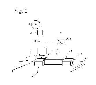
Figure 1 shows a simplified schematic of a print head, staging surface and a
printed object
according to an embodiment of the present invention;
Figure 2 shows a plan view of first and second islands of printed material and
an
intermediate region printed therebetween along a first path;
Figure 3 shows a top view of the object of Figure 1;
Figure 4 shows a plan view of first and second islands of printed material and
an
intermediate region printed therebetween along a second path; and
Figure 5 shows a schematic of a method according to an embodiment of the
present
invention.
Description of embodiments
Figure 1 shows a simplified schematic of a printer assembly for printing a
three-dimensional
object, according to an embodiment of the present invention. As shown in
Figure 1, the three-
dimensional object 1 comprises at least one layer formed of a first region 2
of printed material and
a second region 4 of printed material. The first region 2 is separated from
the second region 4 by a
space in which there is formed at least one layer formed of an intermediate
region 6.
The printer assembly comprises a print nozzle 12 configured to deliver a
flowable print
material and a staging surface 8 onto which successive layers 10 of print
material can be printed to
form the three-dimensional object. A control system 14 is provided to control
movement of the print
nozzle 12 relative to the staging surface 8 and is configured to move the
nozzle during a printing
process. In this example, the printer assembly is an FDM print assembly
wherein a filament 11 is
fed by means of a feeder unit 15. In this example the filament 11 is stored on
a spool 13, see Figure
1. The control system 14 is configured to control the feed unit 15 so as to
control the feeding of the
filament 11 to the print nozzle 12.
Alternatively, the printer assembly may be a syringe based print assembly
comprising a
filled syringe volume. In either case, the present invention can reduce or
eliminate the quality issues
associated with nozzle ooze on the end product.
Referring now to Figure 2, the control system 14 is configured to control the
movement of
the print nozzle 12 in at least three phases, also referred to as printing
steps.
CA 03105669 2021-01-05
WO 2020/022874 PCT/NL2019/050427
During a first printing step, the control system 14 moves the nozzle 12 for
printing the first
region 2 by delivering a flowable print material from the print nozzle 12. The
print nozzle 12 travels
relative to the staging surface 8 during the first printing step at a first
print speed V1.
During an intermediate printing step, the control system 14 moves the nozzle
12 for printing
5 the intermediate region 6 by delivering a flowable print material from
the print nozzle. During this
step, the print nozzle 12 travels relative to the staging surface 8 and
delivers flowable print material
over a first travel distance D1 at a first travel speed Si, over a second
travel distance (D2) at a
second travel speed S2, and over a third travel distance D3 at a third travel
speed S3.
During a second printing step, the control unit 14 moves the nozzle 12 for
printing the
second region 4 by delivering a flowable print material from the print nozzle.
During this step, the
print nozzle 12 travels relative to the staging surface 8 during the second
printing step at a second
print speed V2. To provide a small amount of extruded material in the
intermediate region adjacent
to the first and second islands, each of the first travel speed Si and the
third travel speed S3 is
greater than the first print speed V1, the second travel speed S2 and the
second print speed V2.
By moving the print nozzle very quickly for only a short travel distance (D1
and D3), the back
pressure from the printed surface remains constant throughout the print
process, thus maintaining
a constant pressure within the nozzle and an even print track. This allows for
tidier edges and an
improved end product.
The steps of a method according to an embodiment of the present invention are
shown in
Figure 5. As shown in Figure 5, a method of printing a three-dimensional
object comprises a first
step 101 of: printing a first region 2 during a first printing phase by
delivering a flowable print material
from a print nozzle travelling relative to a staging surface 8 at a first
print speed V1. In a second
(intermediate printing) step 102, the method comprises b) printing an
intermediate region 6 (in a
space between the first region 2 and the second region 4) by delivering a
flowable print material
from the print nozzle in three phases. In a first phase 102a the nozzle 12
travels relative to the
staging surface 8 to deliver flowable print material over a first travel
distance D1 at a first travel
speed Si. During a second phase 102b, the nozzle 12 moves over a second travel
distance D2 at
a second travel speed S2. During a third phase 102c, the nozzle 12 moves over
and a third travel
distance D3 at a third travel speed S3. In a third step 103, the method
involves: printing a second
region 4 by delivering a flowable print material from the print nozzle 12,
which travels relative to the
staging surface 8 at a second print speed V2. To ensure only a small amount of
extruded material
in the intermediate region adjacent to the first and second islands, each of
the first travel speed Si
and the third travel speed S3 is greater than the first print speed V1, the
second travel speed S2
and the second print speed V2.
As shown in Figure 2, the first distance D1 is immediate adjacent the first
region 2 and the
second distance D3 is immediately adjacent the second region 4. The second
distance D2 connects
the first and third distances D1 and D3. The skilled person will appreciate
that the travel speeds Si,
S2, S3 of the nozzle do not need to be constant over the entire travel
distance D1, D2, D3. However,
there must be an acceleration of the nozzle between V1 and Si and S2 and S3.
There must also
be a deceleration of the nozzle between S3 and V2.
CA 03105669 2021-01-05
WO 2020/022874 PCT/NL2019/050427
6
By providing a method and apparatus that include first and third travel speeds
that are
greater than the first and second print speeds and the second travel speed,
the print head
accelerates away from/towards the printed islands in the region immediately
adjacent to the printed
islands of material. This acceleration away from/towards the islands produces
a final product in
which the intermediate portion is unconnected to the first and second islands,
or is connected only
by a thin connection portion, which can easily be removed from the main
islands. Figure 3 shows a
top view of the object 1 of Figure 1. As can be seen, the object comprises the
first region 2, the
second region 4 and the intermediate region 6. The intermediate region 6
comprises an
intermediate portion 61 and two connection portions 62, 63 connecting the
intermediate portion 61
to the printed islands 2, 4 respectively. As can be seen from Figure 3, the
connection portions 62,
63 are relatively thin. The first connection portion 62 has a length of D1,
the intermediate portion 61
has a length of D2, and the second connection portion 63 has a length of D3.
The first print speed V1 may be equal to the second print speed V2, providing
a constant
print speed for all sections of the final object. However, the skilled person
will understand that
different print speeds can be used for different portions of the final object.
Therefore, the first print
speed V1 and the second print speed V2 can be different.
In an embodiment, each of the first travel speed Si and the third travel speed
S3 is relatively
high as compared to the first print speed V1, the second travel speed S2 and
the second print speed
V2. A relatively high speed of the print head at either end of the wall means
that the intermediate
region contains relatively thin outer ends so that the intermediate region can
be easily broken away
from the islands after the object has been completed.
The first travel speed Si and the third travel speed S3 can be equal. This
provides a
substantially uniform "fast speed" for creating the discontinuity between the
intermediate portion 6
and the printed islands 2, 4.
The second travel speed S2 can be equal to one or both of the first and second
print speeds
V1, V2. Where the first and second print speeds are the same as each other,
and the first and third
travel speeds are the same as each other, the system requires only two
operating speeds:
Vi =V2=52 and S1=S3. However, the skilled person will appreciate that each of
V1, V2, Si, S2 and
S3 can be different.
In an embodiment of the invention, the first and second print speeds V1, V2
are greater
than the second travel speed S2. Since the intermediate region consists of a
single line structure,
a lower travel speed is preferred to increase stability of the structure.
As mentioned above, the first and third travel speeds Si, S3 used during the
printing of the
first and second connection portions 62, 63, are greater that the first and
second print speeds V1,
V2. A relatively short, fast jump (compared to the first and second print
speeds) combined with the
viscosity of the flowable material means that the pressure drop within the
nozzle is minimised. The
skilled person will appreciate that in order to achieve a minimal drop in
pressure for lower viscosity
print material, the travel speeds can be increased. Although it is possible to
vary the pressure to
compensate during speed changes, without the backpressure, control of the
pressure within the
nozzle is challenging and variations in track width and oozing may result.
CA 03105669 2021-01-05
WO 2020/022874 PCT/NL2019/050427
7
Advantageously, the intermediate region can be self-supporting, so that it
does not fall
during the printing process. In some embodiment, a self-supporting
intermediate region can be
provided by printing the intermediate region along a meandering path, e.g. a
sinusoidal, zigzag,
square wave shaped path or the like. An example of such an embodiment is shown
in Figure 4. An
advantage of a meandering path is that the resulting intermediate portion is
more stable as
compared to a straight wall.
In an embodiment, the intermediate region 6 leaves the first region 2 having a
departure
angle a with the angle a being smaller than 90 degrees, preferably smaller
than 45 degrees. The
angle a is defined as the angle between the tangent line on the circumference
of the first region at
the transition point and the initial direction of the intermediate region,
i.e. of the intermediate path.
An advantage of having a departure angle smaller than 90 degrees is that the
nozzle movement
can be more fluent and does not face abrupt direction changes. If the printing
path of the nozzle is
more fluent, the flow of print material can be more fluent which results in
less fluctuations in the
trace width. Similarly, an angle of entry 13 at the second portion 4 may have
a value less than 90
degrees, and preferably less than 45 degrees.
The precise print and travel speeds selected for systems and methods according
to the
invention can be chosen depending on the configuration of the print head
(nozzle diameter, flow
rate, etc.) and the flowable material selected.
In one exemplary embodiment, the first and third travel speeds 51 and S3 are
at least
100mm/s. For example, the first and third travel speeds Si and S3 can be
between 100 and
150mm/s, although travel speeds of up to 500mm/s are possible and have been
shown to be
effective in tests of the present invention. The present invention is also
applicable to assemblies
having travel speeds of over 500mrn/s. Depending on the system, the first and
third travel speeds
can be at least 200 mm/s; at least 300 mm/s, or at least 400 mm/s.
The first and second print speeds V1, V2 can be at least 20 mm/s. For example,
the first
and second print speeds can be between 20 and 60 mm/s. The present invention
is also applicable
to assembling providing print speeds of over 60 mm/s.
The second travel speed S2 can be at least 20 mm/s (e.g. between 20 and 50
mm/s). The
present invention is also applicable to assemblies providing travel speeds of
over 50 mm/s.
To prevent movement of printed artefacts (first and second islands 2, 4), the
control system
14 can be configured to limited acceleration (and deceleration) of the print
head to a predetermined
threshold. For example, systems and methods according to the present invention
can limit
acceleration from the first print speed Vito the first travel speed Si.
Acceleration from the second
travel speed S2 to the third travel speed S3 can also be limited, as can
deceleration from the first
travel speed Si to the second travel speed S2 and deceleration from the third
travel speed S3 to
the second print speed V2.
The distances D1, D2 and D3 can be chosen depending on the object to be
printed and the
rheology of the flowable material to be printed. In any event, to ensure that
the pressure drop in the
nozzle 12 is minimised during the relatively high speed travel across
distances Di and D3, D2 is
CA 03105669 2021-01-05
WO 2020/022874 PCT/NL2019/050427
8
larger than D1 and D3. In exemplary embodiments, D1 and D3 are between 0.1 and
5mm, between
0.3 and 4mm, or between 0.5 and 3mm.
In the above the intermediate printing step is defined as a separate printing
step. However
it should be noted that not only 'during' the intermediate printing step there
is no interruption of the
flow of the print material to the nozzle, but also at the transitions between
this intermediate printing
step and the other two printing steps (i.e. the first and second printing
step). This means that during
the printing of one layer, the is no interruption of the flow of print
material to the nozzle. One should
note that the feeding of the filament may vary but never to that extent that
the flow of material is
interrupted during the printing of the first, second and intermediate region.
In the examples above, only the printing of the perimeters of the regions 2
and 4 are shown.
It is clear to the skilled person that the regions 2 and 4 may be filled with
infill to produce solid, or
at least partly filled, objects.
The flowable material extruded through the nozzle 12 can comprise a flexible
polymer, such
as a thermoplastic polyurethane. The present invention solves many of the ooze
management
problems associated with this type of flexible material because the pressure
within the print nozzle
is maintained at a constant level throughout the print process.
Advantageously, systems and methods according to the present invention can
keep the
distance between the nozzle and the previously printed layer constant. In
other words, the nozzle
does not retract to travel the distance between islands 2 and 4. This
circumvents the disadvantages
.. of retraction type print heads, which often lead to poor object
construction due to ooze of flowable
material.
Moreover, systems and method according to the present invention can be
configured such
that the flowable material flows at a constant rate from the nozzle 12. This
simplifies the flow control
within the printer and prevents the poor build quality that can occur as a
result of varying pressure
within the print head (including the extrusion channels and the nozzle 12).
The skilled person will understand that the present invention has been
described with
reference to a number of illustrative, exemplary embodiments and that
modifications may be made
to these embodiments without departing from the scope of the invention.