Note: Descriptions are shown in the official language in which they were submitted.
AUTOMATED CHICKEN DEBONER SYSTEM AND METHOD
CROSS-REFERENCE TO RELATED APPLICATIONS
[0001] Not applicable
STATEMENT REGARDING FEDERALLY SPONSORED RESEARCH OR
DEVELOPMENT
[0002] Not applicable
BACKGROUND OF THE INVENTION
[0003] The present invention relates to an automated system and method for
deboning the front-half of a chicken. In a typical poultry processing plant,
chicken is
processed into two-halves. The front-half, which includes the wings, breast
meat, and
tenders of the chicken, is cut from the legs and thighs. The front-half and
back-half
proceed to different locations in the processing plant to be further
processed. Poultry
processing plants use one of two options (or sometimes a combination of both)
to
process the front-half of the chicken: manual processing or automated
processing. In a
manual processing line, people cut and pull the meat from the chicken carcass
by hand
using handheld knives for some of the processes. In an automated processing
line,
machinery is used to cut and separate the meat from the chicken carcass. The
goal of
both methods is to remove the highest percentage of meat from the chicken
carcass
quickly and consistently. There are benefits and drawbacks for both manual and
automated processing.
[0004] For manual deboning, the poultry processing plant must hire 8-12
workers to operate one processing line (i.e., cone line). Plants typically
have multiple
1
Date Recue/Date Received 2021-01-18
cone lines. Most processing plants also utilize two shifts which doubles the
number of
workers required for manual deboning. Manual deboning is a tedious and taxing
job for
these workers. Workers perform the same repetitive action for each chicken
they
process. Performing the same motions to process the chickens hour after hour
can
lead to injuries and unpleasant work conditions for the workers. This leads to
difficulties
maintaining staffing and leaves many plants under-staffed for these manual
deboning
lines.
[0005] When a processing plant implements automated deboning, the workers
needed to process the same number of birds per minute is greatly reduced. But
automated deboning machines typically struggle with achieving the same levels
of yield
as manual deboning. The machines are unable to remove the meat from the
chickens
as efficiently. The meat that is left behind on the chicken carcass results in
huge profit
losses as this meat is either thrown away or sold at lower prices with the
carcass.
[0006] It would therefore be desirable to develop an automated deboner system
to process the front-half of a chicken to reduce the number of workers
operating per
cone line, achieve a comparable or better yield, and reduce the footprint of
the
processing area in the plant.
BRIEF SUMMARY OF THE INVENTION
[0007] The present invention is directed to an automated chicken deboner
system and method. The deboner system utilizes a conveyor system to process
and
move the front-half of the chicken through the different deboning stations
attached along
a frame. The system includes the following stations: (1) a loading station
where the bird
is placed on a cone; (2) a press station to align the front half of the
chicken on the cone;
2
Date Recue/Date Received 2021-01-18
(3) a skin cutter station to cut the skin and fat located at the base of the
neck of the bird;
(4) a wing cutter station to remove the wings from the bird; (5) a scapula
cutter station to
separate the breast meat from the scapula; (6) a wishbone cutter station to
separate the
breast meat from the wishbone; (7) a breast plow station to separate the
breast meat
from the ribs of the bird; (8) a wishbone paddle station to further separate
the breast
meat from the wishbone; (9) a breast removal station to completely remove the
breast
meat from the bird; and (10) a tender cutter station to remove the two tenders
from the
bird.
[0008] These and other features, objects and advantages of the present
invention will become better understood from a consideration of the following
detailed
description of the preferred embodiments and appended claims in conjunction
with the
drawings as described following:
BRIEF DESCRIPTION OF THE DRAWINGS
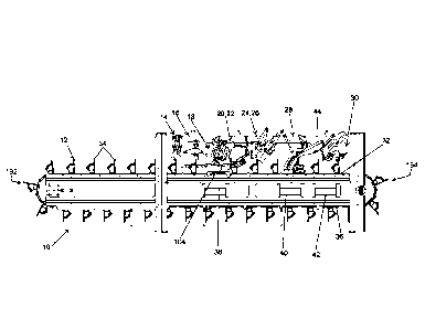
[0009] FIG. 1 is a side view of all of the stations of the deboner system of
the
present invention.
[0010] FIG. 2A is a front view of a whole front-half. FIG. 2B is a side view
of a
whole front-half.
[0011] FIG. 3A is a front view of a front-half with the breast meat and wings
removed. FIG. 3B is a side view of a front-half with the breast meat and wings
removed.
[0012] FIG. 4A is a perspective view of the cone of the deboner system of the
present invention. FIG. 4B is a side view of the cone of the deboner system of
the
present invention. FIG. 4C is a back view of the cone of the deboner system of
the
3
Date Recue/Date Received 2021-01-18
present invention. FIG. 4D is a top view of the cone of the deboner system of
the
present invention.
[0013] FIG. 5A is a top view of the conveyor belt with cones of the deboner
system of the present invention. FIG. 5B is a side view of the conveyor belt
with cones
of the deboner system of the present invention.
[0014] FIG. 6A is a perspective view of the first press of the press station
of the
present invention from the inlet end of the deboner system. FIG. 6B is a
perspective
view of the second press of the press station of the present invention from
inlet end of
the deboner system and with the first press omitted.
[0015] FIG. 7A is a side view of the press station of the present invention
with
the press station in the resting position. FIG. 7B is a side view of the press
station of
the present invention transitioning from the resting position to the actuated
position.
FIG. 7C is a side view of the press station of the press invention in the
fully actuated
position.
[0016] FIG. 8A is a perspective view of the skin cutter station of the present
invention from the outlet end of the deboner system prior to the cut being
made. FIG.
8B is a perspective view of the skin cutter station of the present invention
from the outlet
end of the deboner system while the cut is being made. FIG. 8C is a
perspective view
of the skin cutter station of the present invention from the outlet end of the
deboner
system after the cut has been made.
[0017] FIG. 9A is a side view of the skin cutter station of the present
invention
prior to the cut being made. FIG. 9B is a side view of the skin cutter station
of the
present invention while the cut is being made.
4
Date Recue/Date Received 2021-01-18
[0018] FIG. 10 is a perspective view of the wing cutter station of the present
invention from the outlet end of the deboner system.
[0019] FIG. 11A-11F are perspective views of the wing cutter station of the
present invention from the outlet end of the deboner system in six sequential
steps
starting with FIG. 11A and ending with FIG. 11F. FIGS. 11A-11E show one side
of the
wing cutter station, while FIG. 11F shows both sides of the wing cutter
station. FIG.
11A shows one shoulder clamp in the up position and one blade in the up
position, FIG.
11B shows one shoulder clamp in the down position and one blade in the up
position,
FIG. 11C shows one shoulder clamp in the down position and one blade moving
down,
FIG. 11D shows one shoulder clamp in the down position and one blade moving
down,
FIG. 11E shows one shoulder clamp in the down position and one blade moving
down,
and FIG. 11F shows both shoulder clamps in the down position and both blades
in the
down position after the wings were removed from the front-half.
[0020] FIGS. 12A-12F are side views of the wing cutter station of the present
invention in six sequential steps starting with FIG. 12A and ending with FIG.
12F.
[0021] FIG. 13A is a perspective view of the left scapula cutter of the
scapula
cutter station of the present invention. FIG. 13B is a perspective view of the
right
scapula cutter of the scapula cutter station of the present invention.
[0022] FIGS. 14A-14F are perspective views of the scapula cutter station of
the
present invention from the outlet end of the deboner system in six sequential
steps
starting with FIG. 14A and ending with FIG. 14F. FIG. 14A shows the scapula
blade in
the out and up positions, FIG. 14B shows scapula blade in the in and up
positions, FIG.
14C shows the scapula blade in the in position and moving downward, FIG. 14D
shows
Date Recue/Date Received 2021-01-18
the scapula blade in the in and down positions, FIG. 14E shows the scapula
blade in the
out and down positions after the cuts have been made, and FIG. 14F shows the
scapula
blade in the out and up positions after the cuts have been made.
[0023] FIGS. 15A-15F are side views of the scapula cutter station of the
present
invention in six sequential steps starting with FIG. 15A and ending with FIG.
15F. FIG.
15A shows the scapula blade in the out and up positions, FIG. 15B shows
scapula
blade in the in and up positions, FIG. 15C shows the scapula blade in the in
position
and moving downward, FIG. 15D shows the scapula blade in the in and down
positions,
FIG. 15E shows the scapula blade in the out and down positions after the cuts
have
been made, and FIG. 15F shows the scapula blade in the out and up positions
after the
cuts have been made.
[0024] FIG. 16 is a side view of the wishbone cutter station of the present
invention.
[0025] FIGS. 17A-17D are side view of the wishbone cutter station of the
present
invention in four sequential steps starting with FIG. 17A and ending with FIG.
17D. FIG.
17A shows the wishbone blade in the up and forward positions, FIG. 17B shows
the
wishbone blade in the down and forward positions, FIG. 17C shows the wishbone
blade
in the down and backward positions, and FIG. 17D shows the wishbone blade in
the up
and forward positions after the cut has been made. The forward position refers
to the
position towards the outlet end of the deboner system, while the backward
position
refers to the position towards the inlet end of the deboner system.
[0026] FIGS. 18A-18B are top views of the wishbone blade of the wishbone
cutter station of the present invention. FIG. 18A shows the wishbone blade in
the down
6
Date Recue/Date Received 2021-01-18
position and sitting on the shoulder knuckles before making the cut. FIG. 18B
shows a
portion of the wishbone blade in the bird after making the cut.
[0027] FIGS. 19A-19D are side views of the breast plow station of the present
invention in four sequential steps starting with FIG. 19A and ending with FIG.
19D. FIG.
19A shows the plow plates in the out and up positions and the shoulder clamps
in the
up position, FIG. 19B shows the plow plates in the in position and going down
and the
shoulder clamps in the down position, FIG. 19C shows the plow plates in the in
and
down position and the shoulder clamps in the down positions, and FIG. 19D
shows the
plow plates in the out and up positions and the shoulder clamps in the up
position after
the breast meat has been disconnected from the ribs of the bird.
[0028] FIGS. 20A-20D are perspective views of the breast plow station of the
present invention from the outlet end of the deboner system in four sequential
steps
starting with FIG. 20A and ending with FIG. 20D. FIG. 20A shows the plow
plates in the
out and up positions and the shoulder clamps in the up position, FIG. 20B
shows the
plow plates in the in and up positions and the shoulder clamps in the down
position,
FIG. 20C shows the plow plates in the in and down positions and the shoulder
clamps in
the down position, and FIG. 20D shows the plow plates in the out and up
positions and
the shoulder clamps in the up position after the breast meat has been
disconnected
from the ribs of the bird.
[0029] FIGS. 21A-21D are side views of the wishbone paddle station of the
present invention in four sequential steps starting with FIG. 21A and ending
with FIG.
21D. FIG. 21A shows the wishbone paddle in the up and retracted positions,
FIG. 21B
shows the wishbone paddle is the down and retracted positions, FIG. 21C shows
the
7
Date Recue/Date Received 2021-01-18
wishbone paddle is in the down and extended positions, and FIG. 21D shows the
wishbone paddle is in the up and retracted positions after the wishbone paddle
has
further disconnected the breast meat from the wishbone.
[0030] FIG. 22A is a perspective view of the wishbone paddle station of the
present invention from the inlet end of the deboner system with the wishbone
paddle in
the up position. FIG. 22B is a perspective view of the wishbone paddle station
of the
present invention from the inlet end of the deboner system with the wishbone
paddle in
the up position and the breast meat omitted.
[0031] FIG. 23A is a perspective view of the wishbone paddle station of the
present invention from the inlet end of the deboner system with the wishbone
paddle in
the down position. FIG. 23B is a perspective view of the wishbone paddle
station of the
present invention from the inlet end of the deboner system with the wishbone
paddle in
the down position and the breast meat omitted.
[0032] FIGS. 24A-24F are side views of the breast removal station of the
present
invention in six sequential steps starting with FIG. 24A and ending with FIG.
24F. FIG.
24A shows the shoulder clamps in the up position and the roller in the up
position. FIG.
24B shows the shoulder clamps in the down position and the roller in the up
position.
FIGS. 24C-24D show the shoulder clamps in the down position and the roller
going
down. FIG. 24E shows the shoulder clamps in the down position and the roller
in the
down position. FIG. 24F shows the shoulder clamps in the up position and the
roller in
the up position after the breast meat has been completely removed from the
bird.
[0033] FIG. 25A is a perspective view of the roller of the breast removal
station
of the present invention from the inlet end of the deboner system. FIG. 25B is
a
8
Date Recue/Date Received 2021-01-18
perspective view of the roller of the breast removal station of the present
invention from
inlet end of the deboner system with the breast meat omitted.
[0034] FIGS. 26A-26C are top views of the breast paddles of the present
invention in three sequential steps starting with FIG. 26A and ending with
FIG. 26C.
FIG. 26A shows the cone aligned with the paddles, the paddles open, and the
breast
meat attached to the bottom of the bird. FIG. 26B shows the cone aligned with
the
paddles, the paddles closed, and the breast meat attached to the bottom of the
bird.
FIG. 26C shows the cone moved past the paddles, the paddles closed, and the
breast
meat detached from the bird and held between the paddles.
[0035] FIGS. 27A-27C are side views of the breast paddles of the present
invention in three sequential steps starting with FIG. 27A and ending with
FIG. 27C.
FIG. 27A shows the cone aligned with the paddles, the paddles open, and the
breast
meat attached to the bottom of the bird. FIG. 27B shows the cone aligned with
the
paddles, the paddles closed, and the breast meat attached to the bottom of the
bird.
FIG. 27C shows the cone moved past the paddles, the paddles closed, and the
breast
meat detached from the bird and held between the paddles.
[0036] FIGS. 28A-28F are perspective views of the tender cutter station of the
present invention from the inlet end of the deboner system in six sequential
steps
starting with FIG. 28A and ending with FIG. 28F. FIG. 28A shows the shoulder
clamp
and the spreader in the down position with the blades in the out and up
positions, FIG.
28B shows the shoulder clamp and spreader in the down position with the blades
going
in and in the up position, FIG. 28C shows the shoulder clamp and spreader in
the down
position with the blades in the in and up positions, FIG. 28D shows the
shoulder clamp
9
Date Recue/Date Received 2021-01-18
and spreader in the down position with the blades in the in position and going
down,
FIG. 28E shows the shoulder clamp and spreader in the down position and the
blades
in the in position and going down, and FIG. 28F shows the shoulder clamp and
spreader in the down position and the blades in the in and down positions
after the
tenders have been completely removed from the carcass.
[0037] FIG. 29 is a side view of the tender shoulder clamp and tender spreader
positioned on the front-half with the blades of the tender cutter station
omitted.
DETAILED DESCRIPTION OF THE INVENTION
[0038] With reference to FIGS. 1-29, the preferred embodiments of the present
invention may be described. The present invention is directed to an automated
chicken
deboner system and method to remove the wings, breast meat, and tenders from
the
carcass of the chicken. The deboner system 10 utilizes a conveyor system to
process
and move the front-half of the chicken (also referred to herein as a "bird" or
a "carcass")
through the different deboning stations attached along a frame 44. Cones 34
are
mounted to the conveyor belt 32 at equal distances from one another and the
front-half
of the bird 46 is held on the cone 34 as it is deboned. As described
individually below,
the deboner system 10 includes the following stations: (1) a loading station
12 where
the bird is placed on a cone; (2) a press station 14 to align the front-half
on the cone; (3)
a skin cutter station 16 to cut the skin and fat located at the base of the
neck of the bird;
(4) a wing cutter station 18 to remove the wings from the bird; (5) a scapula
cutter
station 20 to separate the breast meat from the scapula; (6) a wishbone cutter
station
22 to separate the breast meat from the wishbone; (7) a breast plow station 24
to
separate the breast meat from the ribs of the bird; (8) a wishbone paddle
station 26 to
Date Recue/Date Received 2021-01-18
further separate the breast meat from the wishbone; (9) a breast removal
station 28 to
completely remove the breast meat from the bird; and (10) a tender cutter
station 30 to
remove the two tenders from the bird.
[0039] In the first preferred embodiment, these different stations are fixed
and
mounted to a stationary frame 44. Each of stations (2)-(10) listed above are
bolted to
the frame 44. After the bird 46 is loaded onto a cone 34, the cone 34 then
indexes
forward through the system and stops at each stationary station to cut and/or
remove a
different part of meat from the front-half 46. In the second preferred
embodiment, all of
the stations are mounted to an upper frame 44 that indexes forward in unison
with the
conveyor belt 32. After the bird is loaded onto a cone, the belt 32
continuously moves
the cone 34 forward and the upper frame 44 indexes forward with the belt 32 as
each
station performs its task. In this embodiment, once the conveyor belt 32 moved
the
cones underneath the stations, the upper frame 44 is synchronized and thus
moves at
the same speed as the conveyor belt 32. The stations are mounted to the frame
44
such that they all reach the synchronization point at the same time. This
allows the
stations to perform their tasks as if the birds on the cones were not moving
underneath
them. Once the stations have completed their task, the upper frame 44 quickly
resets
so it can index forward again with the following cone 34. The meat is cut and
removed
from the front-half 46 in the same manner in both embodiments. The first
embodiment
just utilizes an indexing conveyor belt and fixed frame with stations, while
the second
embodiment uses a continuously moving belt with an indexing frame with
stations. The
first embodiment in which the upper frame 44 is fixed is the preferred
embodiment in
11
Date Recue/Date Received 2021-01-18
part because the upper frame 44 acts as brace and stabilizes the entire system
10 in
that embodiment.
[0040] Loading Station: The deboning process begins with the front-half 46
being loaded onto a cone (or support) 34 that is mounted to the conveyor belt
32. The
loading station 12 of the system is the portion of the conveyor belt 32
holding vertically
oriented cones that have yet to reach the press station 14. Because the
conveyor belt
32 is moving, the portion of the conveyor belt 32 in the loading station
changes. The
loading station is located at the inlet end 192 of the system 10. After the
bird 46 moves
through all of the stations at the outlet end 194 of the system, the cone 34
on the
conveyor belt 32 moves underneath the frame 44 and is returned to the loading
station
12. The return portion 36 of the conveyor belt 32 is shown in FIG. 1.
[0041] The bird has an empty inner cavity after evisceration and after the
back-
half of the chicken is removed. During loading, the cone 34 is pushed into the
inner
cavity as the bird is slid over the top of the cone. The cone is sized to
substantially fill
the inner cavity of the bird. The bird is loaded on the cone 34 such that the
breast meat
of the bird is facing away from the first cutting station or towards the inlet
end of the
deboner system. The back surface of the cone (i.e., the surface of the cone
facing the
outlet end of the deboner system) includes an oval opening, as shown in FIG.
4A and
FIG. 4C. There is a bulge directly behind the neck of the bird inside the
cavity of the
bird. There is also a bulge inside the cavity where the ribs of the bird come
together.
Those bulges in the cavity of the bird are positioned inside the opening of
the cone
when the bird is properly positioned on the cone. The structure of the cone is
critical to
the effectiveness of the deboner system because the cone structure ensures
that the
12
Date Recue/Date Received 2021-01-18
bird is positioned correctly as the bird moves through each station of the
deboner
system. The bird has two shoulder knuckles 48 (one on each side) where the
wings 50
are attached. It is critical that these knuckles are set at the correct height
and width on
the cone 34, regardless of the size variances of the birds. The deboner system
utilizes
these shoulder knuckle contact points as zeroing sites throughout the system
to allow
correct positioning of each station as they perform their task. As shown in
FIGS. 4A-4D,
there is a shelf 52 on each side of the upper portion of the cone 34 that the
shoulder
knuckle 48 sits on to set the height of the knuckle 48. In the upper center of
the cone
34 is a protrusion 54 that sits between the shoulder knuckles 48 and spreads
them to
the same width on both small and large birds. The body 56 (also referred to as
the
lower portion) of the cone 34 slopes downward and outward from the base of the
protrusion 54 and serves as a support for the bird under the breast meat. The
body 56
then segues downward and inward to the base of the cone, as shown in FIG. 4B.
The
sides of the cone extend downward and slightly outward from each of the
shelves 52.
This cone structure allows a large size range of front-halves to be positioned
and
deboned accurately and precisely on the same machine.
[0042] The conveyor belt 32 (also referred to as the "primary conveyor belt")
is a
continuous belt which consists of cone plates 58 that are linked together, as
shown in
FIGS. 5A-5B. One cone plate 58 is connected to the next cone plate 58 via two
links 60
on the outside of the cone plate 58. This leaves room for a large gap 62
between cone
plates. The meat that is removed from the bird as it moves through the deboner
system
(except the wings) passes through the gap 62 between the cone plates 58. Meat
that
falls through the top section of the belt lands onto a transfer slide or
conveyor system
13
Date Recue/Date Received 2021-01-18
that runs underneath the primary conveyor belt. This transfer slide or
conveyor system
catches the removed meat before the meat reaches the lower return part of the
primary
conveyor belt and then transports the removed meat for further processing. For
example, the deboner system 10 may include a breast transfer conveyor 40 that
transports the removed breast meat from the deboner system 10. Similarly, the
system
may also include tender transfer conveyor 42 that transports the removed
tenders
from the deboner system 10. In one embodiment, the breast transfer conveyor 40
and
tender transfer conveyor 42 extend through the frame 44 of the deboner system
10, as
shown in FIG. 1. This belt design with gaps eliminates the need for a separate
mechanism to remove the removed meat from the deboner system.
[0043] Press Station: Once the front half 46 is loaded onto the cone 34, the
conveyor 32 indexes forward to the first automated station: the press station
14. A first
(or forward) press 64 pushes the front-half 46 forward onto the cone 34. A
second (or
downward) press 66 then pushes downward on both shoulder joints
simultaneously.
The first press 64 ensures that the shoulder knuckles 48 are seated in the
correct
location as the second press 66 pushes the front-half 46 down until the
shoulder
knuckles 48 are resting on the shelf sections 52 that are cut into each side
of the cone
34. As the front-half 46 is pressed down, the protrusion 54 in the center of
the cone 34
spreads the shoulder knuckles 48 to the necessary position for the remaining
stations.
[0044] As shown in FIGS. 6A-6B, the first press 64 preferably includes a flat
front plate for contacting the bird. The first press 64 preferably contacts
the upper
portion of the breast meat 68 of the bird 46 and pushes the bird forward on
the cone 34.
The second press 66 preferably includes two arms 80 for contacting opposite
sides of
14
Date Recue/Date Received 2021-01-18
the bird. The second press 66 contacts the breast meat 68 of the bird 46 above
the
shoulder knuckles 48 and pushes downward to seat the bird on the cone 34. In
one
embodiment, the two arms 80 are separate pieces that are connected as shown in
FIG.
6B. In an alternative embodiment, a single plate includes the two arms 80. In
this
alternative embodiment, the two arms 80 are separated by a notch for clearance
of the
bird neck 84. The arms 80 have a slight bevel to hold the shoulder knuckles
inward so
that they do not spread too much with the downward force of the second press
66.
[0045] As shown in FIGS. 7A-7C, the press station 14 includes a first (or
forward) press actuator 70 and a second (or downward) press actuator 72 that
move the
presses 64, 66. The first press 64 is slidable connected to the second press
66 via a
pivot rod 78. In the resting position, the first press 64 is positioned in the
bottom of
channel 76 of second press 66. As shown in FIG. 7B, once the presses 64, 66
are
actuated by the press actuators 70, 72, the first press 64 swings downward at
pivot
point 74 and the second press 66 moves straight downward. When fully actuated,
the
first press 64 is positioned in the top of the channel 76 of second press 66,
as shown in
FIG. 7C.
[0046] Skin Cutter Station: From the press station 14, the front-half 46
indexes
to the skin cutter station 16. Skin and fat are usually found in the area at
the base of the
neck 84 above the wishbone area of the bird. A flat cutting blade 82 is
mounted on an
arm that is connected to a skin cutter actuator 90. The skin cutter actuator
90 is
mounted to the frame 44 above the primary conveyor belt 32. When activated,
the
cutting blade 82 swings perpendicular to the direction of the conveyor belt 32
and
makes a cut 88 through the skin and fat 86 located at the base of the neck
above the
Date Recue/Date Received 2021-01-18
wishbone area. When the bird is positioned on the cone 34, the neck 84 of the
bird 46
folds over the back of the bird. The skin cutter does not remove any meat.
Instead, the
skin cutter serves to sever these connection points to help to prepare the
bird for further
processing down the line. FIGS. 8A-8C show the skin cutter station and the
bird before
the cut is made (FIG. 8A), while the cut is being made (FIG. 8B), and after
the cut is
made (FIG. 8C). FIG. 9A shows the skin cutter station and the bird before the
cut is
made, while FIG. 9B shows the skin cutter station and the bird while the cut
is being
made.
[0047] Wing Cutter Station: From the skin cutter station, the front-half 46
indexes to the wing cutter station 18. This station includes four critical
components: two
shoulder clamps 100, two wing cutter blades 102, two fixed guide plates 104,
and two
wing guides 106. The shoulder clamps 100 press down from above the bird and
clamp
onto the shoulder knuckles 48. This locks the bird into place and keeps it
from moving
during the wing cutting process. This aids in the precision of the wing cut
and ensures
the cut to be in the same place every time. While the shoulder clamps 100 are
preferably separate plates, they are actuated together with a single actuator
198.
[0048] Each of the wing cutting blades 102 is a cylindrical blade that is
hollow on
the inside. This provides clearance for the wing to come up inside as the
blade cuts
around the wing knuckle 110 to disconnect it from the bird. Each rotating
blade 102 is
connected to two linkages or mounting arms 112 that are connected to an
actuator 114.
The actuators 114 are connected to the upper frame 44 and create the movement
of the
linkages 112 and the blades 102. The actuator 114 moves the blade down into a
position where the edge of the blade 102 is between the wing knuckle 110 and
the
16
Date Recue/Date Received 2021-01-18
shoulder knuckle 48. The inside of the wing blade cutting edge is beveled to
allow the
wing bones to slide away from the cutting edge as the blade is actuated
downwards
while making its cut. The beveled edge aids in controlling the cut to only
cutting flesh
and connective tissue in the area.
[0049] The fixed guide plates 104 keep the wings from resting too close to the
body of the front-half 46 and provide support for the wing when the blade 102
contacts
it. The guide plates 104 are connected to the side of the conveyor belt 32. As
the cone
34 moves into the wing cutter station 18, the fixed guide plates 104 slide
between the
wings 50 and the front-half 46 and slightly lift the wings 50. The leading
edge of the
guide plates 104 has a tab 108 that is bent slightly inward and downward. The
tab 108
catches under the wing and the wing then slides over the top of the guide
plate 104.
This ensures that the guide plates 104 hold the wings in the correct position
before
cutting. Because the guide plates 104 are angled downward and outward from the
conveyor belt 32 as shown in FIG. 10, the guide plate 104 holds the wing
steady and
provides support underneath the wing 50 as the blade 02 cuts through the joint
area
and presses down.
[0050] Wing guide arms 106 work in combination with the fixed guide plates
104.
The wing guides 106 are attached to the same linkage as the wing cutter blades
102
and therefore they all move together. As each wing cutter blade 102 is
actuated down
and cuts through the joint, the wing guide 106 moves with the blade 102 and
sandwiches the wing 50 between the wing guide 106 and the guide plate 104, as
shown
in FIGS. 11A-11F. This holds the wing in place and keeps it from rotating
while the cut
is made. If the wing manages to rotate, the possibility of cutting through
bone, skin, or
17
Date Recue/Date Received 2021-01-18
meat increases. Once the wing cut is made, the wing blade 102 is held down
until the
cone 34 with the front-half 46 indexes forward to the next station. As shown
in FIG.
11F, this allows the blade 102 (in addition to the guide plate 104 and wing
guide 106) to
hold the wing 50 in place as the front half 46 moves away from the wing cutter
station
18 to finish cutting or tearing any skin that may still be connected to it. As
indexing
occurs, the wing blade 102 and wing guide 106 both return to home position,
which
frees the cut wing. The wing then slides down the guide plate 104 into a chute
or wing
transfer conveyor 38 to direct the wing wherever necessary in the processing
plant, as
shown in FIG. 12F.
[0051] Scapula Cutter Station: The front-half 46 then indexes to the scapula
cutter station 20. There are two scapula bones 92 (one on each side of the
bird) that
are connected to the bottom of the shoulder knuckles 48 and run down the back
beside
the neck of the bird. The scapula cutter station includes two scapula cutters
(one for
which side of the bird). Each scapula cutter includes a flat, circular blade
94 that rotates
along its axis. Each scapula cutter is attached to the frame 44 via two
linkages or
mounting arms. As shown in FIGS. 13A-13B, the blade 94 of the scapula cutter
is
attached to the first linkage 96. The first linkage 96 is attached an
actuator. The first
linkage 96 is also connected to a second linkage or mounting arm 98. The
second
linkage or mounting arm 98 is also attached to the frame 44 and to an
actuator. The
first linkage or mounting arm 96 moves the blade 94 towards the front of the
bird where
the blade comes to rest on the shoulder knuckle 48 at an angle close to
parallel with the
scapula bone 92. The leading edge of the blade is slightly below the shoulder
knuckle
48. The second linkage or mounting arm then drives the rotating scapula blade
94
18
Date Recue/Date Received 2021-01-18
downward following the length of the scapula 92. The scapula blade 94 travels
along
the scapula bone 92 and emits constant pressure to the bone as it cuts. This
ensures
that the blade makes a close cut to the bone and separates all the breast meat
connected to this area, which aids in the ultimate removal of the breast meat
further
down the line. The circular scapula blade 94 has a bevel on its cutting edge
that
prevents any unwanted cutting through bone.
[0052] FIGS. 14A-14F and FIGS. 15A-15F illustrate the movements of the
scapula cutter station in six sequential steps: (A) scapula blade in the out
and up
positions; (B) scapula blade in the in and up positions; (C) scapula blade in
the in
position and moving downward; (D) scapula blade in the in and down positions;
(E)
scapula blade in the out and down positions after the cuts 196 have been made;
and (F)
scapula blade in the out and up positions after the cuts 196 have been made.
[0053] Wishbone Cutter Station: The next station is the wishbone cutter
station
22. The wishbone 116 is a thin and fragile y-shaped bone located under the
breast meat
68. It is connected at each shoulder knuckle 48 and to the keel 118 of the
bird 46. The
breast meat 68 is connected around and across the entire length of the
wishbone 116.
This creates a very strong connection and makes clean breast meat removal
difficult. If
the wishbone 116 breaks, there is a high chance that it will remain attached
to the
breast meat 68 and will have to be located later and cut out by hand. The
wishbone
cutter station 22 does not cut the wishbone 116, but rather severs part of the
connective
meat and tissues that keep the breast meat 68 attached to the wishbone 116. As
shown in FIG. 16, the wishbone cutter station 22 includes a wishbone blade 120
and
two linkages or mounting arms attached to actuators. The first linkage or
mounting arm
19
Date Recue/Date Received 2021-01-18
122 is attached to a rod that is attached to the frame 44. The first linkage
122 pivots on
the rod at point pivot 130. An actuator 128 is connected to the first linkage
122 and to
the frame 44. The first linkage 122 is connected to a second linkage 124 at
pivot point
132. The wishbone blade 120 is attached to the second linkage 124. Actuator
126 is
connected to both the first linkage 122 and the second linkage 124.
[0054] As shown in FIGS. 17A-17D, the actuator 126 first moves the wishbone
blade 120 down onto the wishbone 116 and places the leading edge of the blade
120
close to the shoulder knuckles 48. The actuator 128 then pushes the blade 120
across
the top of the wishbone 116 and separates the breast meat 68 from the
connective
tissues. This helps to prepare the breast meat 68 for removal later down the
line. As
shown in FIG. 18A-18B, the wishbone blade 120 has a relief 136 and a cutting
edge
134. The relief 136 ensures that the blade 120 correctly contacts the wishbone
116.
The blade 120 moves along the top of the wishbone. The relief 136 allows the
outside of
the blade 120 to drop lower than the center of the blade 120 so that the
outside of the
blade 120 extends below the breast meat 68 to help separate it from the
wishbone 116.
As the blade 120 travels through its stroke, the width of the wishbone 116
narrows.
Thus, the contact area between the relief 136 and the wishbone 116 is
narrower. This
allows the blade 120 to drop lower as it makes its stroke.
[0055] Breast Plow Station: After the scapula and wishbone cutters have
performed their tasks, the bird is indexed to the breast plow station 24. A
portion of the
breast meat 68 is attached to the side of the carcass 46 at the ribs 138 and
below the
tenders 140. The task of the breast plow station 24 is to sever this
connection. The
breast plow station 24 is attached to the frame 44 by fixed rods 150 on which
the breast
Date Recue/Date Received 2021-01-18
plow station 24 is slidable, as shown in FIGS. 19A-19D. The breast plow
station 24
includes two breast plows 142 and two shoulder clamps 144. The breast plows
142 are
each preferably a plate with a dull edge for scraping and pulling the breast
meat. The
shoulder clamps are connected to and controlled by an actuator 146. The
shoulder
clamps 144 first actuate down over the shoulder knuckles 48 and apply pressure
to hold
the bird 46 down onto the cone 34. This locks the front-half 46 in place and
keeps any
unwanted movement from occurring as the breast plow plates 142 perform.
Without the
clamps 144, the plow plates 142 could tear the front-half in half and damage a
lot of the
meat.
[0056] Each of the breast plows 142 are connected to and controlled by
actuator
202 and actuator 148. With the shoulder clamps 144 contacting the shoulder
knuckles
48, the breast plow plate 142 on each side of the bird 46 are actuated
together inwards
by actuator 202 so the plow plates 142 contact the bird 46. The tip of each
plow plate
142 contacts the bird below the tender 140 and shoulder knuckle 48. The plates
are
then actuated by actuator 148 in a direction approximately parallel with the
tenders 140.
As the plates slide across the bird, they maintain inward pressure and
disconnect the
breast meat from the sides of the bird carcass. In one embodiment, the lower
portion of
the plow plates 142 slides through the cut made by the scapula blade 94, while
the
upper portion of the plow plates 142 slides through the opening left when the
wings 50
of the bird were removed. This method uses the anatomy of the front-half as a
guide
and allows the plow plates 142 to self-adjust to the various widths and sizes
of
carcasses 46 processed through the deboner system 10. The action of the breast
plow
station is shown step-by-step in FIGS. 19A-19D and FIGS. 20A-20D.
21
Date Recue/Date Received 2021-01-18
[0057] Wishbone Paddle Station: The bird then indexes to the wishbone paddle
station 26. While the wishbone cutter station 22 disconnected some of the
breast meat
68 from the wishbone 116, the wishbone paddle station further disconnects the
breast
meat 68 from the wishbone 116. The wishbone paddle station includes a support
152
connected to the frame 44 of the deboner system 10, shoulder clamps 162, a
wishbone
paddle 160, and two actuators 154, 156 to move and control the wishbone paddle
160.
The support 152 includes two channels for receiving rods 158 that are attached
to the
frame 44. The wishbone paddle station is slidable on the rods 158, as shown in
FIGS.
21A-21D. One actuator 154 of the wishbone paddle station controls the rotation
of the
wishbone paddle 160, while the other actuator 156 controls the upward and
downward
movement of the support 152 and thus the wishbone paddle 160 attached to the
support 152.
[0058] The wishbone paddle 160 is a plate that slides down between the breast
meat 68 and the shoulder knuckles 48. The wishbone paddle 160 has a notch or
relief
164 in the center of it so that the wishbone paddle 160 can fit tightly over
the wishbone
116. The wishbone paddle is connected to shoulder clamps 162 to hold the
shoulder
knuckles 48 in place. Thus, when the shoulder clamps 162 move downward to
contact
the shoulder knuckles 48 through the action of the actuator 156, the wishbone
paddle
160 also moves toward the bird 46. As the shoulder clamps 162 first contact
the
shoulder knuckles 48, the bottom edge of the wishbone paddle 160 is positioned
between the shoulder knuckles 48 and the breast meat 68, as shown in FIG. 21B.
The
actuator 154 moves the wishbone paddle 160 from a retracted position to an
extended
position. During that transition, the wishbone paddle 160 slides backward
(toward the
22
Date Recue/Date Received 2021-01-18
inlet end of the system 10) underneath the breast meat 68 to disconnect the
breast
meat 68 from the wishbone 116 enough to later allow the breast roller to
easily remove
the breast meat 68 without danger of breaking the wishbone. The outer portions
of the
wishbone paddle 160 extend lower than the center portion because of the notch
or relief
164. This configuration allows the outer portions of the wishbone paddle 160
to be low
enough to slide between the shoulder knuckles 48 and the breast meat 68 while
the
center portion is high enough to avoid pushing into and breaking the wishbone
116.
The action of the wishbone paddle station is shown step-by-step in FIGS. 21A-
21D. In
FIG. 21A, the wishbone paddle 160 is in the up and retracted positions. In
FIG. 21B,
the wishbone paddle 160 is the down and retracted positions. In FIG. 21C, the
wishbone paddle 160 is in the down and extended positions. In FIG. 21D, the
wishbone
paddle 160 is in the up and retracted positions after the wishbone paddle 160
has
further disconnected the breast meat 68 from the wishbone 116.
[0059] Breast Removal Station: Next, the front-half 46 is indexed to the
breast
removal station 28. Previous stations have cut the breast meat 68 loose from
critical
areas: the shoulder knuckle 48, the scapula bone 92, the wishbone 116, and the
ribs
138. The breast meat 68 is now only attached below the tenders 140 and along
the
keel bone 118 that runs between the two tenders 140.
[0060] When the breast removal roller station is activated, the roller 166
moves
down through a track following the profile of the front-half 46. Through this
action, the
roller 166 completely removes the breast meat 68. As shown in FIGS. 25A-25B,
the
roller 166 is contoured to match the shape of the front-half of the bird. In
other words,
the roller 166 is contoured to clear the shoulder knuckles 48 and the wishbone
116, but
23
Date Recue/Date Received 2021-01-18
contact the breast meat 68. To function in this manner, the outer portions of
the roller
166 are lower than the center portion of the roller, as shown in FIGS. 25A-
25B. The
roller 166 has grooves cut into it that run axially across the roller and
follow the contour
of the roller. These grooves give the roller 166 more friction and biting
traction when
rotating and pulling the breast meat 68 from the front-half 46.
[0061] In the breast removal roller station 28, a set of shoulder clamps 168
is
first activated by an actuator 170. The clamps 168 lock the bird 46 in place
onto the
cone 34 and prevent any unwanted movement of the bird 46 during the breast
meat
removal. The roller is then activated by an actuator 172. The roller is held
and guided
by tracks 174 cut into a side plate 176 located on each side of the roller
166. The track
174 follows the profile of the top of the bird 46 from the wishbone 116, to
the keel bone
118, and down to the bottom of the bird 46. The tracks 174 have a gear rack on
the top
side. A mating gear is attached to the shaft of the roller on both sides. As
the roller 166
is driven along the track 174, the gearing rotates the roller 166 in a
direction the pulls
the breast meat away from the front-half carcass 46, as shown in FIG. 24C.
When the
roller reaches the end of its stroke (and the end of the tracks 174), the
breast meat 68
has been completely removed from the front-half 46. The breast meat 68 falls
through
the gap 62 in the conveyor belt 32 onto a tray on a breast transfer conveyor
40 below
where it is guided to wherever necessary. The action of the breast removal
roller
station 28 is shown step-by-step in FIGS. 24A-24F. In FIG. 24A, the shoulder
clamps
168 are in the up position and the roller 166 is in the up position. In FIG.
24B, the
shoulder clamps 168 are in the down position and the roller 166 is in the up
position. In
FIGS. 24C-24D, the shoulder clamps 168 are in the down position and the roller
166 is
24
Date Recue/Date Received 2021-01-18
going down. In FIG. 24E, the shoulder clamps 168 are in the down position and
the
roller 166 is in the down position. In FIG. 24F, the shoulder clamps 168 are
in the up
position and the roller is in the up position after the breast meat 68 has
been completely
removed from the bird 46.
[0062] On occasion, the breast meat 68 may remain lightly attached to the
bottom of the carcass 46, as shown in FIG. 26A and FIG. 27A. To remedy this, a
set of
breast paddles 178 are used to grab the hanging breast meat 68 as the front-
half 46
indexes to the final station. The paddles 178 are attached to supports 182
that are
attached to the frame 44 of the system. The paddles 178 are also attached to
actuators
180 that move and control the paddles 178. Upon activation by the actuators
180, the
paddles 178 quickly grab the breast meat 68, as shown in FIG. 26B and FIG.
27B. After
the breast meat is pulled from the front-half 46, the paddles 178 release the
breast meat
68 and the breast meat 68 falls through the gap 62 in the conveyor belt 32
onto the tray
on the breast transfer conveyor 40 below. The action of the breast paddles is
shown
step-by-step in FIGS. 26A-26C and FIGS. 27A-27C. In FIGS. 26A and 27A, the
paddles 178 are open on the side of conveyor belt 32 as the cone 34 with the
bird 46 is
positioned between the paddles 178. The paddles 178 then close on the breast
meat
68 attached only at the bottom of the front-half 46, as shown in FIG. 26B and
FIG. 27B.
As the front-half 46 on the cone 34 moves towards the next station, the breast
meat 68
is detached from the front-half 46 and held between the paddles 178, as shown
in FIG.
26C and FIG. 27C. The paddles 178 close each time a cone 34 passes through the
paddles 178 regardless of whether the breast meat 68 is still attached to the
front-half
46 or not.
Date Recue/Date Received 2021-01-18
[0063] Tender Cutter Station: The last station of the deboner system 10 is the
tender cutter station 30. This station utilizes two rotating blades 190 to cut
and remove
both tenders 140 from the front-half carcass 46. First, an actuator 184
attached to the
frame 44 extends downward and pushes a shoulder clamp 186 on to the shoulder
knuckles 48 to hold the shoulder knuckles 48 in place on the cone 34. As the
shoulder
clamp 186 comes down, a tender spreader 188, which is mounted in the middle of
the
shoulder clamp 186, slides through the gap in the center of the wishbone 116,
as shown
in FIG. 29. The spreader 188 contacts the inside of the tenders 140 and pushes
them
out from underneath the wishbone 116. This allows the tender cutting blades
190 to
access the whole tender 140.
[0064] Once the shoulder clamp 186 and tender spreader 188 are in place, the
tender blades 190 are pivoted inward by actuators to start the tender cut.
Initially, as
shown in FIG. 28A, the tender blades 190 are held in a spot where they can
pivot
inward with a pivot point approximately centered on a natural arc made by the
wishbone
116. As the blades pivot in, as shown in FIGS. 28B-28C, the blades 190 contact
the
tender 140 right behind the shoulder knuckle 48 and below the wishbone 116. At
that
point, a tendon 200 attaches the tender 140 to the shoulder knuckle 48. The
placement
of the initial cut ensures that the tendon 200 remains attached to the
shoulder knuckle
48 and not to the tender 140. It is typical in other deboning systems for this
tendon to
require a separate station or a person to make these cuts.
[0065] After cutting the tendon, the axis of the blades is close to parallel
with the
keel bone, as shown in FIG. 28D. A second set of actuators then pushes the
blades
190 down and towards the back of the carcass 46. The rotating blade edge
travels with
26
Date Recue/Date Received 2021-01-18
even pressure against the side and bottom of the keel bone 118. The rotating
blade
edge follows the contour of the keel bone 118 until the tender 140 is
completely
removed from the carcass 46. The outer edge of the cupped blade 190 has a
bevel that
moves the cutting edge away from the outer diameter. This allows the diameter
of the
blade to be used as the guide along the carcass 46 and keel bone 118 to ensure
a good
tender cut. The shallow cupping of the blade 190 helps to scoop the tender 140
off the
carcass 46 as it cuts away. Once the tenders 140 are cut from the carcass 46,
they fall
through an opening 62 in the conveyor belt 32 onto the tender transfer
conveyor 42
where they can be directed wherever necessary.
[0066] The action of the tender cutter station is shown step-by-step in FIGS.
28A-28F. In FIG. 28A, the shoulder clamp 186 and the spreader 188 are in the
down
position while the blades 190 in the out and up positions. FIG. 28B shows the
shoulder
clamp 186 and spreader 188 in the down position with the blades in the up
position and
moving inward. FIG. 28C shows the shoulder clamp 186 and spreader 188 in the
down
position with the blades in the in and up positions. FIGS. 28D-28E show the
shoulder
clamp 186 and spreader 188 in the down position with the blades in the in
position and
moving downward. FIG. 28F shows the shoulder clamp and spreader in the down
position and the blades in the in and down positions after the tenders have
been
completely removed from the carcass 46.
[0067] As described throughout this Detailed Description, the deboner system
includes a numerous actuators. The actuators are preferably pneumatic
cylinders
because they are simple, cost effective, clean, reliable, and easy to
maintain. However,
it should be understood that the actuators could alternatively be electric
actuators,
27
Date Recue/Date Received 2021-01-18
hydraulic cylinders, mechanical linkage systems, or other types of actuators
that would
be well-known to a person of ordinary skill in the art. It should also be
understood that
some of the stations may be omitted from the deboner system depending on the
needs
of the processing plant.
[0068] The present invention has been described with reference to certain
preferred and alternative embodiments that are intended to be exemplary only
and not
limiting to the full scope of the present invention as set forth in the
appended claims.
28
Date Recue/Date Received 2021-01-18