Note: Descriptions are shown in the official language in which they were submitted.
CONVEYOR
Field of the Invention
[0001]
The present invention relates to a conveyor for
conveying conveyed objects along a transportation path
including linear paths and curved paths connected to the
linear paths.
Background of the Invention
[0002]
As described in Japanese Patent No. 5168794, a
conventionally known conveyor for conveying conveyed objects
is provided with a transportation path including a linear
path for linearly guiding a conveyed object, a curved path
for causing a conveyed object to branch from the linear
path, and a branch section having the linear path and the
curved path. The linear path, the curved path, and the
branch section are combined as necessary.
[0003]
The conveyor of Japanese Patent No. 5168794 is used when
in-process products are conveyed according to a
manufacturing process in a manufacturing plant of
semiconductors and liquid crystal display panels or the like
or when passenger baggage and freight or the like are
conveyed to airplanes in a sorting facility for sorting
passenger baggage and freight or the like in an airport.
The conveyor provided for a sorting facility in an
airport conveys trays (conveyed objects), on which hand
baggage and freight are placed, to a desired airplane. In
1
Date recue/Date Received 2021-01-20
the conveyance of, in particular, freights by the conveyor
for a sorting facility in an airplane, multiple freights to
be conveyed are to be placed on a single tray. Thus, a long
tray with a freight loading part (loading surface) extended
in the conveying direction of the tray is used as a tray for
placing freight.
[0004]
As illustrated in FIGS. 5A to 5C, when a conveyor 100 of
the related art described in Japanese Patent No. 5168794
conveys freights 95 by using a long tray 91 extended as has
been discussed, the tray 91 with the freights 95 placed
thereon turns conveying directions from a linear path 121 to
a curved path 122. In this case, as illustrated in FIG. 5A,
a front end F of the tray 91 is conveyed to a starting
position SO of the curved path 122 on a transportation path
120. As illustrated in FIG. 5B, when the front-half region
of the tray 91 (hereinafter, will be referred to as "front
half 92 of the tray 91") with respect to the conveying
direction of the tray 91 is being guided to the curved path
122, the rear-half region of the tray 91 (hereinafter, will
be referred to as "rear half 93 of the tray 91") is being
moved to the left (in a direction opposite to the curved
path 122 (a conveying direction H2 of the tray 91 on the
curved path 122)) with respect to a conveying direction H1
of the tray 91 on the linear path 121 by a force for guiding
the front half 92 of the tray 91 to the curved path 122 by
the conveyor 100. In other words, when the front half 92 of
the tray 91 changes from the orientation of conveyance to
the linear path 121 to the orientation of conveyance to the
curved path 122, the rear half 93 of the tray 91 changes
2
Date recue/Date Received 2021-01-20
from the orientation of conveyance to the linear path 121 to
the orientation of conveyance to the curved path 122,
accordingly.
[0005]
However, in the conveyor 100 of the related art, when
the long tray 91 is used to convey the freights 95, a load
applied to the tray 91 may be biased to the rear of the tray
91, that is, a rearward load may be applied depending upon
the position, size, and the number of freights 95 placed on
the tray 91. When the tray 91 with a rearward load is
conveyed by the conveyor 100 of the related art, as
illustrated in FIG. 5C, a resistance increases relative to
the sliding of the rear half 93 of the tray 91 in the
conveyance of the tray 91 from the linear path 121 to the
curved path 122. This disturbs the balance between a force
for turning the front half 92 of the tray 91 to the curved
path 122 and a force for sliding the rear half 93 of the
tray 91 to the left relative to the conveying direction H1
of the tray 91. Thus, the rear half 93 of the tray 91 cannot
be changed to the orientation of conveyance to the curved
path 122 when the front half 92 of the tray 91 is changed to
the orientation of conveyance to the curved path 122, so
that the tray 91 with a rearward load may not fully turn to
the curved path 122 and the front half 92 of the tray 91 may
collide with a corner guide 123.
[0006]
Thus, an object of the present invention is to provide a
conveyor capable of conveying a conveyed object from a
linear path to a curved path even if a load applied to the
conveyed object is biased to the rear side of the conveyed
3
Date recue/Date Received 2021-01-20
object, that is, a rearward load is applied to the conveyed
object.
Disclosure of the Invention
[0007]
A solution to the technical problem of the present
invention will be described below.
A conveyor according to the present invention is a
conveyor for conveying a conveyed object along a
transportation path including a linear path and a curved
path connected to the linear path, the conveyor including an
orientation assist member configured to assist a change of
the conveyance orientation of the conveyed object when the
conveyed object is conveyed from the linear path to the
curved path, wherein the orientation assist member is
provided on the linear path on the upstream side of
conveyance from the starting position of the curved path on
the transportation path.
In this configuration, when the conveyed object is
conveyed from the linear path to the curved path, the
orientation assist member assists a change of the conveyance
orientation of the conveyed object (a change of the
conveyance orientation from the orientation of conveyance to
the linear path to the orientation of conveyance to the
curved path) on the linear path on the upstream side of
conveyance from the starting position of the curved path on
the transportation path.
In this case, the curved path connected to the linear
path means a curved path continuing from one end of the
linear path (a curved path forming a corner of the
4
Date recue/Date Received 2021-01-20
transportation path), a curved path branching from one side
of the linear path (a curved path forming a branch section
of the transportation path), and a curved path joining one
side of the linear path (a curved path forming a junction of
the transportation path). Moreover, a change of the
conveyance orientation of the conveyed object during the
conveyance of the conveyed object from the linear path to
the curved path means a change of the conveyance orientation
of the conveyed object from the orientation of conveyance to
the linear path to the orientation of conveyance to the
curved path.
[0008]
Furthermore, the orientation assist member is provided
in a predetermined range around a position on the linear
path, the position being separated at a predetermined
distance on the upstream side of conveyance from the
starting position of the curved path on the transportation
path, and the predetermined distance is a distance
corresponding to a quarter of the length of the conveyed
object in the conveying direction.
In this configuration, when the center of the conveyed
object is conveyed to the starting position of the curved
path on the transportation path, the orientation assist
member assists a change of the conveyance orientation of the
conveyed object such that the conveyance orientation of the
conveyed object of the rear half with respect to the
conveying direction of the conveyed object is changed from
the orientation of conveyance to the linear path to the
orientation of conveyance to the curved path.
[0009]
Date recue/Date Received 2021-01-20
Furthermore, the orientation assist member includes a
rotating body, and the rotating body capable of freely
changing the rotation direction according to a change of the
conveyance orientation of the object conveyed to the curved
path assists the change of the conveyance orientation of the
conveyed object during the conveyance of the conveyed object
to the curved path.
In this configuration, the orientation assist member
changes the rotation direction of the rotating body
according to a change of the conveyance orientation of the
object conveyed to the curved path, so that a change of the
conveyance orientation of the conveyed object is assisted
such that the conveyance orientation of the conveyed object
is changed from the orientation of conveyance to the linear
path to the orientation of conveyance to the curved path.
[0010]
Furthermore, the orientation assist member includes a
rotating body, and the rotating body that rotates in a
direction at a predetermined angle with respect to the
conveying direction of the conveyed object on the linear
path assists a change of the conveyance orientation of the
conveyed object during the conveyance of the conveyed object
to the curved path.
In this configuration, the rotating body rotates in the
direction at the predetermined angle with respect to the
conveying direction of the conveyed object on the linear
path, so that the orientation assist member assists a change
of the conveyance orientation of the conveyed object such
that the conveyance orientation of the conveyed object is
6
Date recue/Date Received 2021-01-20
changed from the orientation of conveyance to the linear
path to the orientation of conveyance to the curved path.
[0011]
Furthermore, the rotating body is rotated in contact
with the conveyed object.
In this configuration, the rotating body is rotated in
contact with the conveyed object, so that the orientation
assist member assists a change of the conveyance orientation
of the conveyed object such that the conveyance orientation
of the conveyed object is changed from the orientation of
conveyance to the linear path to the orientation of
conveyance to the curved path.
[0012]
According to the conveyor of the present invention, when
the conveyed object is conveyed from the linear path to the
curved path, the orientation assist member assists a change
of the conveyance orientation of the conveyed object (a
change of the conveyance orientation from the orientation of
conveyance to the linear path to the orientation of
conveyance to the curved path) on the linear path on the
upstream side of conveyance from the starting position of
the curved path on the transportation path. Thus, a
resistance against the sliding of the rear half of the
conveyed object is reduced, the resistance being caused by a
rearward load of the conveyed object, and the balance is
kept between a force for turning the front half of the
conveyed object to the curved path and a force for moving
the rear half of the conveyed object in a direction opposite
to the curved path. Thus, when the front half of the
conveyed object changes to the orientation of conveyance to
7
Date recue/Date Received 2021-01-20
the curved path, the rear half of the conveyed object can be
changed to the orientation of conveyance to the curved path.
This allows the conveyed object with a rearward load to
fully turn to the curved path without colliding with the
corner guide of the curved path.
Brief Description of the Drawings
[0013]
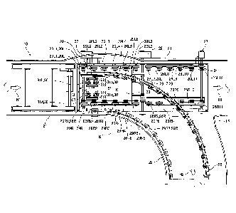
FIG. 1 is a plan view of a branch section of a conveyor
according to the present invention;
FIG. 2A is a plan view illustrating a tray conveyed to
the branch section of the conveyor according to the present
invention;
FIG. 2B is a plan view illustrating the tray conveyed
along a curved path of the conveyor according to the present
invention;
FIG. 3A is a cross-sectional view taken along line A-A
of FIG. 2A when the tray is conveyed along a linear path;
FIG. 3B is a cross-sectional view taken along line A-A
of FIG. 2A when the tray is conveyed along the curved path;
FIG. 4A is a side view illustrating the vicinity of an
orientation assist member when the tray at the branch
section is conveyed along the linear path by the conveyor
according to the present invention;
FIG. 4B is a side view illustrating the vicinity of the
orientation assist member when the tray at the branch
section is conveyed along the curved path by the conveyor
according to the present invention;
8
Date recue/Date Received 2021-01-20
FIG. 5A is a plan view immediately before a tray enters
a curved path, the tray being conveyed at a branch section
along the curved path by a conveyor of the related art;
FIG. 5B is a plan view when the tray enters the curved
path, the tray being conveyed at the branch section along
the curved path by the conveyor of the related art; and
FIG. 5C is a plan view immediately after the tray enters
the curved path, the tray being conveyed at the branch
section along the curved path by the conveyor of the related
art.
Description of the Embodiment
[0014]
A conveyor 10 according to an embodiment of the present
invention will be described below.
The conveyor 10 is provided in a sorting facility
(illustrated) for sorting hand baggage or freights in, for
example, an airport or a distribution center. As illustrated
in FIGS. 1, 2A, and 2B, the conveyor 10 conveys a tray 91
(an example of "conveyed object"), on which articles 90 such
as hand baggage or freights are placed, along a
transportation path 20.
[0015]
As illustrated in FIGS. 2A, and 2B, the tray 91 conveyed
by the conveyor 10 is a long plate on which the articles 90
can be placed and has a length L in the longitudinal
direction. The tray 91 is conveyed along the transportation
path 20 such that the longitudinal direction is placed along
a conveying direction (the longitudinal direction along the
conveying direction of the tray 91). On the tray 91, the
9
Date recue/Date Received 2021-01-20
articles 90 are respectively placed in a front-half region
in the longitudinal direction of the tray 91 (a front half
92 of the tray 91) and a rear-half region in the
longitudinal direction of the tray 91 (a rear half 93 of the
tray 91). A line passing through a center P of the tray 91
in the width direction serves as the boundary of the
regions. In FIGS. 2A and 2B, the articles 90 are placed in
the front half 92 of the tray 91 and the rear half 93 of the
tray 91 for convenience of explanation. The positions of the
articles 90 placed on the tray 91 are not limited to the
front half 92 of the tray 91 and the rear half 93 of the
tray 91.
[0016]
The transportation path 20 where the tray 91 is conveyed
includes a linear path 21, a curved path 22, and a branch
section 23 where the curved path 22 branches from one side
of the linear path 21 (in FIG. 1, from the right side in a
conveying direction H of the tray 91 on the linear path 21).
The linear path 21, the curved path 22, and the branch
section 23 are combined as necessary.
[0017]
As illustrated in FIG. 1, at the branch section 23, a
linear track 24 and a branch track 25 partially overlap each
other. The linear track 24 is provided for guiding the tray
91 guided from the linear path 21 on the upstream side of
conveyance, to the linear path 21 on the downstream side of
conveyance. The branch track 25 is provided for guiding the
tray 91 guided from the linear path 21 on the upstream side
of conveyance, to the curved path 22 branching to the
downstream side of conveyance. The linear track 24 and the
Date recue/Date Received 2021-01-20
branch track 25 have a top upstream position U on the linear
path 21, on the upstream side of conveyance from a starting
position S of the curved path 22 on the transportation path
20. The tracks extending downstream from the top upstream
position U are formed so as to partially overlap each other.
[0018]
The linear track 24 includes a plurality of right-side
rollers 26R and a plurality of left-side rollers 26L. The
right-side rollers 26R and the left-side rollers 26L are
provided at predetermined intervals in a frame, which is not
illustrated, and roll to move the tray 91 to the linear path
21. The right-side rollers 26R and the left-side rollers 26L
are driving rollers that are driven by a drive motor 27. The
right-side rollers 26R or the left-side rollers 26L may be
driving rollers and the other rollers may be driven rollers.
[0019]
As illustrated in FIGS. 1 to 4B, from among the right-
side rollers 26R and the left-side rollers 26L, right-side
rollers 26R1 to 26R6 and left-side rollers 26L1 to 26L6 that
overlap a plurality of right-side rollers 29R and a
plurality of left-side rollers 29L of the branch track 25
are configured so as to vertically move between a position
(FIG. 4A) for conveying the tray 91 to the linear path 21
and a position (FIG. 4B) for conveying the tray 91 to the
curved path 22. The right-side rollers 26R1 to 26R6 and the
left-side rollers 26L1 to 26L6 are vertically moved by the
driving of a drive motor 28 with the right-side roller 26R1
(left-side roller 26L1) serving as a pivot. When the tray 91
is conveyed to the linear path 21, the right-side rollers
26R1 to 26R6 and the left-side rollers 26L1 to 26L6 are kept
11
Date recue/Date Received 2021-01-20
at a predetermined position such that the roller height (a
height determined by the tangent of the highest point of the
right-side rollers 26R and the left-side rollers 26L) is
equal to the roller height of the right-side roller 29R1 and
the left-side roller 29L1 of the branch track 25 (a height
determined by the tangent of the highest point of the right-
side rollers 29R and the left-side rollers 29L) and is
higher than the roller height of the right-side rollers 29R2
to 29R6 and the left-side rollers 29L2 to 29L6.
Specifically, as illustrated in FIG. 3A, the highest point
of the right-side rollers 26R and the left-side rollers 26L
is kept at a position in contact with the bottom of the tray
91, whereas the highest point of the right-side rollers 29R2
to 29R6 and the left-side rollers 29L2 to 29L6 of the branch
track 25 is kept at a position lower than the highest point
of the right-side rollers 26R and the left-side rollers 26L.
The roller height of the right-side rollers 26R and the
left-side rollers 26L may be kept higher than the roller
height of the right-side roller 29R1 and the left-side
roller 29L1 of the branch track 25.
As illustrated in FIG. 3B, when the tray 91 is conveyed
to the curved path 22, the right-side rollers 26R and the
left-side rollers 26L move downward such that the roller
height is lower than that of the right-side rollers 29R and
the left-side rollers 29L of the branch track 25.
[0020]
As illustrated in FIG. 1, from among the right-side
rollers 26R and the left-side rollers 26L, right-side
rollers 26R7 to 26R11 and left-side rollers 26L7 to 26L12
that are positioned downstream of the right-side roller 26R6
12
Date recue/Date Received 2021-01-20
and the left-side roller 26L6 are always kept at a constant
roller height. The roller height is not changed in the
conveyance of the tray 91 to the linear path 21 and the
conveyance of the tray 91 to the curved path 22. The roller
height of the right-side rollers 26R7 to 26R11 and the left-
side rollers 26L7 to 26L12 may be changed when the rollers
are vertically moved to convey the tray 91 to the linear
path 21 or the curved path 22 with the right-side roller
26R11 (left-side roller 26L12) serving as a pivot. When the
tray 91 is conveyed to the linear path 21, the right-side
rollers 26R7 to 26R11 and the left-side rollers 26L7 to
26L12 are kept at a predetermined position such that the
roller height is higher than the roller height of the right-
side rollers 29R and the left-side rollers 29L, that is, the
right-side rollers from 29R7 and the left-side rollers from
29L7 of the branch track 25. When the tray 91 is conveyed to
the curved path 22, the right-side rollers 26R7 to 26R11 and
the left-side rollers 26L7 to 26L12 are moved downward such
that the roller height is lower than the roller height of
the right-side rollers 29R and the left-side rollers 29L,
that is, the right-side rollers from 29R7 and the left-side
rollers from 29L7 of the branch track 25.
[0021]
From among the right-side rollers 26R and the left-side
rollers 26L, the right-side roller 26R1 and the left-side
roller 26L1 at the top upstream position U of the linear
track 24 have the lowest roller height. The right-side
rollers 26R1 to 26R6 and the left-side rollers 26L1 to 26L6
are disposed at predetermined intervals toward the
downstream side of the linear track 24 so as to gradually
13
Date recue/Date Received 2021-01-20
increase in roller height from the right-side roller 26R1
and the left-side roller 26L1. The right-side rollers 26R
and the left-side rollers 26L downstream of the right-side
roller 26R6 and the left-side roller 26L6, that is, right-
side rollers 26R and the left-side rollers 26L from the
right-side roller 26R7 and the left-side roller 26L7 are
kept at a constant roller height and are disposed at
predetermined intervals toward the downstream side of the
linear track 24.
[0022]
The branch track 25 includes the right-side rollers 29R
and the left-side rollers 29L. The right-side rollers 29R
and the left-side rollers 29L are provided at predetermined
intervals in a frame, which is not illustrated, and roll to
move the tray 91 to the curved path 22. The left-side
rollers 29L are driving rollers that are driven by the drive
motor 27. The right-side rollers 29R are driven rollers that
are rolled in contact with the tray 91. The right-side
rollers 29R and the left-side rollers 29L may be driving
rollers.
[0023]
The right-side rollers 29R and the left-side rollers 29L
are disposed at predetermined intervals toward the
downstream side of the branch track 25 such that rollers of
the right-side rollers 29R and rollers of the left-side
rollers 29L are kept at a constant roller height
respectively.
[0024]
As illustrated in FIGS. 1, 3A, and 3B, at the top
upstream position U of the linear track 24 and the branch
14
Date recue/Date Received 2021-01-20
track 25, an orientation assist member 30 for assisting the
conveyance orientation of the tray 91 is provided. When the
tray 91 is conveyed from the linear path 21 to the curved
path 22, the orientation assist member 30 assists a change
of the conveyance orientation of the tray 91 from the
orientation of conveyance to the linear path 21 to the
orientation of conveyance to the curved path 22. The
orientation assist member 30 includes four wheels 31a, 31b,
31c, and 31d (an example of "rotating body") of Omni wheels
(registered trademark).
The wheels 31a, 31b, 31c, and 31d each include a body
part 32 and a barrel-shaped roller 33 (an example of
"rotating body") provided on the circumference of the body
part 32. The wheels 31a, 31b, 31c, and 31d can freely change
the rotation directions of the wheels according to a change
of the conveyance orientation of the tray 91 being conveyed
to the curved path 22, by combining the rotation of the body
part 32 (a movement in the conveying direction H1 of the
tray 91) and the rotation of the barrel-shaped roller 33 (a
movement in a direction horizontally perpendicular to the
conveying direction H1 of the tray 91). The body part 32
rotates in the same direction as the conveying direction H1
of the tray 91 on the linear path 21. The barrel-shaped
roller 33 rotates in the direction horizontally
perpendicular to the conveying direction H1 of the tray 91
on the linear path 21 (an example of "a direction at a
predetermined angle with respect to the conveying direction
of a conveyed object on the linear path"). The wheels 31a,
31b, 31c, and 31d are driven wheels that are rotated when
the barrel-shaped rollers 33 come into contact with the tray
Date recue/Date Received 2021-01-20
91. In other words, the wheels 31a, 31b, 31c, and 31d each
rotate the barrel-shaped roller 33 and the body part 32 when
the barrel-shaped roller 33 comes into contact with the tray
91.
[0025]
As illustrated in FIG. 1, the wheels 31a, 31b, 31c, and
31d are disposed in a predetermined range around a position
Si on the linear path 21, the position Si being separated at
a predetermined distance K on the upstream side of
conveyance from the starting position S of the curved path
22 on the transportation path 20. As illustrated in FIG. 2A,
the predetermined distance K is a distance corresponding to
a length from the center P of the tray 91 to a center P1 of
the rear half 93 of the tray 91. In other words, the
predetermined distance K is a distance corresponding to a
quarter of the length L (L/4) in the longitudinal direction
of the tray 91 (the length of the tray 91 in the conveying
direction). The rear half 93 of the tray 91 is the rear-half
region of an effective bottom that can be brought into
contact with the right-side rollers 26R, the left-side
rollers 26L, the right-side rollers 29R, the left-side
rollers 29L, and the wheels 31a, 31b, 31c, and 31d at the
bottom of the tray 91. Furthermore, the predetermined range
around the position Si on the linear path 21 is a range
where the rear half 93 of the tray 91 covers the linear path
21 when the center P1 of the rear half 93 of the tray 91
conveyed on the linear path 21 reaches the position Si on
the linear path 21.
[0026]
16
Date recue/Date Received 2021-01-20
As illustrated in FIGS. 1, 3A, and 3B, the four wheels
31a, 31b, 31c, and 31d are disposed at equal distances with
respect to the position Si on the linear path 21 and are
provided between a second right-side roller 26R2
constituting the linear track 24 and a second left-side
roller 29L2 constituting the branch track 25. Specifically,
the wheels 31a and 31b are disposed on the left side of the
conveying direction H1 of the tray 91 with respect to the
position Si so as to be opposed to the second left-side
roller 29L2. The wheels 31c and 31d are disposed on the
right side of the conveying direction H1 of the tray 91 with
respect to the position Si so as to be opposed to the second
right-side roller 26R2. The wheel 31a is linearly disposed
with the wheel 31b along the linear path 21. The wheel 31c
is linearly disposed with the wheel 31d along the linear
path 21. Moreover, the wheel 31a is opposed to the wheel 31c
in a direction horizontally perpendicular to the linear path
21. The wheel 31b is opposed to the wheel 31d in the
direction horizontally perpendicular to the linear path 21.
The four wheels 31a, 31b, 31c, and 31d are disposed in the
predetermined range around the position Si on the linear
path 21. Thus, when the center P1 of the rear half 93 of the
tray 91 conveyed on the linear path 21 reaches the position
Si on the linear path 21, the four wheels 31a, 31b, 31c, and
31d can be evenly brought into contact with the bottom of
the rear half 93 of the tray 91 and the bottom of the rear
half 93 of the tray 91 can be evenly supported by the four
wheels 31a, 31b, 31c, and 31d.
[0027]
17
Date recue/Date Received 2021-01-20
As illustrated in FIG. 3A, the wheels 31a, 31b, 31c, and
31d are disposed such that the roller height of the wheels
(a height determined by the tangent of the highest point of
the barrel-shaped roller 33 that is brought to the top
position of the body part 32 by the rotation of the body
part 32) is lower than the roller height of the second
right-side roller 26R2 and the second left-side roller 26L2
in the conveyance of the tray 91 to the linear path 21, and
the roller height of the wheels is higher by a height W than
the roller height of a second right-side roller 29R2 and the
second left-side roller 29L2 constituting the branch track
25. In other words, the wheels 31a, 31b, 31c, and 31d are
desirably disposed with a roller height between the roller
height of the second right-side roller 26R2 and the second
left-side roller 26L2 and the roller height of the second
right-side roller 29R2 and the second left-side roller 29L2
in the conveyance of the tray 91 to the linear path 21. By
the arrangement of the wheels 31a, 31b, 31c, and 31d, when
the tray 91 is conveyed to the linear path 21, the second
right-side roller 26R2 and the second left-side roller 26L2
that constitute the linear track 24 are brought into contact
with the bottom of the tray 91. When the tray 91 is conveyed
to the curved path 22, the second right-side roller 26R2 and
the second left-side roller 26L2 move downward to bring the
wheels 31a, 31b, 31c, and 31d into contact with the bottom
of the tray 91.
The roller height of the wheels 31a, 31b, 31c, and 31d
may be increased without interfering with the conveyance of
the tray 91 to the linear path 21 as long as the roller
18
Date recue/Date Received 2021-01-20
height is higher than that of the second right-side roller
29R2 and the second left-side roller 29L2.
[0028]
As illustrated in FIG. 3B, the wheels 31a, 31b, 31c, and
31d support the bottom of the rear half 93 of the tray 91
when the barrel-shaped roller 33 comes into contact with the
bottom of the tray 91 during the conveyance of the tray 91
from the linear path 21 to the curved path 22. Furthermore,
by the rotations of the body parts 32 and the barrel-shaped
rollers 33, the wheels 31a, 31b, 31c, and 31d move the rear
half 93 of the tray 91 to the left with respect to the
conveying direction H1 of the tray 91 on the linear path 21
(in a direction opposite to the curved path 22 (a conveying
direction H2 of the tray 91 on the curved path 22)) as
illustrated in FIG. 2B. In other words, the wheels 31a, 31b,
31c, and 31d assist a change of the orientation conveyance
for the rear half 93 of the tray 91 from the orientation of
conveyance to the linear path 21 to the orientation of
conveyance to the curved path 22.
[0029]
The movements of the tray 91 at the branch section 23 of
the conveyor 10 will be described below.
At the branch section 23 of the conveyor 10, the tray 91
is conveyed from the linear path 21 upstream of the branch
section 23 to the linear path 21 downstream of the branch
section 23. Alternatively, the tray 91 is conveyed from the
linear path 21 upstream of the branch section 23 to the
curved path 22 downstream of the branch section 23.
[0030]
19
Date recue/Date Received 2021-01-20
The tray 91 is conveyed to the linear path 21 downstream
of the branch section 23 by the right-side rollers 26R and
the left-side rollers 26L of the linear track 24. As
illustrated in FIGS. 3A and 4A, when the tray 91 is conveyed
to the linear path 21, the roller height of the right-side
rollers 26R2 to 26R6 and the left-side rollers 26L2 to 26L6
are kept higher than the roller height of the right-side
rollers 29R1 to 29R6 and the left-side rollers 29L1 to 29L6
of the branch track 25. The tray 91 is conveyed to the
linear path 21 by the rotations of the right-side rollers
26R and the left-side rollers 26L.
[0031]
The tray 91 is conveyed to the curved path 22 downstream
of the branch section 23 by the right-side rollers 29R and
the left-side rollers 29L of the branch track 25. As
illustrated in FIGS. 3B and 4B, when the tray 91 is conveyed
to the curved path 22, the right-side rollers 26R2 to 26R6
and the left-side rollers 26L2 to 26L6 of the linear track
24 move downward such that the roller height is lower than
the roller height of the right-side rollers 29R1 to 29R6 and
the left-side rollers 29L1 to 29L6 of the branch track 25
and the roller height of the wheels 31a, 31b, 31c, and 31d.
Specifically, in order to prevent the reception of a
resistance from the right-side rollers 26R1 to 26R6 and the
left-side rollers 26L1 to 26L6 of the linear track 24, the
right-side rollers 29R1 to 29R6 and the left-side rollers
29L1 to 29L6 of the branch track 25 and the wheels 31a, 31b,
31c, and 31d of the orientation assist member 30 are
disposed at a roller height that is higher than that of the
right-side rollers 26R1 to 26R6 and the left-side rollers
Date recue/Date Received 2021-01-20
26L1 to 26L6 of the linear track 24. The tray 91 is conveyed
to the curved path 22 by the driving of the rotations of the
left-side rollers 29L.
[0032]
As illustrated in FIGS. 2A and 2B, when a front end F (a
leading end of the front half 92 of the tray 91) of the tray
91 is conveyed to the starting position S of the curved path
22 on the transportation path 20 and the front half 92 of
the tray 91 is guided to the curved path 22 by the right-
side rollers 29R and the left-side rollers 29L of the branch
track 25, the conveyance orientation of the tray 91 is
changed from the orientation of conveyance to the linear
path 21 to the orientation of conveyance to the curved path
22 by a force for guiding the front half 92 of the tray 91
to the curved path 22 by the left-side rollers 29L of the
branch track 25. Specifically, the front half 92 of the tray
91 is being turned to the curved path 22, and the rear half
93 of the tray 91 is being slid to the left with respect to
the conveying direction H1 of the tray 91 on the linear path
21 (in a direction opposite to the curved path 22 (the
conveying direction H2 of the tray 91 on the curved path
22)).
[0033]
In this case, if a load is substantially uniformly
applied to the front half 92 and the rear half 93 of the
tray 91, the rear half 93 of the tray 91 slides when the
front half 92 of the tray 91 is being turned to the curved
path 22. In other words, when the front half 92 of the tray
91 changes from the orientation of conveyance to the linear
path 21 to the orientation of conveyance to the curved path
21
Date recue/Date Received 2021-01-20
22, the rear half 93 of the tray 91 is being changed from
the orientation of conveyance to the linear path 21 to the
orientation of conveyance to the curved path 22. This guides
the tray 91 to the curved path 22 without colliding the
front half 92 of the tray 91 with a corner guide 15.
If a load applied to the tray 91 is biased to the rear
half 93 of the tray 91 (rearward load), a resistance against
the sliding of the tray 91 increases. This disturbs the
balance between a force for turning the front half 92 of the
tray 91 to the curved path 22 and a force for sliding the
rear half 93 of the tray 91. Thus, the rear half 93 of the
tray 91 cannot slide when the front half 92 of the tray 91
is being turned to the curved path 22. Specifically, the
rear half 93 of the tray 91 cannot be changed from the
orientation of conveyance to the linear path 21 to the
orientation of conveyance to the curved path 22 when the
front half 92 of the tray 91 is changed from the orientation
of conveyance to the linear path 21 to the orientation of
conveyance to the curved path 22, so that the tray 91 cannot
fully turn to the curved path 22 and the front half 92 of
the tray 91 collides with the corner guide 15.
Thus, in the conveyor 10, the orientation assist member
30 is disposed in the predetermined range around the
position 51 on the linear path 21, thereby reducing a
resistance against the sliding of the tray 91, the
resistance being caused by a rearward load of the tray 91.
Specifically, when the front half 92 of the tray 91 is
turning to the curved path 22, the rear half 93 of the tray
91 comes into contact with the barrel-shaped rollers 33 of
the wheels 31a, 31b, 31c, and 31d of the orientation assist
22
Date recue/Date Received 2021-01-20
member 30. The rear half 93 of the tray 91 comes into
contact with the barrel-shaped rollers 33, so that the
barrel-shaped rollers 33 rotate and move the rear half 93 of
the tray 91 to the left with respect to the conveying
direction H1 of the tray 91. Thus, the sliding of the rear
half 93 of the tray 91 is assisted by the rotations of the
wheels 31a, 31b, 31c, and 31d, facilitating the sliding of
the rear half 93 of the tray 91 to the left with respect to
the conveying direction H1 of the tray 91. In other words, a
change of conveyance orientation is assisted for the rear
half 93 of the tray 91 by the orientation assist member 30,
facilitating a change of the conveyance orientation of the
rear half 93 of the tray 91 from the orientation of
conveyance to the linear path 21 to the orientation of
conveyance to the curved path 22. Hence, the conveyance
orientation of the rear half 93 of the tray 91 can be
changed according to a change of the conveyance orientation
of the front half 92 of the tray 91.
[0034]
As described above, according to the present embodiment,
when the tray 91 is conveyed from the linear path 21 to the
curved path 22, the orientation assist member 30 assists a
change of the conveyance orientation of the tray 91 (a
change of the conveyance orientation of the tray 91 from the
orientation of conveyance to the linear path 21 to the
orientation of conveyance to the curved path 22) on the
linear path 21 on the upstream side of conveyance from the
starting position S of the curved path 22 on the
transportation path 20. Thus, a resistance against the
sliding of the rear half 93 of the tray 91 is reduced, the
23
Date recue/Date Received 2021-01-20
resistance being caused by a rearward load of the tray 91,
and the balance is kept between a force for turning the
front half 92 of the tray 91 to the curved path 22 and a
force for moving the rear half 93 of the tray 91 in a
direction opposite to the curved path 22. Thus, when the
front half 92 of the tray 91 changes to the orientation of
conveyance to the curved path 22, the rear half 93 of the
tray 91 can be changed to the orientation of conveyance to
the curved path 22. This allows the tray 91 with a rearward
load to fully turn to the curved path 22 without colliding
with the corner guide 15 of the curved path 22.
[0035]
In the present embodiment, the orientation assist member
30 (wheels 31a, 31b, 31c, and 31d) includes, but not limited
to, Omni wheels (registered trademark). The orientation
assist member 30 may include, for example, Mecanum wheels
(registered trademark), free ball bearings, or casters as
long as the rear half 93 of the tray 91 is moved in a
direction opposite to the extended curved path 22 so as to
change the conveyance orientation of the rear half 93 of the
tray 91.
Alternatively, the orientation assist member 30 may
include a belt conveyor. When the tray 91 is conveyed to the
curved path 22, the belt conveyor may be pressed to the
bottom of the tray 91 so as to assist a change of the
conveyance orientation of the tray 91. In this case, the
belt conveyor has a belt section that rotates in a direction
at a predetermined angle with respect to the conveying
direction H1 of the tray 91 on the linear path 21.
24
Date recue/Date Received 2021-01-20
In the present embodiment, the wheels 31a, 31b, 31c, and
31d are, but not limited to, driven wheels that are rotated
when the barrel-shaped rollers 33 come into contact with the
tray 91. The wheels 31a, 31b, 31c, and 31d may include
driving wheels that are driven by a drive motor.
In the present embodiment, the orientation assist member
30 includes, but not limited to, four rotating bodies
(wheels 31a, 31b, 31c, and 31d). The number of rotating
bodies is not limited to four as long as the rear half 93 of
the tray 91 can be slid in a direction opposite to the
extended curved path 22 so as to change the conveyance
orientation of the rear half 93 of the tray 91. The
orientation assist member 30 may include one to three
rotating bodies or at least five rotating bodies.
In the present embodiment, the four rotating bodies
(wheels 31a, 31b, 31c, and 31d) of the orientation assist
member 30 are disposed, but not limited to, at equal
distances with respect to the position Si on the linear path
21. The four rotating bodies (wheels 31a, 31b, 31c, and 31d)
may not be disposed at equal distances as long as the
rotating bodies are located so as to be able to assist a
change of the conveyance orientation of the tray 91 when the
tray 91 is conveyed from the linear path 21 to the curved
path 22.
In the present embodiment, the articles 90 placed on the
tray 91 are conveyed by the conveyor 10, but not limited
thereto. The articles 90 may be directly conveyed by the
conveyor 10 without being placed on the tray 91.
[Reference Signs List]
Date recue/Date Received 2021-01-20
[0036]
conveyor
transportation path
21 linear path
22 curved path
orientation assist member
31a wheel(rotating body)
31b wheel(rotating body)
31c wheel(rotating body)
31d wheel(rotating body)
91 tray(conveyed object)
26
Date recue/Date Received 2021-01-20