Note: Descriptions are shown in the official language in which they were submitted.
I
CLAMPING STRAP FOR MOUNTING A COMPONENT
The invention relates to a device for holding a tubular component on a vehicle
chassis.
Such a device exemplarily allows to fix exhaust components to a chassis of a
vehicle. However,
the device will be subjected to significant mechanical loads during its
lifetime. This results from
the weight of these components, vibrations caused by combustion engine
operation and road
conditions. For example, a Diesel particle filter may be held by such a device
and have a weight
of as much as 20 kg. Consequently, suitable devices for holding an exhaust
component should
have a sufficient durability.
Common devices for holding tubular components, such as exhaust components,
comprise a
bracket that is to be attached to the vehicle, as well as a strap to be
wrapped around the
component. The strap is commonly attached to the bracket by welding. However,
in some
circumstances it may be a challenge to wrap the strap around the component
when the bracket
is al-ready in place. Also, a welded connection may require an increased
accuracy to avoid
potentially weakened regions, where a breakage may occur.
It is the object of the invention to propose a device for holding a tubular
component on a vehicle,
which allows to provide a reliable and vibration-resistant connection of the
tubular component
and the vehicle, while the welding of a strap to a bracket shall be avoided
and while the
assembly shall be as simple as possible.
A device for holding a tubular component on a vehicle is proposed, the device
comprising a
bracket, two strap parts and at least two trunnions, wherein both strap parts
on one end com-
prise a loop and on an opposed end a connection surface, wherein the bracket
comprises at
least one receiving opening for each trunnion to hold the respective trunnion
in the at least one
receiving opening, wherein each loop is dimensioned to allow one of the
trunnions to extend
through the loop when being placed in the respective at least one receiving
opening of the
bracket, wherein the connecting surfaces are shaped so as to be connectable to
each other so
Date Recue/Date Received 2022-08-31
CA 03106595 2021-01-15
WO 2020/057547
PCT/CN2019/106428
- 2 -
as to form a closed strap and wherein the bracket comprises a holding device
for attaching the
bracket to the vehicle.
The device is capable of reliably holding a tubular component on a vehicle,
while the used com-
.. ponents are simple, easy to manufacture, sturdy and reliable. The bracket
acts as an interface
between the vehicle and the two strap parts, which together hold the tubular
component. It is
not required to weld the strap parts to the bracket and the strap parts are
simply attached
through the use of the trunnions.
The bracket may preferably be shaped to provide a smooth radial inner contour
of the device,
which conforms the radial outer contour of the component to be held to avoid
uneven stresses.
When describing the shape and the advantages of the bracket, the face of the
bracket that
touches the tubular component will be referred to as the inner radial face.
Consequently, the
face opposed thereto in a radial direction will be referred to as the outer
radial face. In analogy
to this the bracket also comprises axial faces as well as circumferential
faces.
Instead of using a single, welded-on strap with two opposed and connectable
ends it is pro-
posed to use two separate strap parts, which can be attached to the bracket
through a form-fit
connection. For this purpose, both strap parts comprise a loop. The loop may
be provided
through folding or bending an end of the respective strap part about
substantially 1800, such
that an eye or a lug is created. The end may be folded onto an outer or inner
radial surface of
the strap part. The resulting two layers of the strap part may be joined
together through rivets or
spot-on welding, which can be accomplished by simply clamping the two layers
together and
introducing a welding current for a sufficient period of time. In this regard
it is stressed that the
operational load exerted onto the welding spots are much lower than what
occurs in a welding
connection between a bracket and strap in conventional devices.
Both strap parts comprise an end that is opposed to the loop and that
comprises a connection
surface. In the context of the invention, the connection surf acesare to be
understood as surfac-
es or surface sections, which can be connected to each other so as to combine
both strap parts
to form a closed strap. The strap parts are preferably adapted to the shape of
the tubular com-
ponent to be fixed. Hence, they may be placed around the component such that
the connection
surfaces face each other. Preferably, when the strap parts are in place, the
connection surfaces
are at a distance to each other. This allows to introduce a clamping force
through a tensioning
.. devices, such as a screw or similar, which pulls the connection surfaces to
each other.
CA 03106595 2021-01-15
WO 2020/057547
PCT/CN2019/106428
- 3 -
In a simple embodiment, the strap parts are flat, belt-like parts, which are
preferably made from
a metallic material. The loops may have a drop-like cross-section with a
broader end and a nar-
row end. In an assembled state, the trunnions may extend through the cross-
section of the
loops at a place near the broader end.
Preferably, the trunnions have a length that exceeds the width of the loop in
an axial direction of
the device, Le, in a direction substantially along a center axis or parallel
thereto. By exceeding
the width, both opposed ends of the trunnions are capable of protruding over
the loop. The ends
may engage the bracket in the respective receiving openings. Resultantly, the
associated strap
part cannot be removed from the bracket anymore, since the loop encloses the
respective trun-
nion. High tensile forces can then be transferred between the strap parts and
the bracket.
The trunnions may be realized as elongate parts, which may comprise engagement
features at
least at one end. For example, one end of the trunnions may comprise a stepped
diameter that
acts as a mechanical stop for preventing a trunnion to slip through a
receiving opening of the
bracket in one direction. For example, another end of the trunnions may
comprise a thread for
receiving a nut. As an alternative, a through-hole arranged perpendicularly to
the main exten-
sion direction of the trunnion may be used. Other alternate securing elements
are conceivable.
In particular, a securing element to provide a mechanical stop for preventing
the trunnion to slip
through a receiving opening in the other direction may be useful. It may also
be possible to de-
sign the trunnions in such a way that at least one of the ends may be deformed
after inserting it
into the respective loop and the bracket, so as to irreversibly providing
mechanical stops at both
ends.
Due to holding the strap parts in the bracket through trunnions it is easily
possible to swivel the
strap parts around the trunnions. Placing the strap parts around the component
is therefore very
easy. Also, by using trunnions that can be inserted into and secure in the
brackets the strap
parts may be placed on the component to be held and be connected to the
bracket afterwards
by simply inserting and securing the trunnions. However, the assembled device
is extremely
durable, allows high tensile forces and can be assembled flexibly.
The holding device of the bracket may be realized in a variety of ways. For
example, the holding
device may simply be a through-hole, through which a screw, a bolt or another
fastening device
may be placed, which is able to fix the bracket to a corresponding part on the
vehicle. However,
CA 03106595 2021-01-15
WO 2020/057547
PCT/CN2019/106428
- 4 -
also a threaded hole may be provided, which allows to screw a separate
fastening device into
the bracket. Still further, the bracket itself may be provided with an
elongate or a belt-like fasten-
ing device that protrudes from the bracket for attachment to the vehicle.
Altogether, the device according to the invention provides a simple solution
for holding a tubular
component on a vehicle without the need of welding metallic straps to a
bracket. Also, the as-
sembly procedure is easy, while a reliable operation substantially over the
lifetime of the vehicle
can be ensured.
In an advantageous embodiment, the bracket has a box-like shape, wherein two
opposed faces
in the circumferential direction of the device are open to lead the strap
parts through. The
bracket may exemplarily be created by a belt-like part, which is folded to
form a box-like shape.
In fact, the belt-like part may then constitute a somewhat angular loop. The
inner radial face of
the bracket will be placed on an outer surface of the tubular component. The
strap parts extend
from the trunnions along the circumferential direction to enclose the tubular
component. Hence,
the circumferential faces, i.e. the faces that are positioned and spaced apart
along the circumfe-
rential direction, are open. They may be open completely or partially, as long
as the strap parts
may reach outside the bracket.
The bracket may also comprise a radial outer face, into which the holding
device is integrated or
to which it is attached. When the bracket is placed on the component, the
radial outer face fac-
es away from the component. Hence, with the holding device being arranged
thereon, the
bracket will be placed between the vehicle part, to which the device will be
attached, and the
component. The radial outer face may preferably be designed to improve the
load transfer be-
tween the holding device and the component held by the strap parts.
As stated above, in an advantageous embodiment the holding device comprises a
hole in the
radial outer face for inserting a fastening device. The hole may be a through-
hole, while the fas-
tening device may comprise a mechanical end stop, to prevent the fastening
device from slip-
ping through the hole. Also, the hole may be a threaded hole and the fastening
device may
comprise a thread and may be inserted through screwing. In this case it may be
secured by a
nut or a similar component, which is screwed onto the thread of the fastening
device.
Advantageously, the bracket comprises two axial faces, which each comprise a
receiving open-
ing for each trunnion.The axial faces are arranged in a distance to each other
along the axial
CA 03106595 2021-01-15
WO 2020/057547
PCT/CN2019/106428
- 5 -
direction. With two receiving openings in the two axial faces for each
trunnion, the trunnions
may be aligned substantially parallel to the axial direction. Hence, the strap
parts that are
coupled with the trunnions extend along the circumferential direction. By
providing two receiving
openings for each trunnion, they may be inserted from one axial side into one
of the axial faces
to reach an interior space of the bracket, and from there they may be inserted
into a corres-
ponding receiving opening in the opposed axial face. With the loops of the
strap parts being
placed in the bracket, the trunnions extend through the loops and provide a
loose form-fit en-
gagement. The trunnions may afterwards be secured to the bracket by a
fastening device or by
conducting a fastening method to deform at least one end of the trunnions.
Still further, an inner radial face of the bracket may comprise the shape of a
segment of a lateral
cylinder surface. The inner radial surface may therefore flushly rest on the
tubular component to
be held by the device according to the invention.
As mentioned further above, each strap part may be based on a belt-like
workpiece, wherein
one end of the workpiece is folded to form the loop of the respective strap
part. The loop allows
to introduce high tensile forces into the strap parts and still allows a
certain movability for simpli-
fying the assembly.
In an advantageous embodiment, the trunnions comprise a fastening hole in at
least one end
section, wherein the fastening hole extends perpendicularly to a main
extension direction of the
trunnion and wherein the device further comprises a correspondingly
dimensioned securing
element for each fastening hole of each trunnion. For example, the securing
element may be a
split pin. The combination of the fastening hole and the split pin or another
securing element
acts as a fastening device. After inserting the trunnion into a respective
receiving opening, the
fastening hole should extend to a side that follows along the insertion
direction. By inserting
and/or arresting the securing element into the fastening hole, it provides the
function of a me-
chanical stop and prevents a movement in a direction opposite to the insertion
movement.
Preferably, the connection surfaces protrude radially from the strap parts and
comprise through-
holes for inserting a clamping device. The clamping device may be a simple
screw or screwing
device, which is insertable through both through-holes of the connection
surfaces and which
allows applying a tensioning force onto the connection surfaces. Resultantly,
the space en-
closed by the strap parts can be gradually reduced through the clamping device
and the clamp-
ing force that acts on the tubular component can be adjusted.
CA 03106595 2021-01-15
WO 2020/057547
PCT/CN2019/106428
- 6 -
Furthermore, it is indicated that the parts of the device according to the
invention may be made
from a metallic material. This may be reasonable for components that have an
elevated tem-
perature during operation of the vehicle, as well as for components having a
substantial weight.
However, the parts may also be made from a plastic material, which may
optionally be fiber
reinforced, to save weight, labor and costs.
Further features, details and advantages of the invention arise from the
wording of the claims as
well as from the following description of exemplary embodiments on the basis
of the drawings. It
is shown:
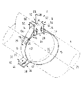
Fig. 1shows a three-dimensional view of the device according to the invention.
Fig. 2a and 2b show different two-dimensional view of the bracket.
Fig. 1 depicts a device 2 for holding a tubular component 4 on a vehicle (not
shown). In this re-
gard it is indicated that the term "tubular" does not necessarily relate to a
component, which is
completely tubular. Instead, the component to be held may simply comprise a
tubular or cylin-
drical section that is capable of being enclosed by the device 2 according to
the invention.
The device 2 comprises a bracket 6, a first strap part 8, a second strap part
10, a holding device
12 and two trunnions 14. Both strap parts 8 and 10 are based on a belt-like
workpiece, which is
preferably made from a metallic material. The first strap 8 comprises a first
loop 16, which is
created by folding or bending an end of the first strap about 180 , such that
an end section 18
rests flushly on an outer radial surface 20 of a first clamping section 22,
which is bent to con-
form the shape of the component 4. The end section 18 is rigidly connected to
the clamping
section 22 exemplarily in a number of fastening spots 24, which may be
conducted by introduc-
ing rivets or by spot-on welding.The loop 16 allows to connect the first strap
8 to the bracket 6
by a trunnion 14, such that high tensile forces can be introduced, while a
swiveling motion
around the trunnion 14 is still possible. The same principle applies to the
second strap part 10,
which has a second loop 28 with a similar end section 18 attached to a second
clamping section
30.
The first strap part 8 and the second strap part 10 are intended for clamping
the tubular compo-
nent 4. For this, the first strap part 8 comprises a first connection surface
32, which is connecta-
CA 03106595 2021-01-15
WO 2020/057547
PCT/CN2019/106428
- 7 -
ble to a second connection surface 34 arranged at the second strap part 10. In
this regard, the
connection surfaces 32 and 34 may each belong to a projecting web 36 and 38,
respectively
and face each other. The webs 36 and 38 each comprise a through-hole 40 and
42, respective-
ly. As an example, the second web 38 comprises an elongate through-hole 42 for
compensating
manufacturing tolerances of the device 2 or the component 4 for being able to
smoothly lead a
clamping device (not shown) through both through-holes 40 and 42.
For an optimum alignment of the webs 36 and 38, the first web 36 comprises an
outer edge 44
that is folded about 90 degrees towards the second web 38. When the second web
38 is
pressed against the first web 36 it cannot move in a radial direction further
than the edge 44
allows.
Hence, the device 2 may be wrapped around the tubular component 4 under
swiveling the strap
parts 8 and 10 radially outwards, placing the device 2 onto the component 4
and swiveling the
strap parts 8 and 10 back into place. Afterwards, a clamping device can be
inserted into the
through-holes 40 and 42 to exert a tensioning force onto the webs 36 and 38 to
tighten the de-
vice 2 on the component 4. In doing so, the connection surfaces 32 and 34
gradually decrease
their distance and the space enclosed by the strap parts 8 and 10 decreases
accordingly.
Exemplarily, the bracket 6 has a box shape, which is apparent from the
illustration in Fig. 1 as
well as from Figs. 2a and 2b. The bracket 6 comprises a radial inner face 46,
a radial outer face
48 opposed thereto, a first circumferential face 50, a second circumferential
face 52 opposed
thereto, a first axial face 54 and a second axial face 56 opposed thereto. As
apparent from Fig.
1 and Fig. 2a, the inner radial face 46 is rounded so as to conform with the
curved outer shell of
the tubular component 4. The outer radial face 48, at which the holding device
12 is present, is
exemplarily flat. For allowing the loops 16 and 28 to reach into an interior
space of the bracket 6,
the circumferential faces 50 and 52 are open.
Exemplarily, the axial faces 54 and 56 both comprise two receiving openings 58
arranged at a
distance to each other. They may preferably be placed in a symmetrical fashion
on the axial
faces 54 and 56. The receiving openings 58 of both axial faces 54 and 56 are
positioned to be
directly opposed to the receiving openings 58 of the respective other axial
face 56 or 54. Hence,
there are two pairs of directly opposed receiving openings 58 for receiving a
trunnion 14 in each
case.
CA 03106595 2021-01-15
WO 2020/057547
PCT/CN2019/106428
- 8 -
Both trunnions exemplarily comprise a stepped portion 60 having a diameter
larger than the
receiving opening 58. Thus, the trunnions 14 can be inserted into one of the
receiving openings
58 on one of the axial faces 50 or 52, pushed through one of the loops 16 or
28, when placed in
the bracket 6, and afterwards pushed through the opposed receiving opening 58
of the other
axial face 52 or 50. The stepped portions 60 stop the trunnions 14 when
completely pushed
through and placed in the desired locations.
At an end opposite to the stepped portion 60, a fastening hole 62 exemplarily
extends through
each trunnion 14. The fastening hole 62 is substantially aligned vertically to
a main extension
direction of the trunnion 14. This allows to put a split pin 64 into the
fastening hole 62. After
bending at least a section of the split pin 64 the trunnion 14 is secured in
place. However, other
securing elements are possible.
In the shown example, the outer radial surface 48 comprises a hole 66, through
which a fasten-
ing device 68 extends. It may be realized as an elongate part that is
connectable to the vehicle.
However, the fastening device 68 may also be material-bonded to the bracket 6
or secured
through a nut at an inner side of the bracket 6 between the loops 16 and 28.
Other variants are
further conceivable.
The invention is not limited to one of the above-described embodiments but may
be modified in
a variety of ways.
All features and advantages of the claims that emanate from the description
and the drawings,
including design details, spatial arrangements and method steps may be
essential to the inven-
tion both by themselves and in various combinations.
CA 03106595 2021-01-15
WO 2020/057547
PCT/CN2019/106428
- 9 -
List of reference numerals
2 device
4 tubular component
6 bracket
8 first strap part
second strap part
12 holding device
14 trunnion
16 first loop
10 18 end section
outer radial surface
22 first clamping section
24 fastening spot
26 longitudinal axis
15 28 second loop
second clamping section
32 first connection surface
34 second connection surface
36 first web
20 38 second web
through-hole
42 elongate through-hole
44 outer edge
46 radial inner face
25 48 radial outer face
first circumferential face
52 second circumferential face
54 axial face
56 axial face
30 58 receiving opening
stepped portion
62 fastening hole
64 split pin
66 hole (in the outer radial surface)
35 68 fastening device